Table of contents
Introduction
•This instruction manual explains installation, operation,
troubleshooting, maintenance and inspection, and discarding
procedures for the products below:
•Vacuum constant-temperature dryer
•Vacuum Dry Oven;
•VOS-210C/VOS-310C
Items contained in your packing
Be sure to confirm the type and quantity of parts before setting.
1. For safe operation 1
2. Product Summary
2-1 Intended use 2
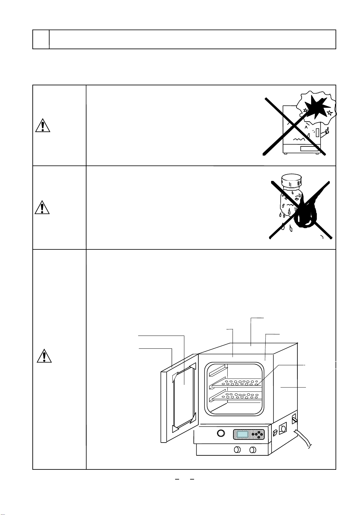
2-3 Names of parts 3
3. Names and Function of Operating Part
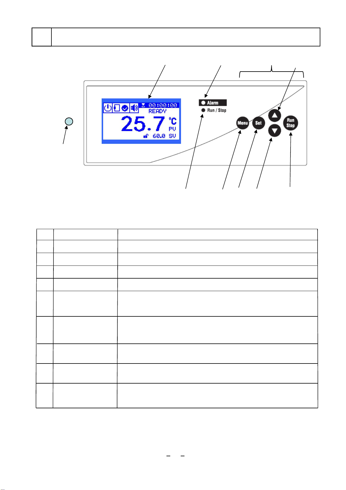
3-1 Control panel 4
3-5 Safety and alarm functions 9
4.Installation
4-3 Utility connections 13
5. Operation
5-1 Preparation for operation 14
5-1-1 Set shelf plates and connect to the vacuum
pump 146. Causes of Trouble and Countermeasures 39
7. Maintenance and Inspection
7-1 Leak breaker movement test 41
7-2 Cleaning and care of the product 41
8. Disposal of Product 42
9. Post-sale Service 43
4-2 Installation condition 12
2-2 Specification 2
4-1 Installation environment 12
7-3 Consumable Parts 42
Product
Description of Package
1 Main body
2 Shelf plate
3Instruction Manual
4Warranty
VOS-
310C
1
2
1
10.List of Consumable and Replacing Components/Parts
44
210C
1
2
1
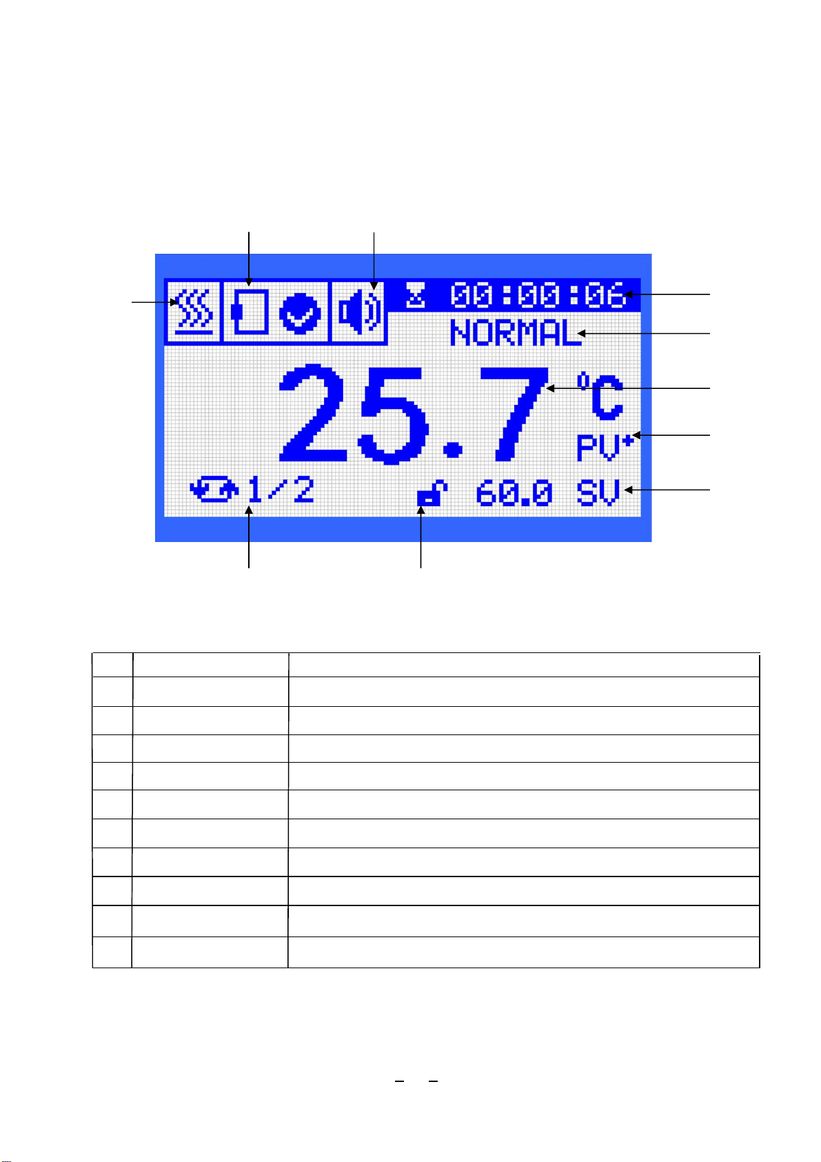
3-2 Display part 5
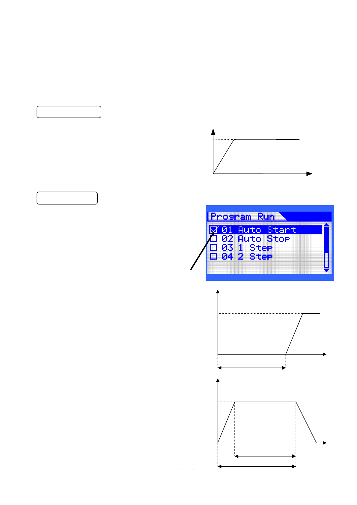
3-3 Constant-value operation and program run 6
3-4 Setting 8
5-5 Vacuum operation method 37
11
5-1-2 Setting sample and container in the chamber
14
5-1-3 Connect power plug 14
5-2 Operating method 15
5-2-1 Set overheat protector 15
5-2-2 Setting, running and stopping constant-value
operation 16
5-2-3 Setting, running and stopping program run 18
5-3-1 How to display alarm screen on the
temperature controller 25
5-4-6 Blackout recovery function 32
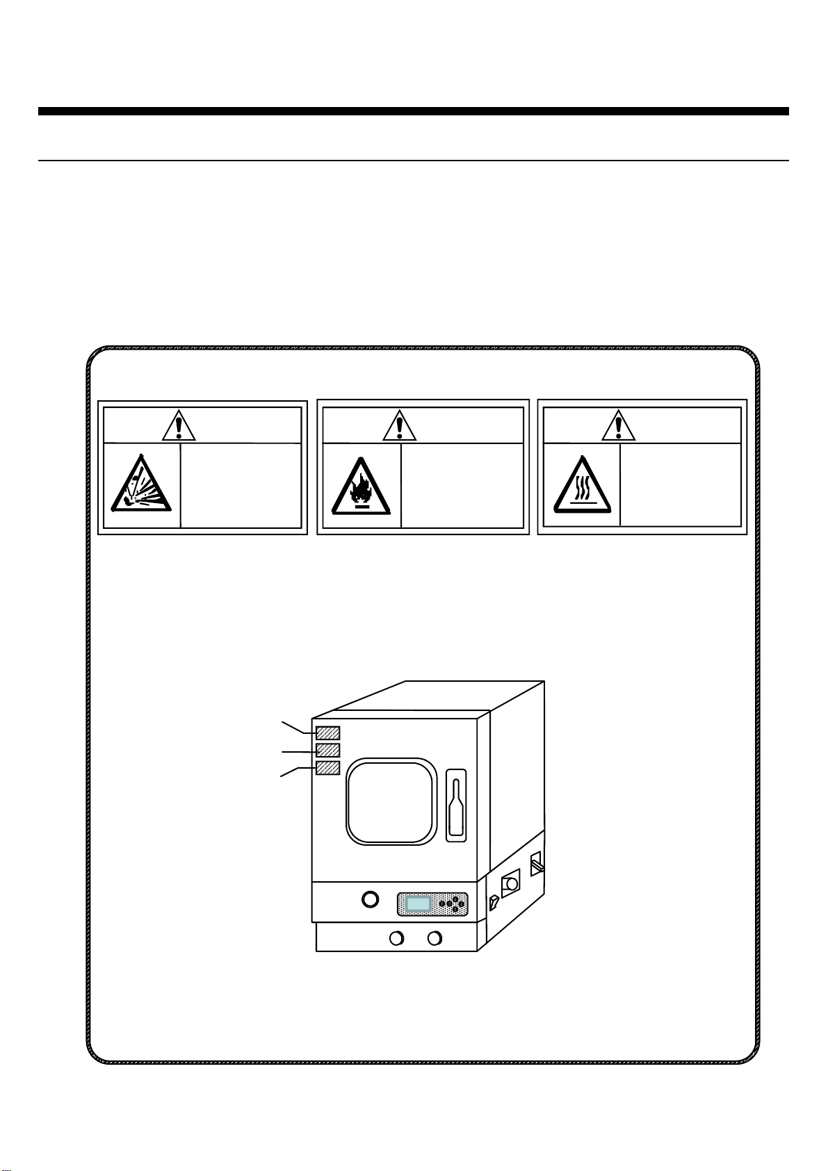
Always read this manual before use to ensure
familiarization of the product.
5-3 Alarm function of temperature controller 25
5-3-3 How to set Temp. Alarm 1 Upper/Lower
Limiter 26
5-3-4 How to set Temp. Alarm 2 Temperature
Setting Upper/Lower Alarm 27
5-4 Setting mode operating method 28
5-4-1 How to display setting mode28
5-4-2 PID channel 29
5-4-3 Custom PID 29
5-4-4 How to use Auto-Tuning 30
5-4-5 Measured temperature correction function
31
5-4-7 Optional features 33
5-4-8 Reset setting items 34
5-4-9 Lock operation keys 35
5-4-10 Adjust the display screen contrast 36
5-3-2 Temperature control alarm function 26
5-6 Gas replacing operation method 38
Thank you for purchasing our
product.