GE JK3000DF3WW User manual

Installation Instructions
27" & 30" Electric Built-in Wall Ovens
Questions? Call 1,800,GE,CARES (1,800,432,2737) or visit www,GEAppliances,com
In Canada, call 1,800,561,3344 or visit www,GEAppliances,ca
BEFORE YOU BEGIN
Read these instructions completely and
carefully,
" IM PORTANT -- Savetheseinstructions
for local inspector's use,
" IMPORTANT -- Observe all governing
(:odes and ordinances,
• Note to Installer - Be sure to leave these
instructions with Consumer,
• Note to Consumer - Keep these instructions
for future reference.
• Skill level - Installation of this appliance
requires a qualified installer or electrician.
• Proper installation is the responsibility
of the installer.
. Product failure due to improper installation
is not covered under Warranty.
. Product is for indoor use only.
ATTENTION INSTALLER: Aii electric wall ovens must be hard-wired (direcbwired)into an
approved junction box. A plug and receptacle is NOT permitted on these products.
FOR YOUR SAFETY:
AWARNING: Before begirrnirrg the ,rrstallation, switch power off at the service panel and
lock the service disconnecting means to prevent power from being switched on accidentally. When the
service disconnecting means cannot be locked, securely fasten a prominent warning device, such as a tag,
to the service panel.
Be sure the oven is securely irrstalled in a cabinet that is firmly attached to the house structure.
Weight orr the oven door could cause the oven to tip arrd result in injury. Never allow anyone to climb, sit,
stand or hang orr the oven door.
Make sure the wall coverings, counters and cabinets around the oven can withstand the Preat
(up to 200°F [93.3°C]) generated by the oven.
MATERIALS YOU MAY NEED
Junction Box
Wire Nuts
Strain Relief Clamp for 1/2" Conduit
TOOLS YOU MAY NEED
1/8" Drill Bit arrd Electric or Hand Drill
T20 Screwdriver
Phillips Screwdriver
Wire Strippers
DESIGN INFORMATION
SINGLE OVEN INSTALLATIONS
The single oven may be installed in a cabinet alorre or above a warming drawer. The single oven may also
be irrstalled below a countertop or below specified cooktops. See the label on top of the oven for approved
models.
DOUBLE OVEN INSTALLATIONS
A double oven may be irrstalled in a cabinet alone or above a warmirrg drawer. See the label on top of the
oven for approved models.
IMPORTANT: Always refer to individual installation irrstructions packed with each product for specific
requirements.
[_] PREPARE THE OPENING
NOTE: If the cabinet does not have a solid bottom, two
braces or runners must be installed to support the weight
of the oven. For single ovens, the runners and braces
must support 200 Ibs (91 kg). For double ovens, the
runners and braces must support 375 Ibs. (170 kg).
NOTE: If marks, blemishes or the cutout opening are
visible above the installed oven, it may be necessary to
add wood shims under the runners and front trim until
the marks or opening are covered.
NOTE: If the cabinet does not have a front frame and
the sides are less than 3/4"(1.9 cm) thick, shim both sides
equally to establish the cutout width.
2" x 4"{5 cm x 10 cm)
or Equivalent Runners Level
with Bottom of Cutout
and Flush with Sides of Cutout
Suitable
Bracing
to Support.
REMOVE PACKAGING MATERIALS
Failure to remove packaging materials could result in damage to the appliance. Remove all packing
parts from oven, racks and heating elements. Remove protective film and labels on the outer door
and control panel. Also, remove plastic on trims and panel, all tape around the oven and any shipping
screws securing the oven to the base pad. Open oven door and remove literature pack and oven
racks. Remove the bottom trim from the top of the oven. It will be installed at the end of the installation
process. The trim is wrapped separately and taped to the top of the unit. Remove pedestal rails from
seperate box and set aside (30" Double Wall Ovens Only).

[Tr_ CUTOUT FOR SINGLE OVENS IN WALL CABINET
NOTE: If the cabinet does not have a front flame and the sides are less than ¾" (1.9 cm) thick, shim
both sides equally to establish the cutout width.
These ovens
are not
approved for
stackable
installations.
Opening
Between Inside
Walls Must be
at Least 28-1/2'r
(72,4 cm) Wide
H
Side by Side Installations
Install two ovens in separate cutouts,
Center Line Center Line
305" (77.5cm)
! 30" models !
_27'r(68,58 cm) I
I 27"modes !
11 ! i
observe all
dimensions and
requirements
---_1 I<'-- 2"/5_cm)M_n
Junction
Box
Location
(junction
be located
in a d acent
cabinet)
22" (55.9
cm) Min to U ""_
Bottom of
Junction
Box
Cutout Depth
(59,7 cm) Min
Note: Allow
1/4" (064 cm)
clearances
horn side
edges of oven
door
_________B________
t
F
G
............................. .......
t
C
v
IA
Recommended
Cutout Location
from Floor
32 1/2" (82,6cm)
12
Dimension Dimension Description 27" Single Oven 30" Single Oven
A Cabinet Width 27" (68.6 cm) 30" (76.2 cm)
B Cutout Width 25" (63.5 cm) min. 281/z'' (72.4 cm) min.
25X" (64.1 cm) max. 28%" (72.7 cm) max.
C Cutout Height 27%" (70.2 cm) min. 271/4" (69.2 cm) min.
28W' (71.4 cm) max. 27_6" (69.4 cm) max.
D Overlap of Oven Over 1" (2.5 cm) 1X6" (1.75 cm)
Side Edges of Cutout
E Clearance to 23" (50.8 cm) min. 23" (53.3 cm) min.
Adjacent Corners,
Drawers, Walls, etc.,
When Door Is Open
F Overlap of Oven 1" (2.5 cm) min. 1" (2.5 cm) min.
Top of Cutout (11A" (3.2 cm) for PT9050)
G Overlap of Oven 1" (2.5 cm) min. 11/4"(3.2 cm)
Bottom of Cutout
H Junction Box Location 8¾" (22.2 cm) max. 91/z'' (24.1 cm) max.
right side only right side only
[TFB] CUTOUT FORSINGLE OVENS- UNDER COUNTER
NOTE: These ovens are only approved to be installed under the specific models as labeled on the unit.
Gas or Electric Cooktops May Re Installed Over This Oven.
See Cooktop Installation instructions for Cutout Size. 245V/208V
See Label on Top of Oven for Approved Models. Junction Box
Location (junction
box may be
in adjacent cabinet)
25" (63.5 cm)
Gas and Electrical Connections
for Gas Cooktop Must be Located
in an Adjacent Accessible
Location to the Right
MUST SUPPORT 200 Ibs. (90 kg) FOR SINGLE OVENS
MUST SUPPORT 375 Ibs. (170 kg) FOR DOUBLE OVENS
Side-by-Side Installations
Install two ovens in separate cutouts.
Center Line Center Line
I 305" (77,5 cm} 30'r models
"(68,58cm) 27"models
Ii
!
Cutout - observe _ Cutout - observe
all dimensions and l all dimensions and
requirements, requirements.
NOTE: One cooktop may be (:entered over either oven in
the side-by-side installation.
22" (55.9 crn) Min. 36" (91.4 cm)
Above Support
Platform Countertop
Height
Dimension Dimension Description 27" Single Oven 30" Single Oven
A Cabinet Width 25" (63.5 cm) min. 28Y/' (72.4 cm) min.
251A'' (64.1 cm) max. 28%" (72.7 cm) max.
B Cutout Height 27%" (70.2 cm) min. 271/4" (69.2 cm) min.
28_ '' (71.4 cm) max. 27:'A6" (69.4 cm) max.
C Unit Overlap Top 1" (2.5 cm) 1" (2.5 cm)
(11/4"(3.2 cm) for PTg050)
D _ Unit Overlap Bottom 1" (2.5 cm) 11/4"(3.2 cm)
E Unit Overlap Side Edges 1" (2.5 cm) 11A6"(1.75 cm)
F Junction Box Location 8¾" (22.2 cm) max. 91/z'' (24.1 cm) max.
right side only right side only
Continue to Section 4.

[TF_ CUTOUT FOR DOUBLE OVENS (2 THERMAL OVENS)
NOTE: If the cabinet does not have a front frame and the sides are less than 3/4" l1.9 cm)
both sides equal_h.i
Junction
Box
Location
(junction
Jbox may
be located
in adjacent
cabinet)
J
....[;y_ ¢
. -"" _ Cutout Depth
---_--_.. j_" 23-1/2"
(59,7cm}Min,
D _
t
F
G
t
hick, shim
k--
Dim. Description 27" Double Oven 30" Double Oven with 30" Double Oven
Pedestal without Pedestal
A Cabinet Width 27" (68.6 cm) 3(Y (76.2 cm) 3(Y (76.2 cm)
B Cutout Width 25" (63.5 cm) rain. 281½" (72.4 cm) rain. 281//' (72.4 cm) rain.
25W' (64.1 cm) max. 28_," (72.7 cm) max. 28%" (72.7 cm) max.
C Cutout Height 49_Ad'(1262 cm) min. 511SAd' (131.6 cm) rain. 50 V4" (127.64cm)
5()W' (127.3 cm) max. 511_6" (131.9 cm) max.
D Overlap of Oven 1" (2.5 cm) 11A6"(1.75 cm) 11A6"(1.75 cm)
Over Side Edges
of Cutout
E Clearance to 23" (50.8 cm) rain. 23" (53.3 cm) rain. 23" (53.3 cm) rain.
Adjacent Corners,
Drawers, Walls, etc.,
When Door Is Open
F Overlap of Oven 1" (2.5 cm) rain. 1" (2.5 cm) rain. 1" (2.5 cm) rain.
Top of Cutout (1W' (3.2 cm) for P19550) (I_A" (3.2 cm) for P19550)
G Overlap of Oven 1" (2.5 cm) rain. 1W' (3.2 cm) 11A" (3.2 cm)
Bottom of Cutout
H Junction Box 8¾" (22.2 cm) max. 91/Z' (24.1 cm) max. 91/Z' (24.1 cm) max.
Location right side only right side only right side only
J Height to Bottom 44" (111.8 cm) 47" (119.4 cm) 47" (119.4 cm)
of Junction Box
K Recommended 13W' (33.7 cm) 12" (30.5 cm) 12" (30.5 cm)
Cutout Location
from Floor
Continue to Section 3.
F_ CUTOUT FOR INSTALLATION OVER A WARMING DRAWER
NOTE: Install the oven only with specific models listed on the label located on top of the oven.
NOTE: Additional clearances between cutouts may be required. Check to be sure the oven supports
above the Warming Drawer location do not obstruct the required interior depth and height.
When installing a Warming Drawer below a single or double oven, a separate 120V, 60 HZ, properly
grounded receptacle must be installed. Refer to installation instructions packed with
the Warming Drawer for specific installation requirements.
Anti-Tip Block Against
Rear Wall Per Warming
Drawer Requirement
Per Warming
Drawer
Requirement
Continue to Section 3 for DWO with Pedestal. Otherwise, continue to Section 4.
J31-10958-1J GE

[_] PEDESTAL RAIL INSTALLATION (30" DOUBLE OVENS ONLY)
A. Place one pedestal rail on each cabinet runner or centered on opposite side of solid cabinet bottom
flush with side of cabinet opening. Locate each rail so that front of rail is behind front cabinet
opening.
B. Drill pilot holes and attach rails to runner or bottom of cabinet with provided hardware.
j--

_1 DOOR REMOVAL (RECOMMENDED)
NOTE: Door removal is not a requirement for installation of the product but is an added convenience.
To remove the door:
A. Open the oven door as far as it will go.
B. Remove hinge bracket from front frame and set aside. The hinge bracket must
be replaced for proper door functionality when door is reinstalled.
C. Push both hinge locks down toward the door frame to the unlocked position.
This may require a flat-blade screwdriver. DO NOT LIFT THE DOOR BY THE
HANDLE!
D. Place hands on both sides of the door and (:lose the oven door to the removal
position (approximately 1"-2" [2.5 cm-5.1 cm] from the closed position).
E. Lift the door up and out until the hinge arms (:lear the slots.
NOTE: The oven door is very heavy. Be sure
you have a firm grip before lifting the oven door off the hinges. Use caution
once the door is removed. Do not lay the door on its handle.
This could cause dents or scratches.
/ I_ Hinge Unlocked
Hinge Slot
Hinge Arm
Position
Hinge Clears Slot
Hinge Bracket
ELECTRICAL REQUIREMENTS
WARNING:Thisapp,iancem, stbeproper,ygrounded.
WARNING:To preverlt fire or shock, do rlot use arl extensk)n cord with this app,iarlce.
a,WARNING:To prevent shock, remove house fuse or operr circuit breaker before
beginning irrstallation.
a,WARNING:Improper corrrrectiorl of alurnirlum house wirirlg to copper leads carl result
in an electrical hazard or fire. Use only corrnectors designed forjoining copper to aluminum arrd follow the
manufacturer's recommended procedure closely.
We recommend you have the electrical wiring arrd hookup of your appliance corrnected by a qualified
electrician. After irrstallation, have the electrician show you how to disconnect power from the appliance.
You must use a single-phase, 120/208 VAC or 120/240 VAC, 60 Hertz electrical system. If you corrnect to
aluminum wiring, properly installed corrnectors approved for use with aluminum wiring must be used.
Effective January 1, 1996, the National Electrical Code requires that new construction (not existing) utilize
a four-conductor connection to an electric oven. When installing an electric oven in new construction,
a mobile home, recreational vehicle or an area where local codes prohibit grounding through the
neutral conductor, refer to the section on four-conductor branch circuit connections.
Check with your local utilities for electrical (:odes which apply in your area. Failure to wire your oven
according to governing codes could result in a hazardous condition. If there are no local (:odes, your
oven must be wired and fused to meet the National Electrical Code, NFPA No. 70 - latest edition,
available from the National Fire Protection Association.
F_ ELECTRICAL REQUIREMENTS (CONT.)
This appliance must be supplied with the proper voltage arrd frequency and corrnected to an individual,
properly grounded branch circuit, protected by a circuit breaker or fuse. See the rating plate located on the
oven frame to determine the rating of the product.
Rating P|ate
Location ....................................
Rating plate is located on the oven side trim.
Use the chart below to determine the minimum recommended dedicated circuit protection:
Recommended
KW Rating KW Rating Circuit Size
240V 208V (Dedicated)
<4.8 KW <4.t KW 20 Amp
4.9 KW-7.2 KW 4.2 KW-6.2 KW 30 Amp
7.3 KW-9.6 KW 6.3 KW-8.3 KW 40 Amp
9.7 KW-12.0 KW 8.4 KW-IO.4 KW 50 Amp
DO NOT shorten the flexible corrduit. The conduit strain relief clamp must be securely attached to the
junction box and the flexible corrduit must be securely attached to the clamp. If the flexible conduit will not
fit within the clamp, do not irrstall the oven until a clamp of the proper size is obtained.
The 3 power leads supplied with this appliance are suitable for connection to heavier gauge household
wiring. The irrsulation of these 3 leads is rated for temperatures much higher than the temperature rating of
the household wiring. The current-carrying capacity of the corrductor is governed by the wire gauge and the
temperature rating of the irrsulation around the wire.

F_ MAKE ELECTRICAL CONNECTIONS
A WARNING: witchpoweroffatthese vicepane,and,ocktheserv,codisconnoct,ng
means to prevent power from being switched on accidentally. When the service disconnecting means
cannot be locked, securely fasten a prominent warning device, such as a tag,
to the service panel.
Place oven on table or platform even with the cutout opening. For a single oven, the platform must support
200 Ibs. (91 kg); and for a double oven, the platform must support 375 Ibs. (170 kg). Connect the flexible
conduit to the electricaljunction box as shown belowL Position the conduit in such a manner that it will lie
behind the unit in a natural loop when the oven is installed. You will need to purchase an appropriate strain
relief clamp to complete the connection of the conduit to the junction box.
Junction Box
Conduit
Place Oven on a
Support to Assist in
Connecting Conduit
Strain Relief Clamp
(not included) Must Be
Used at ,Junction Box
_Ovens come equipped with a 40" long conduit. If a longer conduit is desired, there may be one available for
your model. To check availability or order parts, call 1.800.GE.CARES.
F_ THREE-CONDUCTOR BRANCH CIRCUIT CONNECTION
NOTE: If residence leads are aluminum conductors, see WARNING
in Section 5, Electrical Requirements.
When connecting to a three-conductor branch circuit, if local codes
permit:
A. Connect the bare oven ground conductor with the crimped
neutral (white) lead to the branch circuit neutral (white or gray in
color), using a wire nut.
B. Connect the oven red lead to the branch circuit red lead
and the oven black lead to the branch circuit black lead
in accordance with local (:odes, using wire nuts.
C. Install junction box (:over.
und
Neutral
es
unction Box
Cover
FOUR-CONDUCTOR BRANCH CIRCUIT CONNECTION
NOTE: If residence leads are aluminum conductors, see WARNING in Section 5, Electrical Requirements.
A. Cut the neutral (white) lead from the crimp. Re-strip the neutral (white) lead to expose
the proper length of conductor.
B. Attach the appliance grounding lead (green or bare copper)
in accordance with local (:odes. If the residence grounding
conductor is aluminum, see WARNING in Section 5.
C. Connect the oven neutral (white) lead to the branch circuit
neutral (white or gray) in accordance with local (:odes, using
a wire nut.
D. Connect the oven red lead to the branch circuit red lead
and the oven black lead to the branch circuit black lead
in accordance with local (:odes, using wire nuts.
NOTE: If the residence red, black or white leads are aluminum
conductors, see WARNING in Section 5.
E. Install junction box (:over.
Gro nd
unction Box
Cover
_-I SLIDE OVEN INTO OPENING
• Lift oven into cabinet cutout using the
oven opening as a grip. Carefully push
against oven front frame. Do not push
against outside edges.

F0-] MOUNT THE OVEN
AWARN ING:Mountings, rews
must be used. Failure to do so could result in
the oven falling out of the cabinet, causing
serious injury.
NOTE: During oven mounting step, ensure that no
damage is done to oven gasket which lines the
edge of oven cavity.
NOTE: Before drilling the pilot holes, make sure
the oven is pushed as far back into the opening
as it will go and is centered.
NOTE: If the cabinet is particle board, you must
use #8 x 3/4" particle board screws. These may be
purchased at any hardware store.
A. Drill through the mounting holes (top and
bottom) of the side trim for the #8 mounting
screws provided.
B. Secure the oven cabinet with the screws
provided.
Mounting
Hole
Locations
(hole locations
may vary)
The Screws
Must Be a
Minimum of
1/4" (6 mm)
From the
Front of
the Cutout.
BOTTOM TRIM INSTALLATION
*With oven installed, attach the bottom trim through its mounting holes in front vertical brace using
two trim screws provided. Bottom trim lip must be placed under flange of bottom air duct.
SWO's and DWO installations without pedestal
DWO's with pedestals
IMPORTANT: If this unit is ever removed from the cabinet or the oven is ever pulled out for service, Ithe bottom trim must be removed first or damage to the trim will occur. 1

OVEN RACK GUIDE INSTALLATION (IF APPLICABLE)
A. Locate included oven rack guide mouting hardware.
B. Place oven rack guides on cavity wall studs with L bracket towards back of cavity as shown.
C. Install guides using the 8 provided mounting nuts.
Oven rack
guide shown
in place.
REPLACING THE OVEN DOOR
NOTE: The oven door is heavy. You may need help lifting the door high enough
to slide it into the hinge slots. Do not lift the door by the handle.
A. Lift the oven door by grasping each side.
B. With the door at the same angle as the removal position (approximately
1"-2" [2.5 cm-5.1 cm] from the closed position), seat the notch of the hinge
arm into the bottom edge of the hinge slot. The notch of the hinge arm must
be fully seated into the bottom of the slot.
C. Fully open the door. If the door will not fully open, the indentation is not
seated correctly in the bottom edge of the slot.
D. Push the hinge locks up against the front frame of the oven cavity,
to the locked position.
E. Replace hinge bracket. The hinge bracket must be replaced for proper door
functionality.
IF, Close the oven door,
Hinge in
Locked
Position
J
Notch of Hinge
Securely Fitted
Into Bottom of
Hinge Slot
Hinge Bracket
Bottom i Hinge
Edgeof iI III I J
Slot 4__'
Hinge Notch
FINAL INSTALLATION CHECKLIST
•Check to make sure the circuit breaker is closed (RESET) or the circuit fuses are replaced.
•Be sure power is in service to the building.
•Check that all packing material and tape have been removed. Failure to remove these materials
could result in damage to the appliance once the appliance has been turned on and surfaces have
heated.
•Remove all items from inside the oven.
•Check to be sure that the mounting screws are installed and flush with the side trim
(see Section 10).
•Check that the bottom trim is installed properly (see Section 11).
•Ensure that air duct opening at bottom of unit is free of obstructions.
•Check that oven rack guides (if applicable) are installed correctly and oven racks function smoothly.
OPERATION CHECKLIST
•Turn on the power to the oven (refer to your Owner's Manual). Verify that the bake and broil units and
all cooking functions operate properly.
•See your Owner's Manual for the troubleshooting list.
•Be sure all of the oven controls are OFF before leaving the oven.

Instrucciones de instalacion
Homosdeparedelectricosempotradosde27"y30"
_,Preguntas? Llame al 1,800,GE,CARES (1,800,432,2737) o visite GEAppliances,com
En Canad& Ilame al 1,800,561,3344 o visite www,GEAppliances,ca,
ANTES DE COMENZAR
Lea estas instrueciones por eompleto y (:on
detenimiento.
" IMPORTANTE- Guardeestash<rucciones
para el uso de inspectores locales.
" IMPORTANT - Cumplacon_odoslosoodigosy
ordena nzas vigentes,
• Nota al instalador- Asegurese de dejar estas
instrucciones con el Consumidor,
•Nota al consumidor - Conserve estas
instrueciones para refereneia futura.
• Nivel de destreza - La instalacion de este
aparato requiere un instalador o electrieista
ealifieados.
•El instalador tiene la responsabilidad de
efectuar una instalacion adecuada.
, La garantia no cubre las fallas del producto
provocadas por una instalacion incorrecta.
, Este producto solo se debe usar en areas
interiores.
ATENCIONINSTALADOR:Todosloshornosde paredeledricosdebencontarconcableadodeconexbnpermanente
(cablead0direct0)dentr0deunacajadec0nexi0nesapr0bada.Enest0spr0ductosNOsepermitelac0nexi0ndeltip0"enchufeyrecept4cul0",
PARA SU SEGURIDAD:
A ADVERTENCIA:Antesdecomen=a,,a,nsta,adondescone te,aener ,a
del panel de servicio y bloquee los medios de desconexion para evitar el accionamiento de la energia de manera
accidental. Cuando los medios de desconexion de servicio no pueden bloquearse, coloque sobre
el panel de servicio un clispositivo de advertencia bien visible, como una etiqueta.
El horno debe instalarse bien en un gabinete que se encuentre firmemente sujeto a la estructura de la casa. Sise
coloca peso sobre la puerta del horno, este puede volcarse y provocar lesiones. Nunca permita que nadie se sub&
siente, pare o cuelgue de la puerta del horno.
Verifique que el revestimiento de las paredes, mostradores y gabinetes ubicados alrededor del horno puedan
soportar el calor (hasta 200°F [93,3°C]) generado pot el horno.
MATERIALESQUEPUEDENECESITAR
Caja de conexiones
lapones de alambre
Abrazadera de alivio de tensi6n para condudo de 1/2"
HERRAMIENTAS NECESARIAS
Broca de perforadora de 1/8" y perforadora
electrica o de mano
Destomillador de T20
Destornillador de estrella
Alicates pelacables
r-_ QUITE LOS MATERIALES DE EMPAQUE
No quitar los materiales de empaque puede provocar danos al electrodomestico. Quite todas las partes de
empaque del homo, bandejas y elementos de calentamiento. Quite la pelicula protectora y las etiquetas de
la puerta exterior y panel de control. Tambien, quite los elementos pk_isticos de los rebordes y panel, toda la
cinta que cubre el homo y los tornillos de envio que f ijan el homo a la almohadilla base. Abra la puerta del
homo y quite el material informativo y las bandejas del horno. Quite el reborde inferior de la parte superior del
horno. Se colocara al final del proc_o de instalacion. El reborde se encuentra envuelto en forma separada y
adherido en la parte superior de la unidad. Retire los rieles del pedestal de la caja que esta aparte y dejelos a
un costado (Hornos con Pared Doble de 30 _'Unicamente).
INFORI'4ACI6N DE DISE--O
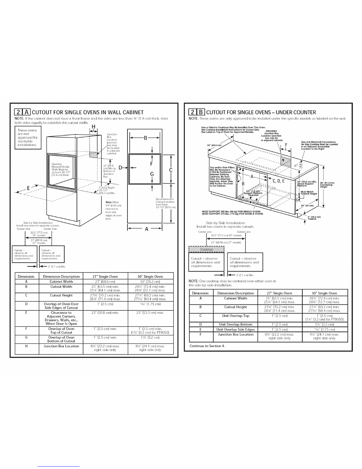
INSTALACIONES DE HORNO UNICO
El horno unico puecle instalarse solo en un gabinete o sobre un cajon calentador. El homo Linico tambien
puede instalarse debajo de un mostrador de encimera o debajo de las estufas especificadas. Yea la
etiqueta de la parte superior del homo para consultar los modelos aprobados.
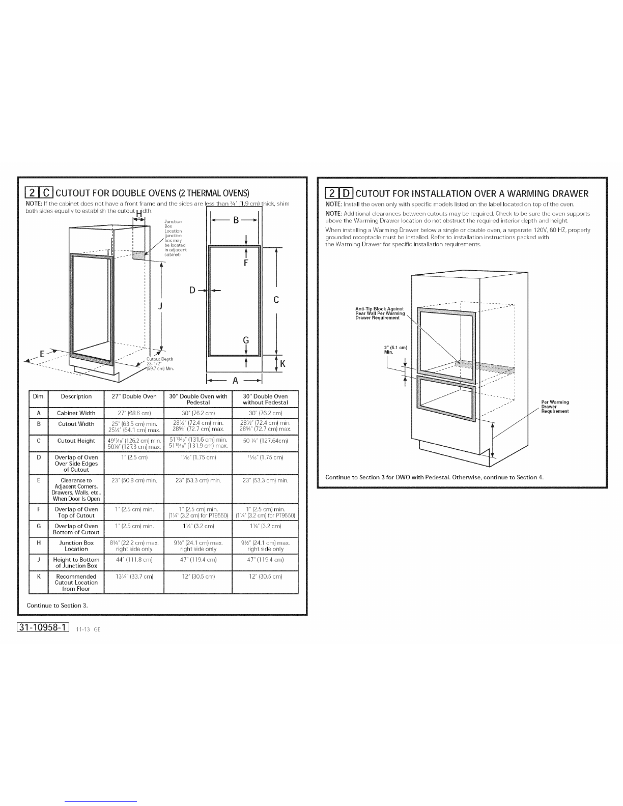
INSTALACIONES DE HORNO DOBLE
Puede instalarse un horno doble solo en un gabinete o sobre un cajon calentador. Yea la etiqueta de la
parte superior del horno para consultar los modelos aprobados.
IMPORTANTE: Siempre consulte las instrucciones de instalaciones individuales enviadas con cada producto
para requerimientos especificos.
IZi PREPARELA ABERTURA
NOTA: Si el gabinete no cuenta con un rondo solido,
deben instalarse dos abrazaderas o guias para
soportar el peso del homo. Para hornos Qnicos, las
guias o abrazaderas deben soportar 200 Ibs (91 kgs).
Para hornos dobles, las guias o abrazaderas deben
soportar 375 Ibs (170 kgs).
NOTA: Si mareas, imperfecciones o la abertura
resultaran visibles sobre el homo instalado, puede
set necesario agregar cunas de madera bajo las
guias y el reborde frontal hasta eubrir las mareas
o la abertura.
NOTA: Si el gabinete no euenta (:on un armazon
frontal y los lados son menores a un grosor de 3/4"
(1,9 cm), coloque cunas uniformemente sobre ambos
lados para establecer al aneho de la abertura.
Abrazaderas
adecuadas
para sostener
las gums
Gu_as de 2"x 4" (5 cm x 10 cm)
oequivalentes anivel con
el rondo del recorte
y niveladas
costados de _abertura

F'_ ABERTURAPARAHORNOS[INICOSENUNGABIENTEDEPARED
NOTA: Si el gabinete no cuenta (:on un armazon frontal y los lados son menores a un grosor de 3/4" (1,9 cm),
coloque cutlas uniformemente sobre ambos lados para establecer al ancho de la abertura.
Estos hornos
no estan
aprobados
para
instalaciones
apilables.
......
La abertura
entre las paredes
nternas debe ser
Linea central Linea central
k 30.5"£7r5cm) I
modelo30'r
I 2Tr(68.58cm)
!,r !
'rnodeB 77" "
Abertura cumpla | Abertura cumpla
con todas hs 1 con todas hs
dimensiones y dimensiones y
requerimientos, requerimientos,
_j J_ 2 'r (5rl cm) rain,
Ubicancion
de h caja de
conexiones
(h cajade
conexiones
/puede hallarse
en ungabinete
adyancente)
'1 _2" (55,9 CR]) Ur_ _
nin, basra la
I parle inferior
de ]a caja de
' conexiones
23 1/2"
(59,7cm) minimo
Nota: Deje
1/4" (0.64 cm)
de espacio
des@ los
extremos
laterabs de
la puerta del
horno
t
F
G
t
m
A
C
w
Ubicancion
recomendada
de la abertura
desde el piso
32 1/2"(826 cm}
1_2
Dimension Descripcion de la dimension Horno unico de 27" Homo unico de 30"
A Ancho del gabinete 27" (68,6 cm) 30" (762 cm)
B Ancho de la abertura 25" (63,5 cm) min. 28Z" (72,4 cm) min.
25X" (64,1 cm) max. 28W?' (72,7 cm) max.
C Altura de la abertura 27W?' (70,2 cm) mJn. 27X" (69,2 cm) mJn.
28Z" (71,4 cm) max. 27%" (69,4 cm) max.
D Superposicion del horno 1" (2,5 cm) 1X6" (1,75 cm)
sobre los costados
laterabs de la abertura
E Espacio respecto 23" (50,8 cm) min. 23" (53,3 cm) min.
de esquinas adyacentes,
cajones, paredes, etc.,
cuando la puerta
esta abierta
F Superposicion de la 1" (2,5 cm) min. i;; (215 cm) rTlinl
parte superior del homo (1X" (3.2 cm) para PT9050)
de la abertura
G Superposicion de la 1" (2,5 cm) min. 11/4"(32 cm)
parte inferior del homo
de [a abertura
H Ubicacion de la caja 8¾" (22,2 cm) max. 91/[ (24,1 cm) max.
de conexiones solo lado derecho solo lado derecho
ABERTURAPARAHORNOSI]NICOS=BAJOELMOSTRADORDEENCIMERA
NOTA: Estos hornos solo pueden instalarse bajo los modelos especlficos como se indica en la etiqueta
de la unidad.
Pueden instalarse estufas agas o elOctricas sobre este homo,
Ver las instrucciones de instalaci6n de la estufa para el
tamaSo de la aberlura,
Ver la etiqueta de la parle superior del homo para Ublcacibn de la caja
modelos aprobados, de conexiones de
240V/208V
(la caja de conexiones
puede haUarse en un
gabinete adyacente)
25" (53,5 cm) FLas conexiones de gas
yelOctricas para estufas
agas deben ubicarse en
una ubicaciOn adyacente
accesible sobre la derecha,
DEBE PODER SOSTENER 200 LBS, (90 kg) PARA HORNOS UNICOS
DEBE PODER SOSTENER 375 LBS, (170 kg) PARA HORNOS DOBLES
Instalaciones lado a lado
Instale dos hornos en aberturas separadas.
Linea central Linea central
!
30.5"(77.5cm) modelo30'r _'_i
27"(6858cm) modelo27" I
I
|
Abertura - cumpla _ Abertura - cumpla
(:on todas las l (:on todas las
dimensiones y dimensiones y
requerimientos, requerimientos.
_l _ 2 'r (5r_ err,)Mir,
NOTA: Una estufa puede centrarse sobre cualquier
homo en la instalaciOn de lado a lado.
22" (55,9 cm) rain. 36" (9t,4 cm)
sobre la plataforma Altura del mostrador
de encimera
4" (10,2 cm)
_ Placa de protecci6n
Dimension Descripcion de la dimension Homo unico de 27" Homo unico de 30"
A Ancho del gabinete 25" (63,5 cm) min. 28Z" (72,4 cm) min.
25X" (64,1 cm) max, 28_?' (72,7 cm) max,
B Altura de la abertura 27_?' (70,2 cm) min. 27X" (69,2 cm) min.
28Z" (71,4 cm) max, 27:'A{;" (69,4 cm) max,
C Superposicion de la 1" (2,5 cm) 1" (2,5 cm)
unidad en parte superior (1X" (3.2 cm) para PT9050)
D SuperposiciOn de la 1" (2,5 cm) 11/4"(32 cm)
unidad en parte inferior
E SuperposiciOn de la 1" (2,5 cm) 11A6"(1,75 cm)
unidad en costados laterales
F Ubicacion de la caja 8¾" (22,2 cm) max. 91/[ (24,1 cm) max.
de conexiones solo lado derecho solo lado derecho
Continue en la seccion 4.

[=2T_ ABERTURA PARA HORNOS DOBLES(2 HORNOS TERMICOS)
NOTA: Si el gabinete no cuenta (:on un armazon frontal y los lades son menores a un grosor de 3/4" (1,9 cm),
coloque cu¢las uniformemente sobre ambos lades para establecer al ancho de la abertura.
Ejn_--_?;
Ubicacion
de la ca]a de
conexiones (b caja
de conexiones
puede hallarse
en un gabinete
adyacente
J
Profundidad de la
:_.._ abertura 23-1/2'r
_ _(59,7 cm)mirfimo
_.=====-- B ======_
f
F
G
f
m
L-K
Dim. Descripcion Homo doble de 27" Homo doble de 30" Homo doble de 30"
con pedestal sin pedestal
A Ancho del gabinete 27" (68,6 cm) 30" (76,2 cm) 30" (76,2 cm)
B Ancho de la abertura 25" (63,5 cm) min. 281_'' (72,4 cm) min. 281½" (72,4 cm) min.
251/4" (64,1 cm) max. 28_" (72,7 cm) max. 28_" (72.7 cm) max.
C Altura de la abertura 4911A6'' (126,2 cm) rain. 511_6" (131,6 cm) rain. 50 V4" (127,64cm)
501/_'' (127,3 cm) max. 511%6" (131,9 cm) max.
D Superposicion del 1" (2,5 cm) 11A6"(1,75 cm) 11_6"(1,75 cm)
homo sobre los
costados laterales de
la abertura
E Espacio respecto de 23" (50,8 cm) rain. 23" (53,3 cm) rain. 23" (53,3 cm) rain.
esquinas adyacentes,
cajones paredes, etc.,
cuando la puerta esta
abierta
F Superposicion de la 1" (2,5 cm) min. 1" (2,5 cm) min. 1" (2,5 cm) min.
parte superior del (1¾" (3.2 cm) para (11A" (3.2 cm) para
homo de la abertura PT9550) PT9550)
G Superposicion de 1" (2,5 cm) rain. 1¾" (3,2 cm) 11A"(3,2 cm)
la parte inferior del
homo de la abertura
H Ubicacion de la caja 8¾" (22,2 cm) max. 91½'' (24,1 cm) max. 91_'' (24,1 cm) max.
de conexiones solo lade derecho solo lade derecho solo lade derecho
] Altura hasta la parte 44" (111,8 cm) 4T' (119,4 cm) 4T' (119,4 cm)
inferior de la caja de
conexiones
K Ubicacion 131A'' (33,7 cm) 12" (30,5 cm) 12" (30,5 cm)
recomendada de la
abertura desde el piso
Continue en la seccion 3.
31-10958-1 I 11-I:_GE
|rDl ABERTURA PARA INSTALACION SOBRE UN CA.ION
CALENTADOR
NOTA: Instaleelhomo solo con losmodelos especificoslistadosen laetiqueta ubicada
en laparte superiordel homo.
NOTA: Pueden necesitarse espacios adicionalesentre lasaberturas.Verifiqueque lossoportes
del homo sobre la ubicacion de (:_joncalentador no obstruyan laprofundidad y altura interiores
requeridas.
Cuando instaleun (>_joncalentador debajo de un homo _]nicoo doble,debe instalarse
un tomacorriente separado de 120V, 60 HZ con adecuada conexion a tierra.Consulte
las instruccionesde instalacionenviadas con el (>_joncalentador para requisitesespecificos
de instalacion.
B|oque anti-volcaduras
contra la pared trasera
seg_n requisite del
caj6n calentader
Ubicaci6n
recemendada
de la abertura
deade el piso
21 5/8" (54 9 cm)
2" (5,! cm)
rain.
Seg_n los requisites
del cajOn calentader
Continue a la Seccion 3 para conocer detalles del DWO con Pedestal. De otra forma, continue a la
SecciOn 4.

r_ INSTALACION DEL RIELCON PEDESTAL(30" HORNOS DOBLES
0NICAMENTE)
A. Coloque un riel (son pedestal en cada rodadura del gabinete o centrado en el lado opuesto de la
parte inferior del gabinete solido nivelado con el lateral de la abertura del gabinete. Ubique cada riel
de modo que la parte frontal de los mismos se encuentre detras del lado frontal de la abertura del
gabinete.
B. Realice agujeros de prueba y ac!junte los rieles a la rodadura o a la parte inferior del gabinete (son el
equipo provisto.

[_ REMOCION DE LA PUERTA (recomendada)
NOTA: La remocion de la puerta no es un requerimiento de la instalacion del producto, pero es una
comodidad adicional.
Para quitar la puerta:
A. Abra la puerta del homo en su totalidad.
B. Retire el soporte de la bisagra de la estructura frontal y dejelo a un lado. El
soporte de la bisagra debe set colocado nuevamente para un funcionamiento
apropiado de la puerta cuando est_i Liltima sea reinstalada.
C. Presione ambas trabas de la bisagra hacia abajo en direccion del marco de
la puerta basra destrabarlas. Para esto puede hacer falta un destornillador de
lados pianos, iNO LEVANTE LA PUERTA DE LA MANIJA!
D. Coloque las manos sobre ambos lados y cierre la puerta del homo hasta la
posicion de remocion (aproximadamente 1"-2" [2,5 cm-5,1 cm] de la posicion
de cierre).
E. Levante la puerta basra que los brazos de la bisagra hayan salido de las
ranuras. NOTA: La puerta del homo es muy pesada. AsegLirese de tenet un agarre firme antes de
levantar la puerta del homo de sus bisagras. Tenga cuidado una vez que haya quitado la puerta.
No deposite la puerta sobre la manija. Esto puede provocar abolladuras o rayones.
Soporte de la Bisagra
I /_ Poslclon destrabada de la bisagra
de la bisagra 1_ ,,
Brazo //\
de la blsagra _!_ La bisagra sale de la ranura
[_ REQUISITOS ELECTRICOS
ADVERTENCIA:Este aparato debe contar con una adecuada conexion a tierra.
ADVERTE NCIA: Parapreveni_unincendioodesca_gae,ectrica,nouti,iceuncab,e
de extension con este aparato.
-& ADVERTE NCIA: Parap_eveni_unadescargae,ect,ca,quitee,fusib,eoabrae,
interruptor de circuitos antes de comenzar la instalacion.
,_, ADVERTE NCIA: Unaconexioninadecuadadecab,eadodomesticodea,uminiocon
cables de cobre puede generar un peligro electrico o un incendio. Solo use conectores diser_ados para unir
cobre con aluminio y siga al pie de la letra el procedimiento recomendado del fabricante.
Recomendamos que un electricista calificado conecte el cableado electrico de su aparato. Despues
de la instalacion, solicite al electricista que le indique como desconectar la energia del aparato.
Usted debe usar un sistema electrico de fase tinica de 120/208 VAC o 120/240 VAC de 60 hercios. Si tiene
una conexion con cableado de aluminio, deben utilizarse conectores adecuadamente instalados para
utilizar con cableado de aluminio.
Vigente desde el 1 de enero de 1996, el Codigo Electrico Nacional requiere que las nuevas construcciones
(no existentes) utilicen una conexion de cuatro conductores a un homo electrico. Cuando instale un homo
electrico en una construccion nueva, una casa rodante, un vehiculo recreativo o un area donde los codigos
locales prohiben la conexion a tierra a traves de un conductor neutral, consulte la seccion sobre conexiones
en circuito derivado de cuatro conductores.
Consulte alas empresas de servicio pt_blico sobre los codigos electricos que se aplican en su area. No
realizar el cableado de su homo de acuerdo con los codigos vigentes puede provocar una situacion
peligrosa. Si no existen codigos locales, el cableado y fusibles de su horno deben cumplir con el Codigo
Electrico Nacional, NFPA N° 70, tiltima edicion, disponible en National Fire Protection Association (Asociacion
Nacional de Proteccion contra Incendios).
[_ REQUISITOS ELECTRICOS (CONT.)
Este aparato debe recibir el voltaje y frecuencia adecuados, y debe conectarse a un circuito derivado
individual con adecuada conexion a tierra, protegido por un interruptor de circuitos o fusible. Ver la placa de
clasificacion ubicada en el armazon del homo para determinar la clasificacion del producto.
Rating Plate
Location ..............................;
La placa de clasificacion se encuentra en el reborde
lateral del homo.
Utilice la tabla de abajo para determinar la proteccion de circuito dedicado minima recomendada:
ClasJfJcacion Tamaflo de circuito
de KW Clasificacion de KW recomendado
240V 208V (dedicado)
<4,8 KW <4,1 KW 20 Amp
4,9 KW-7,2 KW 4,2 KW-6,2 KW 30 Amp
7,3 KW-9,6 KW 6,3 KW-8,3 KW 40 Amp
9,7 KW-12,0 KW 8,4 KW-IO,4 KW 50 Amp
NO acorte el conducto flexible. La abrazadera del alivio de tension del conducto debe estar bien stJjeta a la
caja de conexiones y el conducto flexible debe estar bien stJjeto a la abrazadera. Si el conducto flexible no
entra dentro de la abrazadera, no instale el homo hasta obtener una abrazadera del tamano adecuado.
Los 3 cables de energia suministrados con este aparato son adecuados para conexiones con cableados
domesticos de calibre mayores. La aislacion de estos 3 cables esta clasificada a temperaturas mucho mas
elevadas que la clasificacion del cableado domestico. La capacidad
de transmitir corriente del conductor esta determinada pot el calibre del cable y la clasificacion
de temperatura de la aislacion alrededor del cable.

[_ REALICE LAS CONEXIONES ELECTRICAS
A ADVERTENCIA: esconecto,aenerg,ade,pane,dese vic,ob,oq.eo,osmodios
de desconexion para evitar el accionamiento de la energia de manera accidental. Cuando los medios
de desconexion de servicio no pueden bloquearse, coloque sobre el panel de servicio un dispositivo de
advertencia bien visible, como una etiqueta.
Coloque el homo sobre una mesa o plataforma en forma nivelada con la abertura. Para un homo unico,
la plataforma debe soportar 200 Ibs. (91 kg); para un homo doble, la plataforma debe soportar 375 Ibs.
(170 kg). Conecte el conducto flexible a la caja de conexiones electrica como se indica abajo*. Posicione
el conducto de modo tal que se apoye detras de la unidad en un circulo natural cuando el homo sea
instalado. Tendra que comprar una abrazadera para alivio de tension apropiada para completar la conexion
del conducto a la caja de conexiones. Caja de conexiones
Conducto
Coloque el homo
en un soporte para
ayudar a la conexion del
conducto
La abrazadera del alivio
de tension (no incluido)
debe usarse en la c_ja de
conexiones
_[os hornos vienen equipados con un conducto de 40" de Iongitud, Si desea un conducto mas largo, puede haber uno
disponible para su modelo, Para verFicar la disponibilidad o solicitar piezas, Ilame al 1,800,G[i.CARES,
A. Conecte el conductor a tierra del homo con el (:able neutral (blanco)
en rizo al neutral del circuito derivado (blanco o gris) utilizando un
tapon de alambre.
B. Conecte el cable rojo del homo al (:able ro.jo del circuito derivado y el
(:able negro del homo al (:able negro del circuito derivado de acuerdo
con los codigos locales, utilizando tapones de alambre.
C. Instale la tapa de la c_ja de conexiones.
F_ CONEXION DEClRCUITO DERIVADO DE TRESCONDUCTORES
NOTA: Si los cables domesticos son conductores de aluminio,
vet la ADVERTENCIA de la seccion 5, Requisitos electricos.
Cuando conecte un circuito derivado de tres conductores,
si Io permiten los codigos locales:
bles a
L - n_utrales
_dl _ Tapa. de
lacaja ae
conexiones
_'l CONEXION DE ClRCUITO DERIVADO DE CUATRO
CONDUCTORES
NOTA: Si los cables domesticos son conductores de aluminio, vet la ADVERTENCIA
de la seccion 5, Requisitos electricos.
A. Corte el (:able neutral (blanco) del conector de engarce.
Pele el cable neutral (blanco) para exponer la Iongitud correcta
del conductor.
B. Conecte el cable a tierra del artefacto (verde o cobre)
de acuerdo (:on los codigos locales. Si el conductor a tierra de la
residencia es de aluminio, vet ADVERTENCIA de la seccion 5.
C. Conecte el (:able neutral (blanco) del homo (:on el neutral
de circuito derivado (blanco o gris) de acuerdo (:on codigos
locales, utilizando un tapon de alambre.
D. Conecte el (:able rqjo del homo al (:able rqjo del circuito derivado
y el cable negro del homo al cable negro del circuito derivado de
acuerdo (:on los codigos locales, utilizando tapones de alambre.
NOTA: Si los cables rojos, negros o blancos son conductores de
aluminio, vet ADVERTENCIA de la seccion 5.
_ble a
Tapa de
la caja de
conexiones
E. Ilnstale la tapa de la c_ja de conexiones.
[_] DESUCE EL HORNO DENTRO DE LA ABERTURA
• Levante elhorno dentro
de la abertura del gabinete utilizando
el homo abierto como agarre, Con
cuidado empuje contra el armazon
frontal del homo, No presione sobre
los bordes externos,

ri_ INSTALE EL HORNO
A ADVERTENCIA:
Deben utilizarse tornillos de rnontaje. Si no Io hace,
el horno puede caer del gabinete, Io que provocaria
una lesion grave.
NOTA: Durante el montaje del homo, aseg_]rese
de que no haya danos sobre la]unta del homo,
que alina el extremo de la cavidad del homo
NOTA: Antes de perforar los orificios piloto,
asegLirese de que el homo se encuentre
en la posicion final de la abertura y centrado.
NOTA: Si el gabinete es de placa de particulas,
deben utilizarse tornillos #8 x 3/4" para dicho
material. Estos pueden adquirirse en cualquier
ferreteria.
A. Perfore a traves de los orificios de montaje
(superiores e inferiores) del reborde lateral
para los tornillos de mont_qje #8 provistos.
B. Asegure el gabinete del homo (.'on los tornillos
provistos.
Ubicaciones
de los
de montaje
las ubicaciones
pueden variar)
ih
Los tornillos
deben
hallarse a
un minimo
de ¼"
(6 mm) desde
el frente de
la abertura.
INSTALACION DEL REBORDE INFERIOR
• Una vez instalado el homo, ac!junte el borde inferior a traves de sus agL_jeros de montaje frente al
soporte vertical, utilizando los dos tornillos con cabeza recortada provistos. El labio de la cubierta
inferior debera set ubicado debajo de la brida de la parte inferior del conducto de aire.
Instalaciones SWO y DWO sin pedestal
DWO sin pedestales
1
IMPORTANTE: Siesta unidad alguna vez se quita del gabinete o si el homo se quita de servicio, el |
reborde inferior debe quitarse antes o el reborde sufrira danos. l

GUiA DE INSTALACION DE LA ESTANTERiA DEL HORNO (SI
CORRESPONDE)
A. Ubique el equipo de montaje de la guia del homo incluida.
B. Posicione el conducto de modo tal que se apoye detras de la unidad en un circulo natural cuando el
homo sea instalado.
C. Instale las guias usando las 8 tuercas de montaje provistas.
Imagen de la guia
de la estanteria
en su lugar
correspondiente.
COMO VOLVER A COLOCAR LA PUERTA DEL HORNO
NOTA: La puerta del homo es pesada. Puede necesitar ayuda para levantar la puerta Io suficiente
como para deslizarla dentro de las ranuras de la bisagra. No levante la puerta de la manija.
A. Levante la puerta del homo tomandola de ambos lados.
B. Con la puerta en el mismo angulo de la posicion de remocion
(aproximadamente 1"-2" [2,5 cm-5,1 cm] desde la posicion de cerrado),
introduzca la muesca del brazo de la bisagra dentro del extremo inferior de
la ranura de la bisagra. La ranura del brazo de la bisagra debe estar bien
colocada en la parte inferior de la ranura.
C. Abra la puerta pot completo. Si la puerta no se abre pot completo, la
muesca no est_J bien colocada en el extremo inferior de la ranura.
D. Presione las trabas de la bisagra hacia arriba contra el armazon frontal de
la cavidad del homo, hasta alcanzar la posicion de trabado.
IE. Reemplace el soporte de la bisagra. El soporte de la bisagra debe set
colocado nuevamente para un funcionamiento apropiado de la puerta.
F. Cierre la puerta del homo.
Bisagra en _
la posicion !1_ /'_
de trabado _
Ranura de la _ k...-'_ X_
bisagra bien J II _"'_i L_'
colocada en la" II _"\
parte inferior de_"_. "-..
la ranura de la I'_ \ "_ '-.
bisagra
Soporte de la Bisagra
Lado _ Brazo
inferiorde ' delabisagra !__l_
Ranura de la bisagra \
[_1 LISTA DE CONTROL FINAL DE LA INSTALACION
• Verifique que el interruptor de circuitos se encuentre cerrado (RESET)o que los fusibles del circuito
se hayan reemplazado.
• AsegLirese de que haya suministro electrico en el edificio.
• Controle que se haya quitado todo el material de empaque y la cinta adhesiva. No quitar estos
materiales puede provocar dahos al electrodomestico una vez que el aparato se haya encendido y
las superficies se hayan calentado.
• Quite todos los elementos ubicados dentro del homo.
• Aseg_]rese de que los tornillos de montaje se encuentren instalados y nivelados con el reborde
lateral (vet seccion 10).
•Verifique que el reborde inferior este bien instalado (vet seccion 11).
•Asegurese de que la abertura inferior del conducto de aire de la unidad este libre de obstrucciones.
•Controle que las guias de los estantes del homo (si corresponde) esten instaladas de fiorma correcta
y que los estantes del homo funcionen de fiorma fluida.
LISTA DE CONTROL DE FUNCIONAMIENTO
• Accione la energia del homo (consulte el Manual del propietario). Verifique que las unidades
de horneado y asado y que todas las funciones de coccion operen bien.
•Vet el Manual del propietario para la lista de deteccion y solucion de problemas.
•Asegurese de que todos los controles del homo se encuentren en OFF (apagado) antes
de dejar el homo.
Other manuals for JK3000DF3WW
1
This manual suits for next models
19
Table of contents
Languages:
Other GE Oven manuals
Popular Oven manuals by other brands

Bosch
Bosch HEN301.1S instruction manual

Breville
Breville Compact Smart Oven BOV650 Instruction booklet

Event Furniture
Event Furniture 19037 Operating & safety guide

Cata
Cata CMD 8108 X Installation, use and maintenance instructions

CDA
CDA SC309 Series Manual for installation, use and maintenance

Oster
Oster 6204 Instruction booklet