Quick Operation Guide of Network Video Recorder
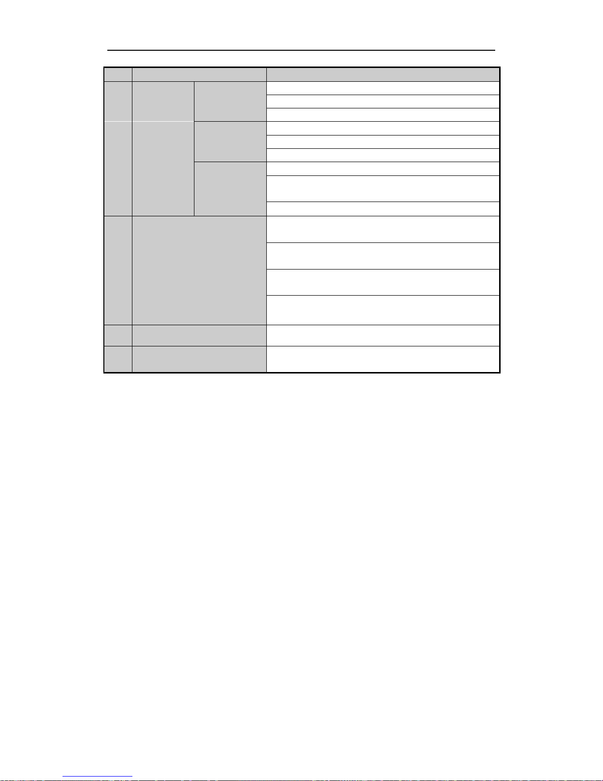
No. Name Function Description
REC/SHOT
Enter the Manual Record setting menu.
In PTZ control settings, press the button and then you can call a
PTZ preset by pressing Numeric button.
It is also used to turn audio on/off in the Playback mode.
PLAY/AUTO The button is used to enter the Playback mode.
It is also used to auto scan in the PTZ Control menu.
ZOOM+ Zoom in the PTZ camera in the PTZ Control setting.
A/FOCUS+
Adjust focus in the PTZ Control menu.
It is also used to switch between input methods (upper and
lowercase alphabet, symbols and numeric input).
EDIT/IRIS+
Edit text fields. When editing text fields, it will also function as
a Backspace button to delete the character in front of the cursor.
On checkbox fields, pressing the button will tick the checkbox.
In PTZ Control mode, the button adjusts the iris of the camera.
In Playback mode, it can be used to generate video clips for
backup.
Enter/exit the folder of USB device and eSATA HDD.
MAIN/SPOT/ZOO
M-
Switch between main and spot output.
In PTZ Control mode, it can be used to zoom out the image.
F1/ LIGHT
Select all items on the list when used in a list field.
In PTZ Control mode, it will turn on/off PTZ light (if
applicable).
In Playback mode, it is used to switch between play and reverse
play.
F2/ AUX
Cycle through tab pages.
In synchronous playback mode, it is used to switch between
channels.
MENU/WIPER
Press the button will help you return to the Main menu (after
successful login).
Press and hold the button for 5 seconds will turn off audible key
beep.
In PTZ Control mode, the MENU/WIPER button will start wiper
(if applicable).
In Playback mode, it is used to show/hide the control interface.
PREV/FOCUS-
Switch between single screen and multi-screen mode.
In PTZ Control mode, it is used to adjust the focus in
conjunction with the A/FOCUS+ button.
PTZ/IRIS-
Enter the PTZ Control mode.
In the PTZ Control mode, it is used to adjust the iris of the PTZ
camera.
8 Control
Buttons DIRECTION
The DIRECTION buttons are used to navigate between different
fields and items in menus.
In the Playback mode, the Up and Down button is used to speed
up and slow down recorded video. The Left and Right button
will select the next and previous record files.
6