EZ Digital DM-330SRS User manual

Test Equipment Depot - 800.517.8431 - 99 Washington Street Melrose, MA 02176 - FAX 781.665.0780 - TestEquipmentDepot.com


Before using the meter, you must read the following safety information of Maximum input
specification carefully.
V measurements : Below 1000VDC, 750VAC RMS
measurements : Below 500 (Fuse rating 250V)
10A measurements : Below 10A(Fuse rating 250V)
measurements : Below 600VAC/DC(1 minute)
Capacitance measurements : Below 600VAC/DC
Hz measurements : Below 250VAC/DC
BAT : Don't input the any voltage, current but battery voltage.
If you don't follow the safety information, DMM SET may be damaged.
And, it can cause a roaring noise or a fire.

INTRODUCTION -- - - - - - - - - - - - - - - - - - - - - - - - - - - - - - - - - - - - - - - - - - - - - - - 1
MULTIMETER SAFETY- - - - - - - - - - - - - - - - - - - - - - - - - - - - - - - - - - - - - - - - - - - 2
FEATURES - - - - - - - - - - - - - - - - - - - - - - - - - - - - - - - - - - - - - - - - - - - - - - - - - 4
HOW TO USE THE METER - - - - - - - - - - - - - - - - - - - - - - - - - - - - - - - - - - - - - 5
Input Terminals - - - - - - - - - - - - - - - - - - - - - - - - - - - - - - - - - - - - - - - - - - - - - - - 5
Function Selector Rotary Switch- - - - - - - - - - - - - - - - - - - - - - - - - - - - - - - - - - - 5
Pushbuttons - - - - - - - - - - - - - - - - - - - - - - - - - - - - - - - - - - - - - - - - - - - - - - - - 8
Digital display - - - - - - - - - - - - - - - - - - - - - - - - - - - - - - - - - - - - - - - - - - - - - - - 9
APPLICATIONS - - - - - - - - - - - - - - - - - - - - - - - - - - - - - - - - - - - - - - - - - - - - -10
Measuring Voltage (AC/DC) - - - - - - - - - - - - - - - - - - - - - - - - - - - - - - - - - - - - -10
(continued on page ii)
CONTENTS
TITLE PAGE

Measuring Current (AC/DC) - - - - - - - - - - - - - - - - - - - - - - - - - - - - - - - - - - - - -11
Me as ur in g Re si st an ce - - - - - - - - - - - - - - - - - - - - - - - - - - - - - - - - - - - - - - - - - 1 2
Tra ns is to r hF E Test - - - - - - - - - - - - - - - - - - - - - - - - - - - - - - - - - - - - - - - - - - - - - 1 3
Diode Test - - - - - - - - - - - - - - - - - - - - - - - - - - - - - - - - - - - - - - - - - - - - - - - - - - -14
Co nt in ui ty Tes t - - - - - - - - - - - - - - - - - - - - - - - - - - - - - - - - - - - - - - - - - - - - - - -1 5
Battery Test - - - - - - - - - - - - - - - - - - - - - - - - - - - - - - - - - - - - - - - - - - - - - - - - -16
Measuring Frequency - - - - - - - - - - - - - - - - - - - - - - - - - - - - - - - - - - - - - - - - - -17
Measuring Capacitance- - - - - - - - - - - - - - - - - - - - - - - - - - - - - - - - - - - - - - - - -19
In ne r Ba tt er y Vol ta ge C he ck - - - - - - - - - - - - - - - - - - - - - - - - - - - - - - - - - - - - 2 0
MAINTENANCE - - - - - - - - - - - - - - - - - - - - - - - - - - - - - - - - - - - - - - - 21
Calibration/ Replcement - - - - - - - - - - - - - - - - - - - - - - - - - - - - - - - - - - - - - -21
Battery & Fuse Replcement - - - - - - - - - - - - - - - - - - - - - - - - - - - - - - - - - 22
SPECIFICATIONS - - - - - - - - - - - - - - - - - - - - - - - - - - - - - - - - - - - - - - - - - - - - 23
Sp ec if ic at io ns ( DM -3 31 , 33 2) - - - - - - - - - - - - - - - - - - - - - - - - - - - - - - - 2 3
Specifications (DM-333, 334) - - - - - - - - - - - - - - - - - - - - - - - - - - - - - - - - - - 26
CONTENTS, continued
TITLE PAGE

INTRODUCTION
NOTE
All material in this manual applies to the DM-330SRS
unless otherwise indicated.
This meter has been designed and tested according to
EN 61010-1, Safety Requirements for Electronic
Measuring Apparaturs.
This manual contains information and warnings which
must be followed to ensure safe operation and retain the
meter in safe operation and retain the meter in safe
condition.
HOLSTER (Option)
The meter comes with a snap-on holster that absorbs
shocks and protects the meter from rough handling.
You can also hang the meter on your belt for easy viewing
while probing.
The test leads may be snapped into the holster that allows
you to hold both the meter and probe tip with one hand.
WARNING
READ "MELTIMETER SAFETY" BEFORE USING THE
METER.
Your EAD Digital Multimeter (also referred to as the meter )
is a handheld instrument that is designed for use in the field,
laboratory and at home.
The meter combines the precision of a digital meter with the
speed and versatility of a high resolution.
The meter is powered by a 1.5Vx2 battery and has a rugged
case sealed against dirt, dust and moisture.
A snap-on holster protects the meter from rough handling.
After unpacking the meter, if you notice that the meter is
damaged or something is missing, contact the place of
purchase immediately. Save the shipping container and
packing material in case you have to reship the meter.
The higher input voltage than the maximum one can cause
the roaring noise by the spark gap included for protection.
1
INTRODUCTION

MULTIMETER SAFETY
Before using the meter, read the following safety
information carefully. In the manual the word
"WARNING" is used for conditions and actions that
pose hazards to the user, the word "CAUTION" is
used for conditions and actions that may damage
your meter.
The symbols shown in Figure 1 are used
internationally to denote the electrical functions
and conditions indicated.
Figure 1. international Electrical Symbols
SAFETY DESIGNED
This meter has the feature that warns the dangerous
mismatching between rotary switch's mode selection
position and jack terminal used, Buzzer sound if rotary
switch is not set to Amp mode (10A DC/AC) during
10A terminal which a detector is built in, pluged in by
test lead. To avoid accidentally applying voltage to
10A terminal, verify that red test lead is connected
to V input terminal before making voltage
measurement. This restriction ensures protection
against burns in the event that voltage is accidentally
applied between 10A and COM terminals.
v/ terminal is colored in red, COM terminal in black
and 10A terminal in Red to be recognized with easy
(refer to Fig.2).
Avoid working alone.
Inspect the test leads for damaged insulation
or exposed.
Select the proper function and range for your
measurement.
MULTIMETER SAFETY
2

0.000 00.00 0.000
Figure 2
* Using Effect (A):No plug in 10A JACK terminal.(Range selector : except 10A position)
(B):Performance good Measurement.
(C): Buzzer sound.
(mismatching) (mismatching)(Good)
MULTIMETER SAFETY
3

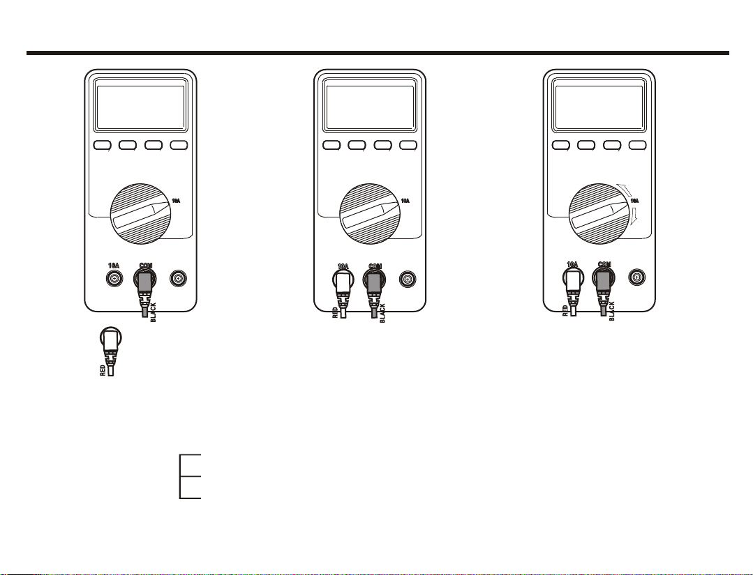
Disconnect the live test lead (Red) before
disconnecting the common test lead (Black).
Follow all safety procedures for equipment being
tested. Disconnect the input power and discharge
all high voltage capacitors through a protective
impedance before testing in the and functions.
When making a current measurement, turn the
power off before connection the meter in the circuit.
Check the meter fused before measuring current
transformer secondary or motor winding current.
An open fuse may allow high voltage build-up, which
is potentially hazardous.
To take a measurement, use the test lead probes to
make the proper contacts. Remember, insert the meter
in the circuit in parallel for voltage and in series for
current measurements.
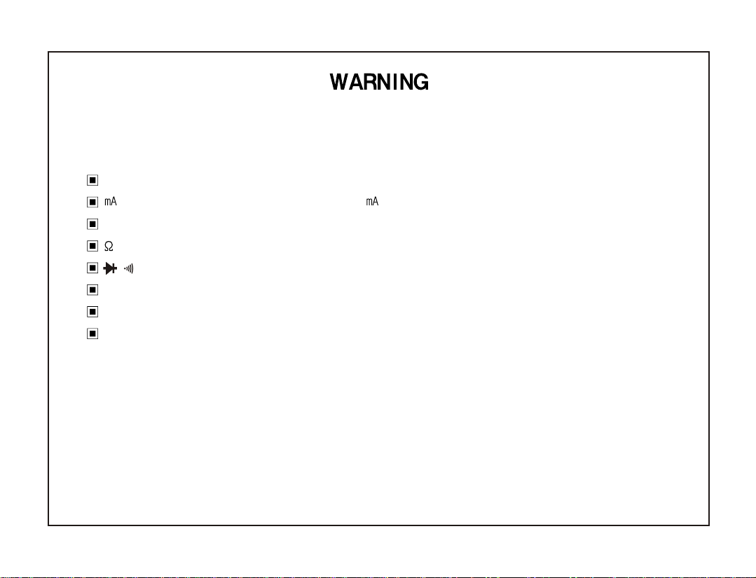
WARNING
TO AVOID ELECTRICAL SHOCK OR DAMAGE
TO THE METER, DO NOT APPLY MORE THAN
1000V BETWEEN COMTERMINAL AND EARTH
GROUND.
TO AVOID ELECTRICAL SHOCK, USE CAUTION
WHEN WORKING ABOVE 60V DC OR 30V AC
RMS, SUCH VOLTAGES POSE ASHOCK HAZARD.
FEATURES
3 Digit 4000 count LCD(DM-331, DM-332,DM-334)
3200 count LCD(DM-333)
Measurement rate Digital : 2 times/sec
Capacitance : 1 times/sec
Different colors of input terminals
Auto power About 30min(DM-331, DM-332, DM-334)
off About 10min(DM-333)
Low battery indication
Protection for input overload
Dual-slop integration A/D converter system.
Over range indication : Most-significant digit flickered
"OL" displayed (only, DM-333)
Battery life : Typical 500HRS with a regular battery
Temperatures
Operation : 0 ~ 40 (below 80% RH)
Storage : -10 ~ 60 (below 70% RH)
Guaranteed accuracy : 23 5
SAFETY
Certified by TUV Rheinland.
- EMC EMI : EN50081-1
EMS : EN50082-1
- Safety : EN61010-1
- Over voltage cat.
- pollution deg.
FEATURES
4

HOW TO USE THE METER
This section describes your meter and how to use it, For
ease of reference, each description is numbered and
keyed the illustration in page 29, 30 of this manual.
Input terminals
Item ~ describe the input terminals and the different
colors of input terminal allow you to have easy operation.
(See Table 1 for overload limits.)
10A Amperes Input Terminal
For current measurements (AC or DC) up to 10A
continuous when the function selector switch is in the
10A position.
COM Common Terminal (Black color)
Return terminal for all measurements.
Do not apply more than 1000V between The COM
terminal and Earth ground.
v/ Volts, Ohms, Continuity, Current(Ma), BAT,
Frequency, CAP, Diode test input Terminal (Red Color)
SOCKET Transistor hFE input terminal
Function Selector Rotary Switch
item describes functions that are selected by setting
the rotary switch. The meter is ready for normal operations
and will respond to the rotary switch and pushbuttons.
Volts AC Volts DC
Amperes AC Amperes DC
Resistance Battery Test
Diode Test TR hFE Test
Beeper Sound Continuity Test
Capacitance
Test
Frequency
Test
HOW TO USE THE METER
INPUT TERMINALS
5
Test Equipment Depot - 800.517.8431 - 99 Washington Street Melrose, MA 02176 - FAX 781.665.0780 - TestEquipmentDepot.com

Table 1. Input Terminals and Limits(DM-310SRS)
HOW TO USE THE METER
INPUT TERMINALS AND LIMITS
INPUT
TERMINALS
MIN DISPLAY
READING
MAX DISPLAY
READING
FUNCTION
RED BLACK
DM-331
332,334
DM-333
DM-331
332, 334
DM-333
MAXIMUM
INPUT
VV/ COM 0.1 0.1 1000V 1000V 1000VDC,750VAC
10A 10A COM 0.01A 0.01A 10.00A 10.00A 10A/250V
V/ COM 11399.9 325.9 400 /250V
V/ COM 0.1 0.1 39.99 32.59 600VAC/DC(1min)
CAP V/ COM
0.01
(DM-332)
-
39.99
(DM-332)
-600VAC/DC(1min)
Hz V/ COM
10Hz
(DM-332,334)
-
999.9
(DM-332,334)
-250VAC/DC
BAT V/ COM
0.001V
(DM-332,334)
-
39.99V
(DM-332,334)
-
Do not Apply any Voltage
or Current(only Battery)
V/ COM 600VAC/DC(1min)
6

Pushbuttons
Items ~ describe how to use the pushbuttons.
POWER ON/OFF (DM-331, 332)
Press the power button to turn on the meter.
MANUAL RANGING (DM-333, 334)
Press RANGE to select the manual range mode, then the
"AUTO" annunciator is Disappear (the meter remains in
the range it was in when manual ranging was selected).
In the manual range mode, each time for press range
button, the range increments, and a new value is
displayed. To exit the manual range mode and turn to the
auto ranging, press and hold down range mode and turn
to the auto ranging, press and hold down range sw for
2 seconds the "AUTO" annunciator turns back on.
MIN/MAX(DM-331, 332, 334)
Press MIN/MAX button to enter MIN/MAX recording mode.
The MIN/MAX are then reset to the present input in the
MIN/MAX recording mode, the MIN/MAX are stored in
memory.
Push MIN/MAX button to cycle through the MIN/MAX and
present readings at normal record speed. Charges to the
voltage, current or resistance inputs that last at least
100 milliseconds are recorded.
HOLD(display hold)
Press hold sw to toggle in and out of the touch hold mode.
In the touch hold mode, the "HOLD" annunciator is displayed
and the last reading is hold on the display.
When a new stable reading is detected, the beeper emits
a tone, and the display is automatically undated.
In the MIN/MAX recording mode, press "HOLD" to stop the
recording of reading,
press "HOLD" to stop display, press "HOLD" again to start
it.(DM-331, 332, 334)
DC/AC (DM-332, 333, 334)
Press Push the switch to measure AC voltage or AC current
in the voltage or current mode.
7
HOW TO USE THE METER
PUSHBUTTONS

REL(relative reading) (DM-331)
Press REL to enter the relative mode, zero the display,
and store the displayed reading as a reference value.
The relative mode annunciator "REL" is displayed.
Press and hold down REL for 2 seconds to exit in the
relative mode, the value shown on the LCD is always the
difference between the stored reference value and the
present reading. for example, if the reference value is
15.00V and the present reading is 14.10V, the display will
indicate -0.90V. If the new reading is the same as the
reference value, the display will be zero.
(DM-333)
Press push button switch to measure or in the
mode.
* Auto Power off
The meter will automatically shut itself off after
approximately 30min(DM-331, 332, 334) and 10min
(DM-333) after power on.
The meter can be turned back on by pushing Hold key
switch (DM-331, 332,334)and any key(DM-333).
HOW TO USE THE METER
PUSHBUTTONS
8

Digital and Analog display
1) DIGITAL DISPLAY
Digital reading are displayed on a 4000 count or 3200
count display with polarity indication and automatic point
placement. When the meter is turned on, all display
segments and annunciators appear briefly during a
selftest.
2) ANALOG DISPLAY
The analog display provides an analog representation of
readings and updates 20 times per seconds but it doesn't
operate at the capacitance function and the frequency
count mode.
3) AUTO AUTO-RANGE (DM-333, 334)
The meter is the auto-range mode and will automatically
select range with the best resolution.
The meter powers on in auto-range mode.
4) NEGATIVE POLARITY
Automatically indicates negative inputs.
When REL is enabled, indicates negative requests of math
calculations.
5) BEEPER
continuity test is enabled.
6) REL RELATIVE MODE(DM-331)
The value displayed is the difference between the present
measurement and the previously stored reading.
Probe resistance compensation for resistance
measurements can be achieved by using this mode.
7) MIN/MAX MODE
MIN/MAX value in MIN/MAX recording mode.
The value displayed is the maximum or minimum reading
taken since the minimum and maximum recording mode
was entered.
9
HOW TO USE THE METER
DIGITAL AND ANALOG DISPLAY

CC
KK
AA
LL
BB
CC
KK
AA
LL
BB
DD
RR
EE
DD
RR
EE
0.0000.000
0.0000.000
Figure 5-1. Measuring Voltage
APPLICATIONS
MEASURING VOLTAGE (AC/DC)
10
APPLICATIONS
This section discusses some common applications for your
meter, and alerts you to some considerations to keep in
mind when taking measurement.
Measuring Voltage (AC/DC)
To measure voltage, connect the black lead to common
terminal and red one to v/ terminal, and turn the rotary
switch to DCV or ACV range as Figure 5-1.
Connect the meter in parallel with the load or circuit under
test.
Each of AC/DC voltage ranges presents an input impedance
of approximately 10 in parallel with less than 50 . AC
voltage is AC-Coupled to the 10 input, and frequency
range is 50 to 400 (50~100 for 400 Range) and
50/60 for DM-333
Over range is being indicated by flickered figure "4" in display
(DM-331, 332, 334) and by character "OL" (DM-333)
Test Equipment Depot - 800.517.8431 - 99 Washington Street Melrose, MA 02176 - FAX 781.665.0780 - TestEquipmentDepot.com

CC
KK
AA
LL
BB
CC
KK
AA
LL
BB
DD
RR
EE
DD
RR
EE
Figure 5-2. Measuring Current
APPLICATIONS
MEASURING CURRENT (AC/DC)
11
0.000
0.000
Measuring Current (AC/DC)
If you do not know approximately what the current is,
connect the black lead to common terminal and red one to
10A input terminal first to see if you have a safe level for the
input (max. 400 ) terminal and turn the rotary switch to
DCA or ACA range as Figure 5-2.
Connect the meter in series with the load or circuit under test,
and note that the frequency range for AC current
measurement is 50 to 400 and 50/60 for DM-333
When measuring current, the meter's internal shunt resistors
develop a voltage across the meter's terminals called burden
voltage . This voltage drop is very low in your meter, but it
may affect precision circuits or measurements.
Over range is being indicated by flickered figure 4 in display.
(DM-331, 332, 334) and by character OL (DM-333)
WARNING
DO NOT APPLY THE VOLTAGE OF MORE THAN
60V DC OR 30V AC RMS.

CC
KK
AA
LL
BB
DD
RR
EE
4.000
Figure 5-3. Measuring Resistance
APPLICATIONS
MEASURING RESISTANCE
12
Measuring Resistance
To measure resistance, connect the black lead to common
terminal and red one to v/ terminal, and turn the rotary
switch to range as Figure 5-3. Connect the test leads
across the resistance under measurement.
CAUTION
Turn off power on the test circuit and discharge all
capacitors before attempting in-circuit resistance
measurements, If an external voltage is present across
a component, it will be impossible to take an accurate
measurement of the resistance of that component.
Due to the sensitive nature of 400 Ohm(DM-331, DM-332, DM-334), 320 Ohm(DM-333) range, a residual resistance
is present. This resistance will display itself, if the probes are shorted. This residual resistance is due to the lead, track
and switch resistance. To obtain measurement within the stated accuracy when using the 400 Ohm(DM-331, DM-332,
DM-334), 320 Ohm(DM-333) range subtract from your value the residual resistance reading.

CC
KK
AA
LL
BB
DD
RR
EE
0000
Transistor hFE Test (DM-312, 341)
Set rotary function switch to hFE range as Figure 5-4. insert
the leads (Emitter, Base, Collector) into the proper holes of
the socket on the front panel, according to transistor type
NPN or PNP.
The display reads approximate eFE value at the test condition
of Base current 2 and VCE 3V.
Figure 5-4.hFE Test
NOT USED
APPLICATIONS
TRANSISTOR hFE TEST
13

CC
KK
AA
LL
BB
DD
RR
EE
Figure 5-5. Diode Test
Diode Test
To perform a diode test, plug the black test lead to COM
terminal and the red one into v/ inputs, turn the rotary
switch to , and connect the test leads across the diode
under measurement as Figure 5-5.
The forward voltage drop is displayed in V unit and overload
(only, DM-333) or about 3.000V.
Test condition : Forward DC current (1 )
Reversed DC voltage (3.0V)
APPLICATIONS
DIODE TEST
14
0.600

CC
KK
AA
LL
BB
DD
RR
EE
Figure 5-6. Continuity Test
Continuity Test
Continuity testing verifies that circuit connections are intact.
To perform audible continuity tests, Turn the rotary switch to
the position.
Connect the black test lead to COM input terminal and the
red one to v/ terminal, and the leads across the resistance
or circuit under measurement as Figure 5-6.
Test resistance below 40 (DM-331, 332, 334) or 20
(DM-333) cause the meter to emit a continuous tone.
CAUTION
Turn off power on the test circuit and discharge all
capacitors before attempting continuity testing.
APPLICATIONS
CONTINUITY TEST
15
0.600
Test Equipment Depot - 800.517.8431 - 99 Washington Street Melrose, MA 02176 - FAX 781.665.0780 - TestEquipmentDepot.com
Table of contents
Other EZ Digital Multimeter manuals