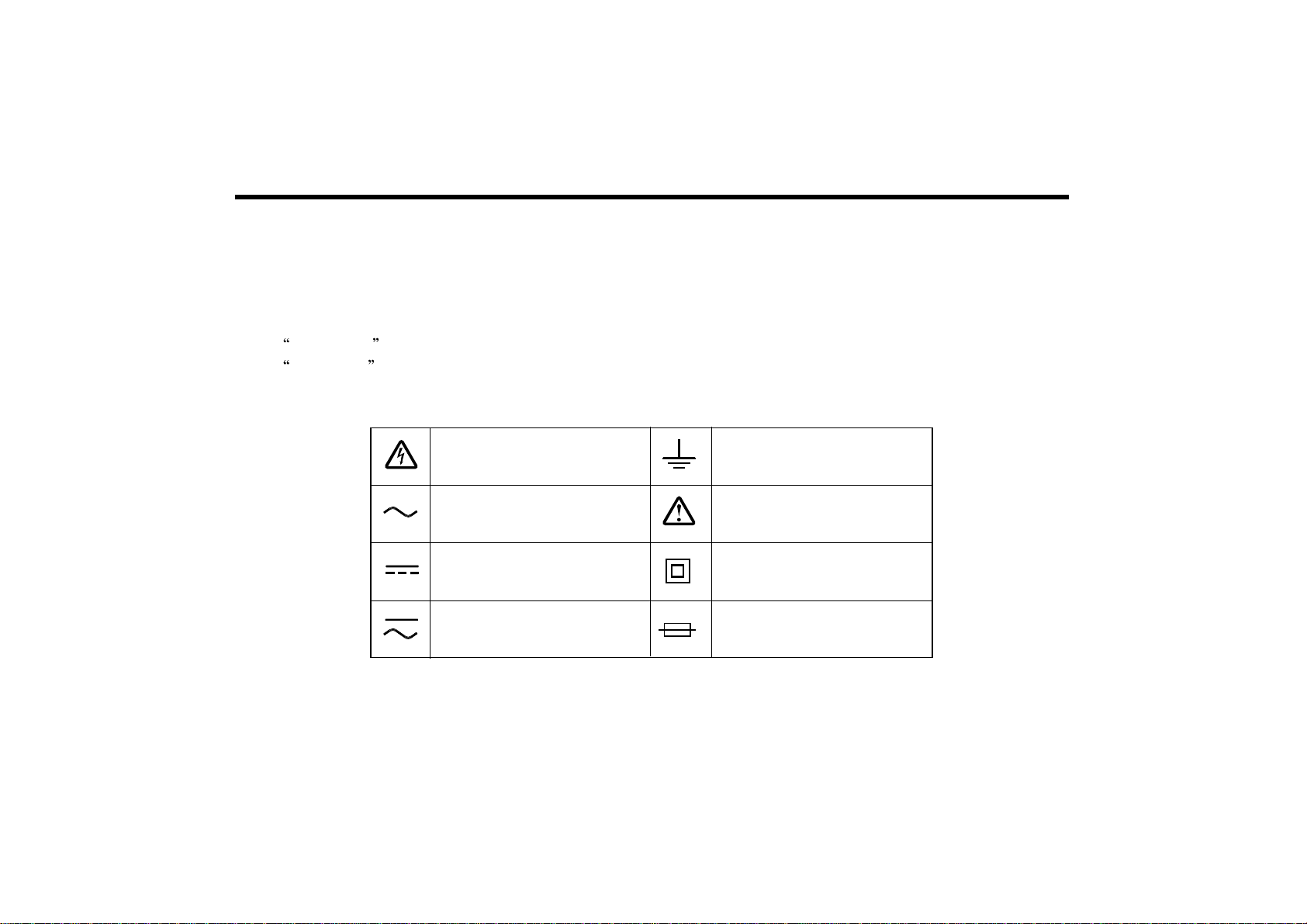
EZ Digital DM-530SRS User manual


DM-530SRS
DIGITAL MULTIMETER
Operation Manual
DIGITAL MULTIMETER

2
WARNING
Before using the meter, you must read the following safety information for
Maximum input specifications carefully.
Voltage measurements : Below 1000VDC, 750VAC RMS (DM-531/532)
True RMS (DM-531T/532T)
mA measurements : Below 500mA (Fuse rating 600V)
10A measurements : Below 10A (Fuse rating 600V)
measurements : Below 600V AC/DC (1 minute)
Capacitance : Below 600V AC/DC (1 minute)
Hz measurements : Below 600V AC/DC (1 minute)
If you don't follow the safety information, DMM SET may be damaged.

3
DECLARATION OF CONFORMITY
according to ISO/IEC Guide 22 and EN (45014)
Manufacturer's Name EZ Digital Co., Ltd
Manufacturer's Address #222-28, Nae-dong, Ojeong-gu Bucheon-si, Gyeonggi-do,
KOREA, 421-160
Declares that the product :
Product Name : DIGITAL MULTI METER
Model Numbers : DM-531, DM-532, DM-531T, DM-532T
Data : July. 05. 2001.
Conforms to the following product specifications :
Certified by TÜV Rheinland
Safety : EN 61010-1 :
(IEC 1010-1 : 1992,1010-2-031 )
EMC EN 50081-1 : 1992
EN 50082-1 : 1992
Supplementary Information :
The product herewith complies with the requirements of the Low Voltage
Directive 73/72/EEC and the EMC Directive 89/336/EEC.
Bucheon, Gyeonggi
Location cheol-young, Kim
Quality Assurance Manager

4
WARRANTY
This instrument is warranted against defects in material and
workmanship for a period of one year from the data of sale.
During the warranty period, EZD will repair or replace it which
prove to be defective. But warranty shall not apply to defects
resulting from improper or inadequate maintenance by buyer,
In this case, the repair will be billed at nominal cost.
For warranty service or repair, this instrument must be returned
to a service facility designated by EZD.
Buyer shall prepay shipping charges to EZD and EZD shall pay
shipping charges to return it to buyer.

5
CONTENTS
TITLE ....................................................................................................................... PAGE
INTRODUCTION ............................................................................................................ 7
MULTIMETER SAFETY ................................................................................................ 8
FEATURES .................................................................................................................... 10
HOW TO USE THE METER ........................................................................................ 10
Input Terminal ........................................................................................................... 11
Function Selector Rotary Switch ............................................................................... 12
Pushbuttons ............................................................................................................... 12
APPLICATION .............................................................................................................. 15
Measuring Voltage (AC/DC) ..................................................................................... 15
Measuring Current (AC/DC) ..................................................................................... 16

6
TITLE........................................................................................................................ PAGE
Measuring Resistance ............................................................................................... 17
Diode Test ................................................................................................................. 18
Continuity Test ......................................................................................................... 19
Measuring Frequency ............................................................................................... 20
Measuring Capacitance ............................................................................................ 22
TRUE RMS (DM-531T, DM-532T) ............................................................................. 23
Battery or Fuse Replacement (DM-531T, DM-532T) ................................................... 24
Battery or Fuse Replacement (DM-531, DM-532) ....................................................... 25
SPECIFICATION .......................................................................................................... 26

7
INTRODUCTION
NOTE
All material in this manual applies to the DM-530SRS unless otherwise indicated.
This meter has been designed and tested according to IEC 61010-1, UL 3111-1
Safety Requirements for Electronic Measuring Apparaturs.
This manual contains information and warnings which must be followed ensure
safe operation and retain the meter in safe condition.
HOLSTER
The meter comes with a snap-on holster that absorbs shocks and protects the meter
from rough handling. you can also hang the meter on your belt for easy viewing while probing
The test leads may be snapped into the holster that allows you to hold both the meter and probe tip with
one hand.
CLEANING
When you clean meter, you use a damp towel or cloth only.
INTERNATIONAL ELECTRICAL SYMBOLS ELECTRICAL UNITS OF MEASUREMENT
Caution Volts (V)
Double Insulation (Protection Class) Amps (A)
Ground Ohms ( )
Fuse Hertz (Hz)
Milli (m)
Micro ( )
Capacitance ( )

8
MULTIMETER SAFETY
MULTIMETER SAFETY
Before using the meter, read the following safety information carefully. In the manual the word
WARNING is used for conditions and actions that pose hazards to the user, the word
CAUTION is used for conditions and actions that may damage your meter. The symbols
shown in Figure 1 are used internationally to denote the electrical function and conditions indicated.
Figure 1. international Electrical Symbols
DANGEROUS
VOLTAGE GROUND
SEE EXPLANATION
DOUBLE
INSULATION
FUSE
AC-ALTERNATING
CURRENT
DC-DIRECT
CURRENT
EITHER
DC OR AC

9
SAFETY DESIGNED
V / terminal is colored in red, COM terminal in black and 10A terminal in RED
to be recognized With easy
Inspect the test leads for damaged insulation or exposed.
Select the proper function and range for your measurement.
Follow all safety procedures for equipment being tested. Disconnect the input power
and discharge all high voltage capacitors through a protective impedance before testing
in the and (DIODE) function.
When making a current measuring , turn the power off before connection the meter
in the circuit
Check the meter fused before measuring current trans-former secondary or motor winding
current. An open fuse may allow high voltage build-up, which is potentially hazardous.
To take a measurement, use the test lead probes to make the proper contacts. Remember,
insert the meter in the circuit in parallel for voltage and in series for current measurements.
WARNING
TO AVOID ELECTRICAL SHOCK OR DAMAGE TO THE METER, DO NOT APPLY MORE
THAN 1000V BETWEEN COM TERMINAL AND EARTH GROUND.
TO AVOID ELECTRICAL SHOCK, USE CAUTION WHEN WORKING ABOVE 60V DC OR
30V AC RMS / True RMS , SUCH VOLTAGES POSE A SHOCK HAZARD.

10
FEATURES
3 3/4 Digits - 4000 counts LCD
Different colors of input terminals
Auto power off - ( 30 minute )
Low battery indication
Protection for input overload : Most-significant digit flickered displayed
Battery life : Typical 500HRS with a regular battery
Temperatures
Operating : 0 ~ 40 (below 80% RH)
Storage : -10 ~ 60 (below 70% RH)
Guaranteed accuracy : 23 5
Installation Category (Overvoltage Category) : CAT
Relative Humidity : 0% to 80% @ (0 to 35 )
0% to 70% @ (35 to 45 )
Altitude : Operating - up to 2000m
Storage - 10000m
HOW TO USE THE METER
This section describes your meter and how to use it, For ease of reference, each description
is numbered and keyed the illustration in page 35 of this manual.

11
Input Terminal
Item describe the input terminals and different colors of input terminal allow you
to have ease operation (See Table 1 for overload limits.)
10A Ampere input Terminal - For current measurements(AC or DC) up to 10A continuous
(Red color) when the function selector switch is in 10A position.
mA/uA Ampere input Terminal (Red color)
COM - Common Terminal - Return terminal for all measurements. Do not apply more than
(Black color) 1000V between The COM terminal and Earth ground
V/ : Volts, Ohms, Continuity, Frequency, CAP, Diode Test input terminal (Red color)
Table 1. Input terminals and Limits
FUNCTION
V
10A
mA
uA
CAP
Hz
V/
10A
mA/uA
mA/uA
V/
V/
V/
V/
0.1mV
0.01A
0.01mA
0.1uA
0.1
0.001nF
1Hz
1000V
10.00A
399.9mA
3999uA
39.99M
39.99mF
399.9MHz
1000V DC, 750V AC
10A / 600V
400mA / 600V
400mA / 600V
600V AC/DC (1minute)
INPUT TERMINALS
RED BLACK
MIN DISPLAY
READING MAX DISPLAY
READING
MAXIMUM INPUT
COM
COM
COM
COM
COM
COM
COM
COM

12
Function Selector Rotary Switch
Item describes function that are selected by setting the rotary switch. The meter is ready
for normal operations and will respond to the rotary switch and pushbuttons.
Pushbuttons
Item describe how use the pushbuttons
POWER ON / OFF
Press the power button to turn on the meter
PEAK HOLD
In current and voltage measurement, this button performs a peak hold function. The peak hold mode
must be calibrated prior to use. To calibrate the peak hold, press the key until the meter displays
CAL Short the test leads to calibrate.
DC & AC Voltage Measurement
DC & AC Ampere Measurement
Resistance Measurement
Diode Test
Capacitance Measurement
Beeper Sound Continuity Test
Frequency Measurement
Hz

13
DATA HOLD
Press hold switch to toggle in and out of the touch hold mode. In the touch hold mode the
HOLD annunciator is displayed and the last reading is hold on the display.
FUNCTION
Press this switch to measure AC/DC voltage, AC/DC current, Resistance, Continuity, Diode test
selector button to turn on.
MAX / MIN
Press this switch to toggle between the minimum and maximum values. Pressing the button for
2 seconds to escape MIN / MAX mode.
V-Hz (DM-531/532)
This switch is used to quickly view the frequency during measuring the AC voltage or current.
Push V-Hz switch once the LCD is changed to display frequency. Push V-Hz switch again,
the LCD back to display the AC signal amplitude reading. in V-Hz mode, pressing RANGE key
switch does not change the frequency range. however, RANGE key switch changes the sensitivity
of frequency detection, if the input signal amplitude is less than 1% of full scale reading, the user
shall increase the sensitivity. pressing range switch in V-Hz mode also changes the full scale
range of the original voltage mode.

14
RANGE HOLD
Press RANGE to select the manual range mode, then the word AUTO will disappear
(the meter remains in the range it was in when manual range was selected). In the manual
range mode, each time you press range button, the range increases, and a new value is
displayed. To exit the manual range mode and turn to the auto ranging, press and hold down
range switch for 2 seconds the word AUTO will appear again.
RS-232C (DM532 / DM532T)
Measuring in the RS-232 port DATA pc mode Pc program is avaliable at EZ digital homepage Please
Download.
REL (DM531 / DM531T)
For resistance, frequency, capacitance measurements, this button enables the relative change function.
When pressed the value is stored, and all new measurements are displayed as their difference from
the stored value.
* Auto power off - The auto power off sign on the LCD panel indicates the meter is working in the
auto power off mode. if the meter idles for more than 30 minutes, the meter automatically turns the
power off. When this happens, the state of the meter is saved, the meter can be turned back on by
pushing any key switch or changing the rotary switch. The meter will give an alarm in 15 seconds
before the meter automatically turns the power off. To disable the auto power off function, power up
the meter while pressing either the range, REL or MAX/MIN switch.

15
APPLICATION
This section discusses some common application for your meter,
and alerts you to some things to keep in mind when taking
measurements.
Measuring Voltage (AC / DC)
To measure voltage, connect the black lead to common terminal
and red one to V/ terminal , and turn the rotary switch to
VHz range as Figure 5-1
Each of AC/DC voltage ranges presents an input impedance of
approximately 10 , AC voltage is AC-Coupled to the frequency
range is 40 to 400 .
* Over range is being indicated by flickered OL display
* Press this switch to measure AC voltage FUNC selector button
to turn on
Figure 5-1. Measuring Voltage

16
Measuring Current (AC / DC)
If you don't know what the current is, connect the black lead
to the common terminal and red one to the 10A input
terminal
first to see if you have a safe level for the input (max. 400
)
terminal and turn rotary switch to A range as Figure 5-2
Connect the meter in series with the load or circuit under
test,
and note that the frequency range for AC current
measurement is
40 to 400 .
* Over range is being indicated by flickered OL display
* Press this switch to measure AC voltage FUNC
selector button to turn on
* WARNING
DO NOT APPLY THE VOLTAGE OF MORE THAN
600V DC OR 600V AC RMS
Figure 5-2. Measuring current
R
E
D
B
L
A
C
K
R
E
D
B
L
A
C
K
R
E
D
B
L
A
C
K
R
E
D
B
L
A
C
K

17
Measuring Resistance
To measure resistance, connect the black lead to common terminal
and red one to V/ terminal, and turn the rotary switch to
range as Figure 5-3. Connect the test leads across the resistance
under measurement.
* CAUTION
Turn off power on the test circuit and discharge all capacitors
before attempting in-circuit resistance measurements, If an
external voltage is present across a component, it will be
impossible to take an accurate measurement of the resistance
of that component.
Due to the sensitive nature of the 400 range, a residual resistance is present. This resistance will display itself,
if the probes are
shorted. This residual resistance is due to the lead, track and switch resistance. To obtain measurement within the
stated accuracy when using the 400 range subtract from your value the residual resistance reading.
* Over range is being indicated by flickered OL display
R
E
D
B
L
A
C
K
Figure 5-3. Measuring resistance

18
Diode Test
To perform a diode test, plug the black test lead to the COM
terminal and the red one into the V/ input, turn the rotary
switch to (diode setting) and connect the test leads across the
diode under measurement as Figure 5-4.
* Press this switch to measure diode range selector button
The forward voltage drop is displayed in V unit.
Test condition : Forward DC current (2 mA)
Reversed DC voltage (1 V)
Figure 5-4. Diode test

19
Continuity Test
Continuity testing verifies that circuit connections are intact.
To perform audible continuity tests, turn the rotary switch
to the (continuity test) position.
* Press this switch to measure continuity range selector button
Test resistance below 35
* CAUTION
Turn off power on the test circuit and discharge all
capacitors before attempting continuity testing.
Figure 5-5. Continuity test
Table of contents
Other EZ Digital Multimeter manuals