ez-wheel 300 Series User manual

Electric wheels
Se
Instruction manual [EN]
Version A - 14/11/2022 –Translated from French

INSTRUCTION MANUAL
Electric wheels Series 300 & 10’’ version A
Page 2on 28
V-EN_14112022
Table of Contents
1. Preamble .......................................................................................................................................................................... 4
1.1 Important information about the manual .............................................................................................................. 4
1.2 Important notice..................................................................................................................................................... 4
2. Safety instructions............................................................................................................................................................ 4
2.1 Precautions for the use of ez-Wheel® products...................................................................................................... 4
2.2 Precautions for the use of the batteries ................................................................................................................. 5
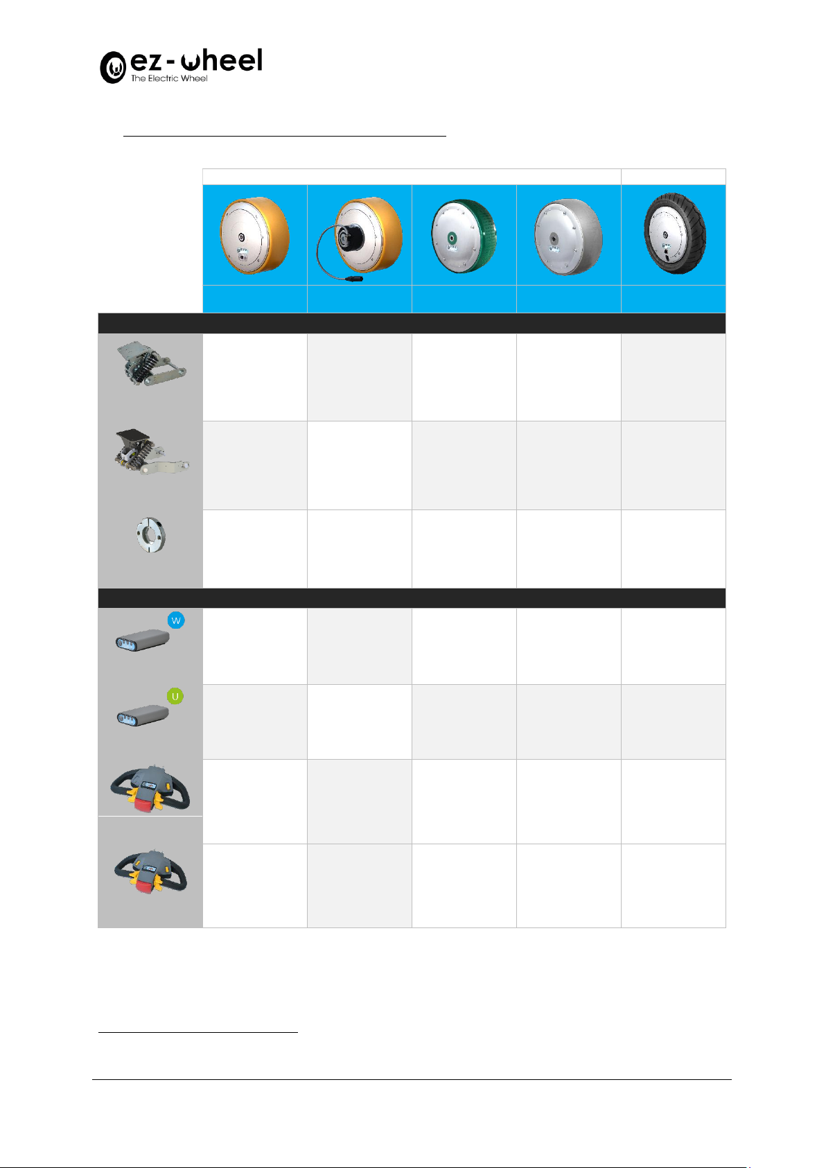
3. ez-Wheel® product overview and compatibility............................................................................................................... 6
4. Before use......................................................................................................................................................................... 7
5. Integration of the ez-Wheel® products............................................................................................................................. 7
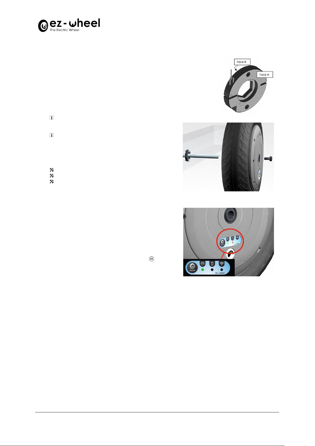
5.1 Mounting of the wheel on the axle......................................................................................................................... 7
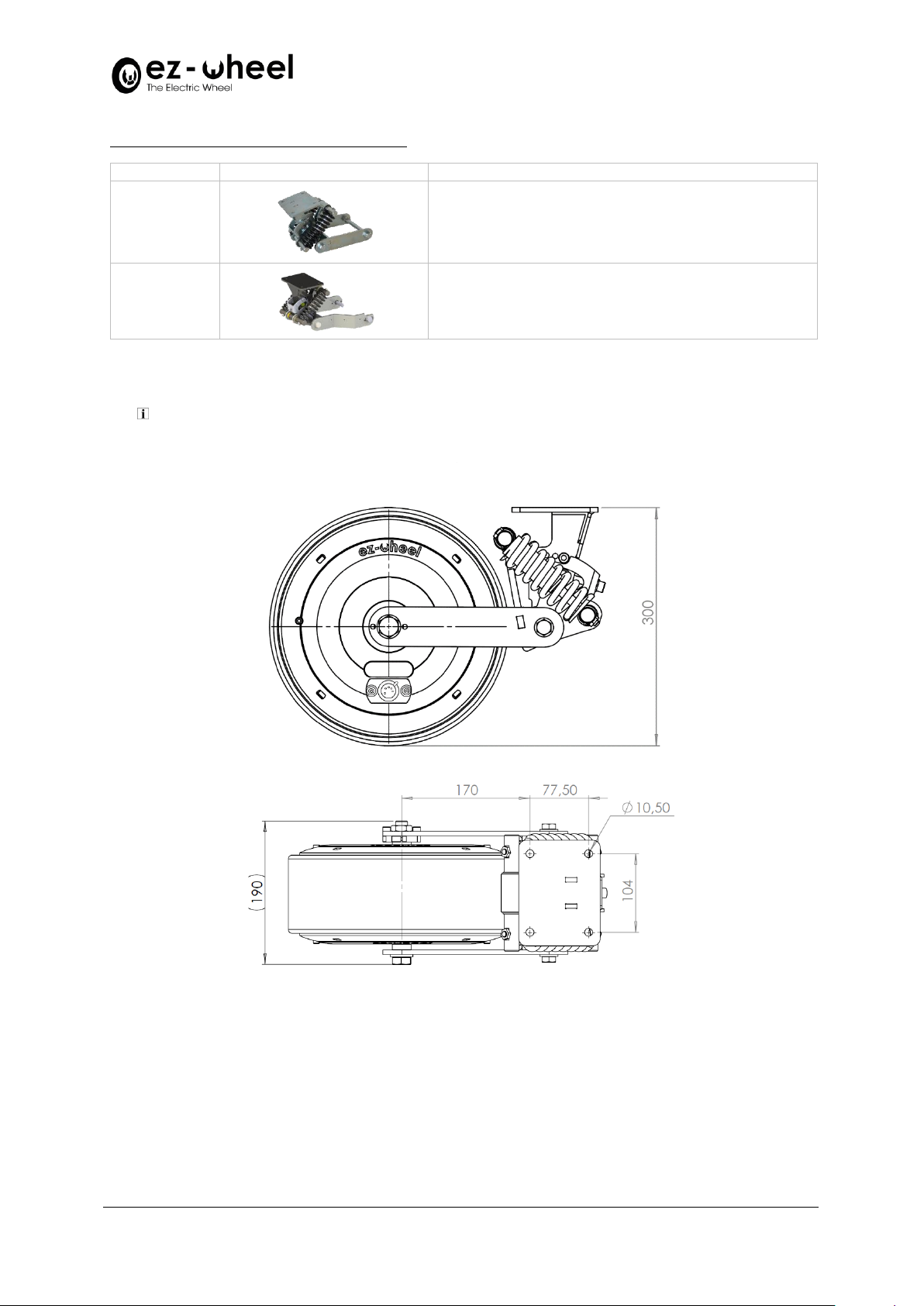
5.2 Mounting of the wheel to the application via an integration bracket .................................................................... 8
5.2.1 Size of the bracket/wheel assembly................................................................................................................... 9
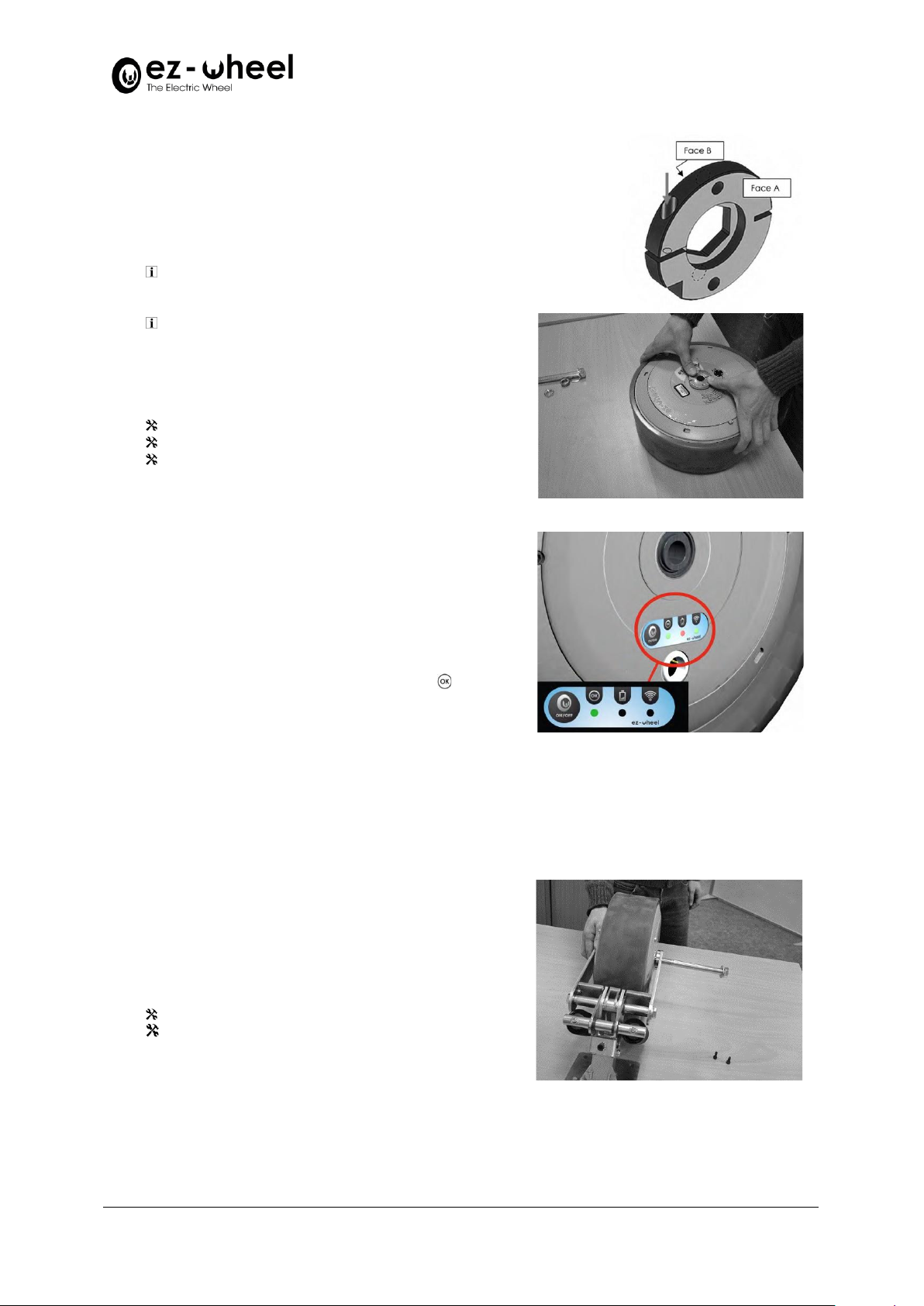
5.2.2 Integration of the anti-rotate ring on the wheel................................................................................................ 9
5.2.3 Fitting the wheel to the suspended bracket .................................................................................................... 10
5.2.4 Adjusting the tension ....................................................................................................................................... 11
5.2.5 Fixing the pre-assembled unit on the machine ................................................................................................ 12
5.3 Integration of directional controls ........................................................................................................................ 12
5.3.1 Integration of the tiller head............................................................................................................................ 13
5.3.2 Integration of the wireless interface box ......................................................................................................... 13
5.4 Setting of the system ............................................................................................................................................ 15
6. Starting up of the equipment ......................................................................................................................................... 15
6.1 Starting up of the tiller head................................................................................................................................. 15
6.1.1 Initial starting up of the tiller head................................................................................................................... 15
6.1.2 Use of the tiller head........................................................................................................................................ 16
6.2 Starting up of the wireless interface box .............................................................................................................. 16
6.2.1 Initial starting up of the wireless interface box................................................................................................ 16
6.2.2 Use of the wireless interface box..................................................................................................................... 17
7. Charging the ez-Wheel® products................................................................................................................................... 18
7.1 Charging the wheel ............................................................................................................................................... 18
7.1.1 Charging the wheel with charging connector................................................................................................... 18
7.1.2 Charging the wheel without charging connector ............................................................................................. 18
7.2 Charging the tiller head......................................................................................................................................... 20
8. Display ............................................................................................................................................................................ 20
8.1 Wheel display........................................................................................................................................................ 20
8.2 Wireless interface box display .............................................................................................................................. 20
8.3 Tiller head display ................................................................................................................................................. 21
9. Maintenance................................................................................................................................................................... 21
9.1 Maintenance of wheels with connectors.............................................................................................................. 21

INSTRUCTION MANUAL
Electric wheels Series 300 & 10’’ version A
Page 3on 28
V-EN_14112022
9.2 Maintenance of the stainless-steel wheels without connectors........................................................................... 21
9.3 Prolonged shutdown............................................................................................................................................. 22
9.4 Safety rules in relation to the batteries ................................................................................................................ 22
9.5 Incorrect use ......................................................................................................................................................... 22
9.6 Changing the wireless interface box batteries...................................................................................................... 22
9.7 Versions with tyres: changing a tyre ..................................................................................................................... 23
9.8 Versions with solid tyre......................................................................................................................................... 25
10. Contacting your dealer ................................................................................................................................................... 25
11. Troubleshooting ............................................................................................................................................................. 25
11.1 Wheel malfunctioning........................................................................................................................................... 25
11.2 Troubleshooting the wheel/wireless interface box assembly............................................................................... 25
11.3 Troubleshooting the wheel/tiller head assembly ................................................................................................. 27
11.4 Changing a tyre ..................................................................................................................................................... 28
11.5 System reset procedure........................................................................................................................................ 28
12. Product end-of-life.......................................................................................................................................................... 28
13. Declarations.................................................................................................................................................................... 28
13.1 Declaration of incorporation................................................................................................................................. 28
13.2 Declaration of CE conformity................................................................................................................................ 28

INSTRUCTION MANUAL
Electric wheels Series 300 & 10’’ version A
Page 4on 28
V-EN_14112022
1. Preamble
1.1 Important information about the manual
Important information –Read carefully
Additional information
Necessary tools
1.2 Important notice
CE Marking: within the European Economic Area, the machine equipped with an ez-Wheel®
electric drive shall be and remain compliant with the Machinery Directive 2006/42/EC.
The ez-Wheel® electric wheel is a partly completed machine as defined in the Machinery
Directive 2006/42/EC. This product is intended to be incorporated into an application and
may under no circumstances be put into operation before the application has been declared
in conformity with the provisions of Directive 2006/42/EC.
2. Safety instructions
2.1 Precautions for the use of ez-Wheel® products
This instruction manual contains the instructions to be followed for the installation and the maintenance of the ez-Wheel®
products.
All mechanical drawings that could serve for the installation of ez-Wheel® products are available on request.
All the accessories mentioned are available in the ez-Wheel® product guide.
Do not use ez-Wheel® products for other purposes or in other conditions than those
mentioned in the technical documentation.
Read and make sure you have understood the manual before using ez-Wheel® products.
Observe all the warnings and usage instructions in this manual.
Keep this manual for reference throughout the life of the product.
In the event of loss, you can obtain a copy of this manual on the ez-wheel.com website under
“Download center”.
If the product is transferred to another owner, make sure that the manual is transferred as
well.
The characteristics, descriptions, and illustrations in this document are applicable at the date
of publication.
ez-Wheel reserves the right to make any modifications and revisions to this document without
prior notice.
Product users obtain their own information on these modifications.
Precautions for the use of the wheel:
Always use a suitable charger.
Do not submerge the wheel.
Do not open the wheel.
Do not expose to a heat source.
Do not expose to fire.
Do not insert pieces of metal into the connector.
The product must under no circumstances be modified without authorization from ez-Wheel.

INSTRUCTION MANUAL
Electric wheels Series 300 & 10’’ version A
Page 5on 28
V-EN_14112022
Do not try to change the technical performance of the wheel.
The product should not be subjected to use beyond the technical performance specified by ez-Wheel.
Inappropriate use results in cancellation of the warranty.
Opening of the wheel results in cancellation of the warranty.
Precautions for the use of the wireless interface box ezR44IN/x:
Make sure the metal housing is locked before use.
The back of the box with the connectors is not waterproof. It should not be oriented in such a way that it is exposed to rain
and runoff.
Use 1.5V alkaline batteries or 1.2V AA size rechargeable batteries.
Do not connect the box to any device other than the actuators recommended by the dealer.
Precautions for the use of the tiller head ezRTH/x:
Do not open the tiller head.
Do not insert pieces of metal into the connector.
The product must under no circumstances be modified without authorization from ez-Wheel.
2.2 Precautions for the use of the batteries
The user must not open the wheel under any circumstances and does not
have access to the batteries.
The wheel contains Ni-MH batteries, which are subject to restrictions
covering transport and the safety of the user.
All information and regulations concerning these batteries can be provided on request.

INSTRUCTION MANUAL
Electric wheels Series 300 & 10’’ version A
Page 6on 28
V-EN_14112022
3. ez-Wheel® product overview and compatibility
Series 300
Series 10’’
Wheel Ref.
ezW300I/WR
Wheel Ref.
ezW300I/CCR
Wheel Ref.
ezW300F/ST/W
Wheel Ref.
ezW300M/ST/W
Wheel Ref.
ezW10R/W
Integration devices
✓
✓
✓
Bracket
Ref. ezMCS/H
✓
Bracket
Ref. ezMCS/H/CC
✓
✓
✓
✓
✓
Anti-rotate ring
Ref. ezMAR
Interfaces and directional controls
✓
✓
✓
✓
Interface box1
Ref. ezR44IN/W
✓
Interface box2
Ref. ezR44IN/U
✓
✓
✓
✓
Tiller head
Ref. ezRTH/W
✓
✓
✓
✓
Tiller head
Ref. ezRTH/W/IP
1
Wireless /W communication
2
Serial Link /U communication

INSTRUCTION MANUAL
Electric wheels Series 300 & 10’’ version A
Page 7on 28
V-EN_14112022
4. Before use
In order to optimize the power consumption of
your wheel and not damage the integrity of the
batteries, we have included a mode which totally
deactivates your system after one week of non-
use.
For any system remaining inactive for at least
this duration, before any use of your application
involving rotation of the wheels, even without
electrical assistance, it is essential that you put
the system back into operation by pressing the
ON/OFF zone on the wheel label.
If your system has more than one wheel:
▪Perform the operation on all the wheels.
▪Always charge the wheel before a prolonged shutdown.
Refer to point “7. Charging the ez-Wheel® products”
Never leave an unused wheel totally discharged. It is recommended to recharge ez-Wheel® 300 and 10" Series
wheels every 90 days.
5. Integration of the ez-Wheel® products
Although it is possible to integrate ez-Wheel® wheels directly on a machine, it is recommended to use bracket-type
integration accessories.
These accessories allow the optimization of the ground/rolling area contacts and guarantee safety and comfort of
use.
5.1 Mounting of the wheel on the axle
▪Check that the application on which the wheel is
going to be mounted has a axle with a diameter
of 16 mm, of which the length corresponds to
the thickness of the wheel, for each wheel
▪Position the wheel on the axle and make sure
that the hexagon zone of the wheel is correctly
inserted in that of the application (XC 18 steel or
equivalent hardness).

INSTRUCTION MANUAL
Electric wheels Series 300 & 10’’ version A
Page 8on 28
V-EN_14112022
Positioning of the ezMAR anti-rotate ring
The integration of the ezMAR anti-rotate ring is strongly
recommended. Its design is specifically studied to deform
in case of excessive effort, and thus preserve the wheel.
▪Remove the M3 screw from the ezMAR ring with
a 2.5 mm Allen key.
▪Position the hexagon zone of the ezMAR clamp
on the wheel axle.
It is possible to use a mallet for this operation,
but the wheel axle must not be damaged in any
circumstances.
Face A of the clamp should be against the wheel.
▪Tighten the M3 side screw with an Allen key to
ensure that the clamp is locked around the
hexagon zone.
M3x12 CHC screw
2.5 mm Allen key
Mallet
▪Check that the tiller head is switched off: all
lights are off.
▪Inspect the general condition of the wheel and
check for damage.
▪Check the condition of the wheel: press the
ON/OFF zone of the wheel and check that the
light is green.
5.2 Mounting of the wheel to the application via an integration bracket
The ezMCS/H suspended bracket serves for mounting Series 300 autonomous wheels on applications requiring less than 100
Kg of load on the wheel.

INSTRUCTION MANUAL
Electric wheels Series 300 & 10’’ version A
Page 9on 28
V-EN_14112022
Brackets available on the ez-Wheel® product guide:
Reference
Visual
Wheel compatibility
ezMCS/H
✓ezW300I/WR
✓ezW300F/ST/W
✓ezW300M/ST/W
ezMCS/H/CC
✓ezW300I/CCR
5.2.1 Size of the bracket/wheel assembly
Refer to 2D drawings available on request from your dealer.
5.2.2 Integration of the anti-rotate ring on the wheel
The integration of the ezMAR anti-rotate ring is strongly recommended. Its design is specifically studied to deform in case
of excessive effort, and thus preserve the wheel.

INSTRUCTION MANUAL
Electric wheels Series 300 & 10’’ version A
Page 10 on 28
V-EN_14112022
▪Remove the M3 screw from the ezMAR ring with
a 2.5 mm Allen key.
▪Position the hexagon zone of the ezMAR clamp
on the wheel axle.
It is possible to use a mallet for this operation,
but the wheel axle must not be damaged in any
circumstances.
Face A of the clamp should be against the wheel.
▪Tighten the M3 side screw with an Allen key to
ensure that the clamp is locked around the
hexagon zone.
M3x12 CHC screw
2.5 mm Allen key
Mallet
▪Check that the tiller head is switched off: all
lights are off.
▪Inspect the general condition of the wheel and
check for damage
▪Check the condition of the wheel: press the
ON/OFF zone of the wheel and check that the
light is green.
5.2.3 Fitting the wheel to the suspended bracket
▪Position the wheel, according to its desired
direction of operation and insert the M16 x 180
bolt through the hollow axle of the wheel.
M16x180 CHC screw
16 mm open ended spanner

INSTRUCTION MANUAL
Electric wheels Series 300 & 10’’ version A
Page 11 on 28
V-EN_14112022
▪Insert the holding ring between the bracket and
the wheel on the opposite side from the anti-
rotate ring.
▪Fix the M16 screw with the M16 nut supplied.
M16x180 CHC screw
M16 nut
16 mm open ended spanner
▪Fix the anti-rotate ring to the bracket with the
two M5 screws.
M5x12 CHC screw
5 mm Allen key
5.2.4 Adjusting the tension
Releasing the pressure system:
▪Unscrew the A tension screw until the tensioner
and the B stop screws are no longer in contact.
M8x70 CHC screw
6 mm Allen key
Positioning and tightening the adjustment stops:
▪Position the 2 stop screws in the desired
position.
▪Screw up and tighten the 2 stop screws.
Tightening torque 16 N.m
M8x12 CHC screw
6 mm Allen key

INSTRUCTION MANUAL
Electric wheels Series 300 & 10’’ version A
Page 12 on 28
V-EN_14112022
Tensioning and tightening the pressure system:
▪Screw up and tighten the pressure system
tensioning screw.
Tightening torque 8 N.m
M8x70 CHC screw
6 mm Allen key
Position of the stop screw according to the load applied to the wheel:
Position 1
Low load position, approximately 50 kg
Position 2
Medium load position, approximately 75 kg
Position 3
High and load position, approximately 100 kg
For most applications, position 1 is sufficient to ensure good grip between the wheel and the floor.
Depending on the nature and the condition of the floor and the total load to be moved, it may be preferable to
increase the load on the wheel by using positions 2 or 3.
A relaxation of the system is possible in order to facilitate the installation under bulky machines.
5.2.5 Fixing the pre-assembled unit on the machine
▪Screw the pre-assembled unit to the machine.
▪Refer to the drawing of the bracket top plate for
the positions of the 4 holding screws.
▪Test the complete system and check that the
electric drive of the wheel functions properly
without skidding on the floor.
The horizontal driving force provided by the wheel is 35 kg maximum.
If, despite the force applied by the suspended clevis, slippage is observed, re-tension the system by increasing the
load by one level until the correct traction is obtained.
5.3 Integration of directional controls
ez-Wheel® electric wheels are controlled by the interface in the tiller heads (ezRTH/W or ezRTH/W/IP) via a wireless
communication system.
The wheels and the directional controls are designed to work together according to the configuration described in the ez-
Config® instruction manual.
▪Refer to point “5.4 Setting of the system”of this manual.

INSTRUCTION MANUAL
Electric wheels Series 300 & 10’’ version A
Page 13 on 28
V-EN_14112022
5.3.1 Integration of the tiller head
Two tiller head references are available in the ez-Wheel® product guide:
Reference
Visual
Wheel compatibility
ezRTH/W
✓Series 300
✓Series 10’’
ezRTH/W/IP
The tiller head must be held by the plate situated on the
back of the casing.
▪Fix the tiller head to the application in such a
way as to ensure that it is intuitive and
ergonomic for the user to handle it.
All mechanical drawings that could serve for the
installation of the ez-Wheel® products are
available on request.
5.3.2 Integration of the wireless interface box
Two interface box references are available in the ez-Wheel® product guide:
References
Visuals
Wheel compatibility
ezR44IN/W
✓Serie 300
✓Serie 10’’
ezR44IN/U
✓ezW300I/CCR

INSTRUCTION MANUAL
Electric wheels Series 300 & 10’’ version A
Page 14 on 28
V-EN_14112022
All mechanical drawings that could serve for the
installation of ez-Wheel®products are available on
request.
All the accessories mentioned are available in the ez-
Wheel® product guide.
Do not insert the batteries into the box before having finished the integration procedure of all the products.
▪Check the condition of the wheel: press the
ON/OFF zone on the wheel label and check that
the light is green.
If the application has several wheels, repeat the
operation for all the wheels.
▪Check that the actuator chosen is connected to
the wireless interface.
▪Fix the box to the application.
The box is attached to the application by M4
screws on its bottom face.
It can be positioned on:
-a chassis, using clamping clips
-a drilled panel to which it is screwed
▪Check that the box is firmly fixed.
▪Connect the actuator selected to the connector
on the back of the box.
▪Fix the actuator to the application in such a way
as to ensure that it is intuitive and ergonomic for
the user.

INSTRUCTION MANUAL
Electric wheels Series 300 & 10’’ version A
Page 15 on 28
V-EN_14112022
5.4 Setting of the system
A system setting via the ez-Config® software is essential to
use your ez-Wheel® equipment in complete safety.
▪Refer to the ez-Config® Series 300 et 10’’
instruction manual available on the ez-
wheel.com website under “Download center” to
get all the compatibility, pairing and setting
information.
6. Starting up of the equipment
6.1 Starting up of the tiller head
6.1.1 Initial starting up of the tiller head
▪Check the condition of the wheel: press the
ON/OFF zone on the wheel label and check that
the light is green.
The indicator show the battery charge level.
Refer to point “8. Display”.
If the application has several wheels, repeat the
operation for all the wheels.
▪Press the ON/OFF button on the tiller head and
check that the light is green.
▪Check that communication is established
between the tiller head and the wheel: the light
lights up green on the tiller head.
It is preferable to recharge the wheels completely before using them for the first time.
It is essential to charge the tiller head before using it for the first time.
▪Refer to point “7. Charging the ez-Wheel® products”
If one of these steps does not take place as described, refer to point “11. Troubleshooting” or contact your dealer.

INSTRUCTION MANUAL
Electric wheels Series 300 & 10’’ version A
Page 16 on 28
V-EN_14112022
6.1.2 Use of the tiller head
Motor operation is controlled by the tiller head accelerator.
▪Press the ON/OFF button to put into operation
or to switch off the tiller head.
The tiller head goes into sleep mode after a few
minutes without movement on the accelerator
to conserve battery lifespan.
▪To restart the system, press the ON/OFF button ;
wake-up is immediate. It is not necessary to
press the ON/OFF zone of the wheel at this
stage.
6.2 Starting up of the wireless interface box
6.2.1 Initial starting up of the wireless interface box
If the interface box is used in wired mode with a serial interface (ezR44IN/U), the WIRELESS indicator is disabled.
▪Check that the actuator chosen is connected to
the wireless interface.
▪Check the condition of the wheel: press the
ON/OFF zone on the wheel label and check that
the light is green. (The indicator show the
battery charge level. Refer to point “8. Display”).
If the application has several wheels, repeat the
operation for all the wheels.

INSTRUCTION MANUAL
Electric wheels Series 300 & 10’’ version A
Page 17 on 28
V-EN_14112022
▪Insert the batteries in the wireless interface box.
▪Close and lock the box.
▪Refer to point “9.5 Changing the wireless box
batteries”.
▪Press the ON/OFF zone of the box label and
check that the light is green.
▪Check that communication is established
between the box and the wheels: the light
lights up green on the box.
It is preferable to recharge the wheels completely before using for the first time. Refer to point “7.1 Charging the
wheel”.
It is essential to recharge the wireless interface batteries before using for the first time
If one of these steps does not take place as described, refer to “11. Troubleshooting”, or contact your dealer.
6.2.2 Use of the wireless interface box
Motor drive control is via the actuator connected to the wireless box. The procedure for using the wheel therefore depends
on the type of actuator chosen.
▪To start the box: press the ON/OFF zone on the
box label.
▪To switch off the box: press the ON/OFF zone on
the box label.
▪The box goes into sleep mode after a few minutes
without movement on the actuator to conserve
battery lifespan.
▪To switch the system back on, press the ON/OFF
zone on the box label ; wake-up is immediate. It is
not necessary to press the ON/OFF zone of the
wheel at this stage.

INSTRUCTION MANUAL
Electric wheels Series 300 & 10’’ version A
Page 18 on 28
V-EN_14112022
7. Charging the ez-Wheel® products
7.1 Charging the wheel
7.1.1 Charging the wheel with charging connector
Wheels can be charged every time a mains connection is available (if necessary, several times per day). It is not
necessary to wait for the battery to be discharged.
▪Remove the plug from the wheel connector.
▪Check that the connector is not obstructed by
dust accumulation or a foreign body. If
necessary, clean the connector carefully.
Never wash the connector by spraying a jet of water directly into it.
Check that the connector is perfectly dry before connecting the charger.
▪Connect the charger to the wheel and connect
the charger to the mains.
▪Use a suitable charger. Contact your dealer for
more information on this charger.
The lights on the wheel and the box should be flashing
orange.
When the wheel is charged the lights on the wheel will
be flashing green.
It is impossible to use the wheel when it is connected.
When the wheel is charged, disconnect the charger by pressing the lug on its connector and replace the plug on the
wheel connector.
To disconnect the charger connector, press in the locking lug and pull the connector.
7.1.2 Charging the wheel without charging connector
In order to meet the hygiene and watertightness requirements of the food sectors and with controlled atmosphere, the XLR
charging connectors of the ezW300F/ST/W and ezW300M/ST/W products have been removed.

INSTRUCTION MANUAL
Electric wheels Series 300 & 10’’ version A
Page 19 on 28
V-EN_14112022
The following charging instructions are only applicable to the ez-Wheel® electric wheel series with stainless steel housing:
ezW300F/ST/W and ezW300M/ST/W.
▪Check that the housing of the wheel is clean and
dry before installing the charger.
▪Place the charger on the wheel by applying a
radial force on the adapter so that the teeth on
both sides of the wheel compress the rubber.
▪Connect the charger to the adapter and connect
the charger to the mains.
No polarity is required.
The choice of the contact method for charging is left to the integrator, according to the customer's needs.
Several accessories allow the charging of ez-Wheel® stainless steel wheels:
Reference
Visual
Designation
ezCCST/300
Self-holding charge adapter with integrated copper charge
contacts, available in the ez-Wheel® product guide.
ezCCT/CU
-
Copper charge contacts to be mechanically integrated in a
custom solution, available in the ez-Wheel® product guide.
Specific
development
-
Customized development, adapted to the application: pads,
coils, rails, clamp, U-shaped design, gutter, etc.
Never create a short circuit between the stainless-steel housings during the charging phase.

INSTRUCTION MANUAL
Electric wheels Series 300 & 10’’ version A
Page 20 on 28
V-EN_14112022
7.2 Charging the tiller head
When the light on the wireless tiller head is red, it is
necessary to charge the tiller head batteries.
▪Connect the charger to the tiller head and
connect the charger to the mains.
▪Leave the tiller head in charge for several hours.
When the tiller head is charged, disconnect the charger by
pressing the lug on its connector.
As a rule, charge the tiller head as often as possible, without waiting for the battery to be completely discharged.
Use a suitable charger. Contact your dealer for more information on this charger.
8. Display
8.1 Wheel display
Green
The wheel is working.
Red
Fault
Green
The wheel is charged.
Flashing green
The wheel is charged, but it is connected to the charger.
It is impossible to use it.
Orange
The wheel is at half charge.
Flashing orange
The wheel is charging.
Red
The wheel is below 1/3 of its total charge.
Flashing red
The wheel is completely discharged. It is impossible to use the system.
Charging is necessary.
Green
The wheel communicates with the tiller head.
Red
The tiller head is not connected.
Flashing red
The wheel is completely discharged. The communication between the wheel
and the tiller head is deactivated.
8.2 Wireless interface box display
Green
The box is working.
Red
The batteries in the wireless interface box are discharged.
Flashing red
One of the wheels connected to the box is in a fault mode.
Green
The wheels are charged.
Flashing green
The wheels are charged, but one wheel in the system is connected to the
charger. It is impossible to use the system.
Orange
One of the wheels in the system is at half charge.
This manual suits for next models
1
Table of contents
Popular Scooter manuals by other brands

Rascal
Rascal Frontier Owners manual & service record

INOKIM
INOKIM LIGHT 2 Super user guide

SXT Scooters
SXT Scooters SXT BUDDY User guide manual

Heartway Medical Products
Heartway Medical Products S26 user manual

VESPA
VESPA S 50 4T 2V 2012 manual

Genuine Scooter Company
Genuine Scooter Company Stella owner's manual