manuals.online logo
Brands
  1. Home
  2. •
  3. Brands
  4. •
  5. FAAC
  6. •
  7. DC Drive
  8. •
  9. FAAC S800H User manual

FAAC S800H User manual

S800H
Kit sblocco Idraulico - Hydraulic release kit - Kit de déverrouillage hydraulique
Bausatz Hydraulische Entriegelung - Kit desbloqueo Hidráulico
- Hydraulische ontgrendelingskit
2
KIT SBLOCCO IDRAULICO S800H / S800H HYDRAULIC RELEASE KIT
1. DESCRIZIONE DEI COMPONENTI
La descrizione dei componenti dello sblocco è riferita alla Fig. 1
ITALIANO
2. PROCEDURA DI INSTALLAZIONE
La presente procedura fa riferimento alla installazione del sistema
di sblocco idraulico sull’operatore S800H, ed è da ritenersi una inte-
grazione della sequenza di installazione dell’operatore, riportata sul
relativo manuale.
Le misure relative al posizionamento della cassetta devono corrispon-
dere con quelle riportate in Fig. 2.
• Sbloccare l’automazione
• Posizionare i componenti del kit giunto scanalato come indicato
in Fig. 3 e Fig. 4, curando di rispettare il posizionamento del
riferimentosulgiuntoscanalato;saldareilproloadUalgiunto
scanalato come illustrato in Fig. 4
• Procedere con la installazione secondo quanto riportato nelle
istruzioni dell’operatore S800H, in particolare per quanto riguarda
il posizionamento dello stesso internamente alla cassetta
• Assemblare il corpo dello sblocco con i tubi di collegamento olio,
come indicato in Fig. 5. Ripetere l’operazione per entrambi i tubi.
• Eseguire l’operazione di spurgo del circuito idraulico come indicato
al paragrafo 3.
• Fissare il sistema di sblocco tramite le due viti M8 in dotazione
(Fig. 6 rif. a)
• Rimuovere i raccordi di spurgo installati sull’operatore e successi-
vamente collegare quelli forniti con il sistema di sblocco (Fig. 6 rif.
b e Fig. 1 rif. da e a i), avvitandoli con una coppia di serraggio
massima di 20Nm e comunque non serrando completamente
l’assiemeraccordo/controdadosullaangia.Unavoltassatoil
raccordo, serrare il controdado (rif. Fig. 7).
• Collegare il tubo olio corredato delle due guarnizioni e del raccordo
(seguendo l’ordine indicato in Fig. 1, rif. da ea ie Fig. 7)
• Bloccare nuovamente l’operatore.
3. SPURGO DELL’AUTOMAZIONE
La presenza d’aria nel circuito idraulico provoca un irregolare funziona-
mento dell’automazione, che si manifesta con un anomalo movimento
dell’anta ed un eccessivo rumore durante l’esercizio.
Per ovviare al problema è necessario agire come segue:
1) Comandare l’apertura del cancello.
2) Durante il movimento dell’anta, allentare la vite di spurgo d’apertura
(Fig. 8 rif.a)
3) Fare fuoriuscire l’aria, tramite la vite di spurgo, dal circuito idraulico
noallacomparsadioliononemulsionato.
4) Serrare la vite di spurgo prima che l’operatore termini il ciclo d’a-
pertura.
5) Comandare la chiusura del cancello.
6) Durante il movimento dell’anta, allentare la vite di spurgo di chiusura
(Fig. 8 rif.b )
7) Fare fuoriuscire l’aria, tramite la vite di spurgo, dal circuito idraulico
noallacomparsadioliononemulsionato.
8) Serrare la vite di spurgo prima che l’operatore termini il ciclo di
chiusura.
9) Ripetere le operazioni se necessario.
10) Ripristinare il livello dell’olio, utilizzando quello fornito nel kit, in
modo che esso si trovi appena sotto il tappo (Fig. 9 rif.a).
4. USO DEL SISTEMA DI SBLOCCO
Per sbloccare l’operatore, rimuovere la protezione plastica, inserire
la chiave e ruotare la serratura di sblocco di circa un giro in senso
antiorario. (Fig. 10 rif. a)
Per bloccare nuovamente l’operatore, ruotare la serratura di sblocco in
senso orarionoabattuta,senza forzare ulteriormente (Fig. 10 rif. b)
5. USO DELLA DIMA DI FORATURA
Per l’uso della dima di foratura, su cassette non dotate di fori di
ssaggio,fareriferimentoallaFig.11
a Vitidissaggio
b Viti di spurgo
c Serratura di sblocco (a/b)
d Copertura viti di spurgo
e Vitidissaggioraccordo
f Guarnizioni di tenuta
g Tubo di collegamento
h Raccordo
i Controdado di serraggio
j Recipiente olio
kDima di foratura
1. DESCRIPTION OF COMPONENTS
The description of the release components refers to Fig. 1
a Fastening screws
b Bleed screws
c Release lock (a/b)
d Bleed screws cover
e Unionfasteningscrews
f Sealing gaskets
g Connection tube
h Union
i Lock nut
j Oil tank
kDrilling template
2. INSTALLATION PROCEDURE
This operation refers to the installation of the hydraulic release system
on the S800H operator and it must be considered as an additional
procedure of the operator installation sequence indicated on the manual.
The dimensions concerning the box position must correspond to those
given in Fig. 2.
• Release the automated system
• Place the components of the grooved coupling kit as shown
in Fig. 3 and Fig. 4, taking care to observe the position of the
referenceonthegroovedcoupling;weldtheU-shapedproleto
the grooved coupling as shown in Fig. 4
• Continue installation according to the instructions of the S800H
operator, especially as far as its position in the box is concerned
• Fit the oil connection tubes to the release system body, as shown
in Fig. 5. Repeat for both tubes.
• Bleed the hydraulic circuit as shown in paragraph 3.
• Secure the release system using the two provided M8 screws
(Fig. 6 ref.
a)
• Remove the bleed unions on the operator, then connect those
supplied with the release system (Fig. 6 ref.
b
and
Fig. 1 ref.
from e to i), tightening them with a maximum torque of 20 Nm
and in any case without completely securing the coupling/lock nut
assemblyontotheange.Oncethecouplingisxed,tightenthe
lock nut (ref. Fig. 7).
• Connect the oil tube with the two gaskets and coupling (in the
order shown in Fig. 1, ref. from eto iand Fig. 7)
• Lock the operator again.
3. BLEEDING THE AUTOMATED SYSTEM
Air in the hydraulic circuit causes irregular operation of the automated
system that shows up with an incorrect movement of the leaf and
excessive noise during operation.
To solve this problem, operate as follows:
1) Command an opening movement of the gate.
2) During the leaf movement, loosen the opening bleed screw (Fig.
8 ref.a)
3) Let air come out from the hydraulic circuit through the bleed screw
untilnon-emulsiedoilcomesout.
4) Tighten the bleed screw before the operator ends the opening cycle.
5) Command a closing movement of the gate.
6) During the leaf movement, loosen the closing bleed screw (Fig. 8
ref. b)
7) Let air come out from the hydraulic circuit through the bleed screw
untilnon-emulsiedoilcomesout.
8) Tighten the bleed screw before the operator ends the closing cycle.
9) Repeat the operations, if necessary.
10) Restore the oil level until it is just under the cap, using oil supplied
with the kit (Fig. 9 ref.a).
4. USING THE RELEASE SYSTEM
To release the operator, remove the plastic cover, insert the key and turn
the release lock counter-clockwise for about one turn. (Fig. 10 ref. a)
To lock the operator again, turn the release lock clockwise until reaching
the stop point, do not force (Fig. 10 ref. b)
5. USE OF THE DRILLING TEMPLATE
Foruseofthedrillingtemplateonboxeswithoutxingholes,see
Fig. 11.
ENGLISH
3
1. DESCRIPTION DES COMPOSANTS
La description des composants du système de déverrouillage se réfère
à la Fig. 1
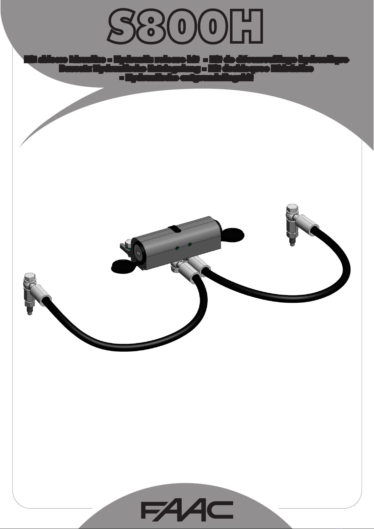
KIT DE DÉVERROUILLAGE HYDRAULIQUE / BAUSATZ HYDRAULISCHE ENTRIEGELUNG S800H
FRANÇAIS
1. BESCHREIBUNG DER BAUTEILE
Die Beschreibung der Entriegelungsbauteile bezieht sich auf die Fig. 1
2. MONTAGEANWEISUNGEN
Diese Anweisungen gelten für die Montage des hydraulischen
Entriegelungssystems am Antrieb S800H und dienen als Ergänzung für die
Anleitungen zur Montage des Antriebs, die im entsprechenden Handbuch
enthalten sind.
Die Maße für die Positionierung des Kastens müssen den Werten in Fig.
2 entsprechen.
• Die Automation entriegeln
• Die Komponenten des Bausatzes genutete Verbindung gemäß
den Angaben in Fig. 3 und Fig. 4 positionieren und dabei auf die
MarkierungandergenutetenVerbindungachten.DasU-Prolander
genuteten Verbindung verschweißen (siehe Fig. 4).
• Die Montage gemäß den Angaben in den Anweisungen für den
Antrieb S800H vornehmen und dabei besonders dessen Position im
Kasten beachten.
• Den Körper der Entriegelungsvorrichtung an die Ölleitungen
anschließen (siehe Abb. 5). Den Vorgang für beide Leitungen
wiederholen.
• Den Hydraulikkreis gemäß den Angaben in Abschn. 3 entlüften.
• Das Entriegelungssystem mithilfe der zwei im Lieferumfang
enthaltenenSchraubenM8xieren(Abb.6,Bez.a)
• Den Antrieb montieren und das Entriegelungssystem mithilfe der zwei
imLieferumfangenthaltenenSchraubenM8xieren(Fig.6,Bez.a)
• Die am Antrieb montierten Entlüftungsverbindungen entfernen
und anschließend die mit dem Entriegelungssystem gelieferten
anschließen (Fig. 6, Bez. bund Fig. 1, Bez. von ebis i), und mit
einem Anzugsmoment von maximal 20 Nm anschrauben (Verbindung/
Kontermutter nicht komplett am Flansch festziehen). Nach der
Befestigung der Verschraubung die Kontermutter festziehen (Bez.
Abb. 7).
• Die Ölleitung mit den zwei Dichtungen und dem Anschlussstück
anschließen (dabei die in Abb. 1, Bez. ebis i, und Abb. 7
angegebene Reihenfolge beachten.)
• Den Antrieb erneut verriegeln.
3. ENTLÜFTEN DER AUTOMATION
Luft im Hydrauliksystem verursacht Betriebsstörungen der Automation,
die unregelmäßige Flügelbewegungen und übermäßigen Betriebslärm
zur Folge haben.
UmAbhilfezuschaffen,sindfolgendeSchritteauszuführen:
1) Einen Befehl für die Öffnung des Tors senden.
2) Während der Flügelbewegung die Entlüftungsschraube beim Öffnen
lockern (Fig. 8, Bez. a).
3) Über die Entlüftungsschraube solange Luft aus dem Hydrauliksystem
ablassen, bis nicht emulgiertes Öl austritt.
4) Die Entlüftungsschraube festziehen, bevor der Antrieb den
Öffnungsvorgang abgeschlossen hat.
5) Einen Befehl zum Schließen des Tors senden.
6) Während der Flügelbewegung die Entlüftungsschraube beim
Schließen lockern (Fig. 8, Bez. b).
7) Über die Entlüftungsschraube solange Luft aus dem Hydrauliksystem
ablassen, bis nicht emulgiertes Öl austritt.
8) Die Entlüftungsschraube festziehen, bevor der Antrieb den
Schließvorgang abgeschlossen hat.
9) Die Vorgänge gegebenenfalls wiederholen.
10) Öl nachfüllen (das im Lieferumfang des Bausatzes enthaltene Öl
verwenden) – Füllstand knapp unter dem Stopfen (Fig. 9, Bez.a).
4. VERWENDUNG DES ENTRIEGELUNGSSYSTEMS
Zum Entriegeln des Antriebs die Kunststoffabdeckung abnehmen,
den Schlüssel einstecken und das Entriegelungsschloss gegen
den Uhrzeigersinn ungefähr einmal vollständig drehen. (Fig. 10
Bez. a)
Zum erneuten Verriegeln des Antriebs das Entriegelungsschloss im
Uhrzeigersinn bis zumAnschlag drehen und dabei keine Gewalt
anwenden (Fig. 10, Bez. b)
5. VERWENDUNG DER BOHRSCHABLONE
Für die Verwendung der Bohrschablone bei nicht mit
Befestigungsbohrungen ausgestatteten Gehäusen wird auf Abb. 11
verwiesen.
a Visdexationdusystème
bVis de purge
cSerrure de déverrouillage
(a/b)
dCache-vis de purge
eVisdexationduraccord
fJoints d’étanchéité
gTube de connexion
h Raccord
i Contre-écrou de serrage
jRécipient d’huile
k Gabarit de perçage
2. PROCÉDURE D’INSTALLATION
La présente procédure se réfère à l’installation du système de
déverrouillage hydraulique sur l’opérateur S800H ; il s’agit d’une
intégrationdelaséquenced’installationdel’opérateur,gurantdans
le manuel correspondant.
Les dimensions relatives au positionnement du boîtier doivent
correspondre à celles de la Fig. 2.
• Déverrouiller l’automatisme.
• Positionner les éléments du kit joint rainuré d’après la Fig. 3 et la Fig.
4, en respectant le positionnement de la référence sur le joint rainuré ;
souderleprolenUsurcedernierd’aprèslaFig.4
• Procéder à l’installation en suivant les instructions de l’opérateur
S800H, en particulier pour ce qui concerne le positionnement de
ce dernier à l’intérieur du boîtier
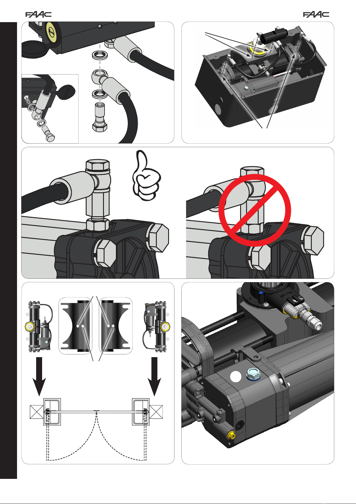
• Assembler le corps du dispositif de déverrouillage aux tubes de
connexion de l’huile, d’après la Fig. 5. Répéter l’opération pour
les deux tubes..
• Effectuer l’opération de purge du circuit hydraulique d’après les
instructions fournies au paragraphe 3.
• Fixer le système de déverrouillage par l’intermédiaire des deux
vis M8 fournies (Fig. 6 réf. a)
• Aprèsavoirinstallél’opérateur,xerlesystèmededéverrouillage
avec les deux vis M8 fournies (Fig. 6 réf. a)
• Démonter les raccords de purge installés sur l’opérateur puis
connecter les raccords fournis avec le système de déverrouillage
(Fig. 6 réf. bet Fig. 1 réf. de eà i), en les vissant à un couple
de serrage maximal de 20Nm et sans serrer complètement le
grouperaccord/contre-écrousurlabride.Unefoisqueleraccord
estxé,serrerlecontre-écrou(réf.Fig.7).
• Raccorder le tube de l’huile muni des deux joints et du raccord
(en suivant l’ordre indiqué dans la Fig. 1, rif. de eà iet Fig. 7)
• Bloquer de nouveau l’opérateur.
3. PURGE DE L’AUTOMATISME
La présence d’air dans le circuit hydraulique provoque un fonctionnement
irrégulier de l’automatisme ; celui-ci se manifeste par un mouvement
anormal du vantail et un bruit excessif durant le fonctionnement.
Pour remédier au problème, procéder comme suit :
1) Commander l’ouverture du portail.
2) Durant le mouvement du vantail, desserrer la vis de purge d’ouverture
(Fig. 8 réf. a)
3) Laisser s’échapper à travers la vis de purge l’air en provenance du
circuit hydraulique jusqu’à la présence de l’huile émulsionnée.
4) Serrer la vis de purge avant que l’opérateur ne termine le cycle
d’ouverture.
5) Commander la fermeture du portail.
6) Durant le mouvement du vantail, desserrer la vis de purge de
fermeture (Fig. 8 réf.b)
7) Laisser s’échapper à travers la vis de purge l’air en provenance du
circuit hydraulique jusqu’à la présence de l’huile émulsionnée.
8) Serrer la vis de purge avant que l’opérateur ne termine le cycle de
fermeture.
9) Répéter les opérations en cas de besoin.
10) Rétablir le niveau d’huile, en utilisant l’huile fournie, de manière à ce
que le niveau se situe immédiatement sous le bouchon (Fig. 9 réf.a).
4. UTILISATION DU SYSTÈME DE DÉVERROUILLAGE
Pour déverrouiller l’opérateur, enlever la protection en plastique,
introduire la clé et tourner la serrure de déverrouillage d’environ un
tour en sens inverse horaire. (Fig. 10 réf. a)
Pour bloquer de nouveau l’opérateur, tourner la serrure de
déverrouillage en sens horaire jusqu’à la butée, sans forcer davantage
(Fig. 10 réf. b)
5. UTILISATION DU GABARIT DE PERÇAGE
Pour l’utilisation du gabarit de perçage, sur des boîtiers dépourvus
detrousdexation,voirlag.11
a Befestigungsschrauben
bEntlüftungsschrauben
c Entriegelungsschloss (a/b)
dAbdeckung
Entlüftungsschrauben
eBefestigungsschrauben
Verbindungsstück
f Dichtungen
g Anschlussrohr
h Verbindungsstück
i Kontermutter zur
Befestigung
j Ölbehälter
k Bohrschablone
DEUTSCH
4
KIT DESBLOQUEO HIDRÁULICO S800H / HYDRAULISCHE ONTGRENDELINGSKIT S800H
ESPAÑOL
1. DESCRIPCIÓN DE LOS COMPONENTES
La descripción de los componentes del desbloqueo hace referencia
a la Fig. 1
a Tornillosdejación
b Tornillos de purga
c Cerradura de desbloqueo (a/b)
d Tapa de los tornillos de purga
e Tornillosdejaciónracor
f Juntas de estanqueidad
g Tubo de conexión
h Racor
i Contratuerca de apriete
j Recipiente de aceite
kPlantilla de taladrado
2. PROCEDIMIENTO DE INSTALACIÓN
Las presentes instrucciones describen la instalación del sistema de
desbloqueo hidráulico en el operador S800H, y deben considerarse una
integración de las instrucciones para la instalación del operador incluidas
en el correspondiente manual.
Las medidas para la colocación de la caja deben coincidir con las indicadas
en la Fig. 2.
• Desbloquee el automatismo.
• Coloque los componentes del kit junta acanalada como se indica en la
Fig. 3 y en la Fig. 4, prestando atención a respetar el posicionamiento
delareferenciasituadaenlajuntaacanalada.SueldeelperlenU
a la junta acanalada como se muestra en la Fig. 4.
• Proceda con la instalación siguiendo las instrucciones del operador
S800H, y en especial la parte dedicada al posicionamiento del mismo
dentro de la caja.
• Ensamble el cuerpo del desbloqueo con los tubos de conexión del
aceite, tal y como se indica en la Fig. 5. Repita la operación para
ambos tubos.
• Purgue el circuito hidráulico siguiendo las indicaciones del párrafo 3.
• Fije el sistema de desbloqueo por medio de los dos tornillos M8
suministrados (Fig. 6 ref. a)
• Unavezinstaladoeloperador,jeelsistemadedesbloqueoconlos
dos tornillos M8 suministrados en dotación (Fig. 6 ref. a)
• Retire los racores de purga instalados en el operador y seguidamente
conecte los racores suministrados con el sistema de desbloqueo
(Fig. 6 ref. by Fig. 1 ref. de ea i), , atornillándolos con un par de
apriete máximo de 20Nm y sin apretar completamente el conjunto
racor/contratuerca en la brida. Una vez jado el racor, apriete la
contratuerca (ref. Fig. 7).
• Conecte el tubo de aceite provisto de las dos juntas y del racor
(siguiendo el orden indicado en la Fig. 1, ref. de ea iy Fig. 7).
• Bloquee de nuevo el operador.
3. PURGADO DEL AUTOMATISMO
La presencia de aire en el circuito hidráulico ocasiona un funcionamiento
irregular del automatismo, que se maniesta con un movimiento
anómalo de la hoja y un excesivo ruido durante el funcionamiento.
Para obviar el problema proceda del siguiente modo:
1) Mande la apertura de la cancela.
2) Durante el movimiento de la hoja, aoje el tornillo de purga de
apertura (Fig. 8 ref.a)
3) Por medio del tornillo de purga haga salir el aire del circuito hidráulico,
hasta que salga aceite no emulsionado.
4) Apriete el tornillo de purga antes de que el operador termine el ciclo
de apertura.
5) Mande el cierre de la cancela.
6)Duranteelmovimientodelahoja,aojeeltornillodepurgadecierre
(Fig. 8 ref.b).
7) Por medio del tornillo de purga haga salir el aire del circuito hidráulico,
hasta que salga aceite no emulsionado.
8) Apriete el tornillo de purga antes de que el operador termine el ciclo
de cierre.
9) Repita las operaciones si fuera necesario.
10) Reponga el nivel de aceite, utilizando el suministrado en el kit,
de modo que el mismo esté justo por debajo del tapón (Fig. 9 ref.a).
4. USO DEL SISTEMA DE DESBLOQUEO
Para desbloquear el operador retire la protección de plástico,
introduzca la llave y gire aproximadamente una vuelta
en sentido antihorario la cerradura de desbloqueo. (Fig. 10
ref. a).
Para volver a bloquear el operador gire la cerradura de
desbloqueo en sentido horario hasta el tope, sin forzarla (Fig. 10
ref. b)
5. PLANTILLA DE TALADRADO
Para el uso de la plantilla de taladrado en cajas no provistas de
oriciosdejación,consultelaFig.11
1. BESCHRIJVING VAN DE ONDERDELEN
De beschrijving van de onderdelen van de ontgrendeling betreft Fig. 1
2. INSTALLATIEPROCEDURE
Deze procedure betreft de installatie van het hydraulische
ontgrendelingssysteem op de aandrijving S800H, en vormt een
aanvulling op de installatieprocedure van de aandrijving die is
aangegeven in de bijbehorende handleiding.
De afmetingen voor het plaatsen van de behuizing moeten
overeenkomen met die in Fig. 2.
• Automatisch systeem ontgrendelen
• Plaats de onderdelen van de kit met groefverbinding zoals
aangegeven in Fig. 3 en Fig. 4 met inachtneming van de markering
opdegroefverbinding;lashetU-proelaandegroefverbinding
zoals geïllustreerd in Fig. 4
• Vervolg de installatie volgens de instructies van de aandrijving
S800H, met name die over hoe zij in de behuizing moet worden
geplaatst.
• Assembleer de behuizing van de ontgrendeling met de
verbindingsleidingen voor de olie zoals aangegeven in Fig. 5.
Herhaal deze handeling bij beide leidingen.
• Ontlucht het hydraulisch circuit zoals aangegeven in paragraaf 3.
• Bevestig het ontgrendelingsmechanisme met behulp van de twee
bijgeleverde schroeven M8 (Fig. 6 ref. a)
• Installeer de aandrijving, bevestig het ontgrendelingssysteem met
de twee bijgeleverde schroeven M8 (Fig. 6 ref. a).
• Verwijder de ontluchtingsaansluitingen die op de aandrijving zijn
geïnstalleerd, en sluit de bij het ontgrendelingssysteem geleverde
aan (Fig. 6 ref.ben Fig. 1 ref.etot i), en draai ze vast met een
koppel van maximaal 20Nm, en draai in ieder geval het geheel
aansluiting-vergrendelingsmoerop deensniet helemaalvast.
Draai als de aansluiting is bevestigd de vergrendelingsmoer vast
(ref. Fig. 7).
• Sluit de olieleiding samen met de pakkingen en de aansluiting aan
volgens de volgorde in Fig. 1, ref. etot ien Fig. 7
• Vergrendel de aandrijving weer.
3. ONTLUCHTING VAN HET AUTOMATISCH SYSTEEM
Als er lucht in het hydraulische circuit zit, werkt het automatisch systeem
niet goed, met als gevolg dat de vleugel schokkerig beweegt en veel
lawaai maakt tijdens de werking.
Handel als volgt om dit probleem te verhelpen:
1) Geef het commando voor het openen van de poort.
2) Draai terwijl de vleugel in beweging is de ontluchtingsplug voor het
openen los (Fig. 8 ref.a)
3) Laat de lucht via de ontluchtingsplug uit het hydraulische circuit
ontsnappen tot er niet-geëmulgeerde olie verschijnt.
4) Draai de ontluchtingsplug vast voordat de aandrijving de
openingscyclus heeft beëindigd.
5) Geef het commando voor het sluiten van de poort.
6) Draai terwijl de vleugel in beweging is de ontluchtingsplug voor het
sluiten los (Fig. 8 ref.b)
7) Laat de lucht via de ontluchtingsplug uit het hydraulische circuit
ontsnappen tot er niet-geëmulgeerde olie verschijnt.
8) Draai de ontluchtingsplug vast voordat de aandrijving de
sluitingscyclus heeft beëindigd.
9) Herhaal deze handeling indien nodig.
10) Herstel het oliepeil door de bij de kit verstrekte olie bij te vullen tot
het peil vlak onder de dop komt (Fig. 9 ref.a).
4. GEBRUIK VAN DE ONTGRENDELINGSSYSTEEM
Om de aandrijving te ontgrendelen moet de kunststof bescherming
worden verwijderd, steek dan de sleutel in het slot en draai hem ongeveer
een slag tegen de wijzers van de klok in. (Fig. 10 ref.a).
Om de aandrijving weer te vergrendelen moet de sleutel met de wijzers
van de klok mee worden gedraaid tot hij niet verder kan, zonder hem
te forceren (Fig. 10 ref. b)
5. GEBRUIK VAN DE SJABLOON MET GATEN
Voor het gebruik van de sjabloon met gaten op behuizingen zonder
bevestigingsgaten, zie Fig. 11
a Bevestigingsschroeven
b Ontluchtingsplug
c Slot ontgrendeling (a/b)
d Dop ontluchtingsplug
e Bevestigingsschroeven
aansluiting
f Dichting
g Verbindingsleiding
h Aansluiting
i Vergrendelingsmoer
j Oliereservoir
kSjabloon voor het boren
NEDERLANDS
a
bc ac b
d
Fig. 1
e
f
g
h
Fig. 2
57
A
A = 45 mm
= =
Fig. 3 Fig. 4
Raccolta immagini - Pictures collection - Collection de Figures -
Conjunto de imágenes - Abbildungen - Fotoverzameling
j k
i
NEDERLANDS ESPAÑOL DEUTSCH FRANÇAIS ENGLISH ITALIANO
Fig. 5 b
a
Fig. 6
a
b
a
Fig. 7
Fig. 8
NEDERLANDS ESPAÑOL DEUTSCH FRANÇAIS ENGLISH ITALIANO
Fig. 9
< 20 Nm
NEDERLANDS ESPAÑOL DEUTSCH FRANÇAIS ENGLISH ITALIANO
bFig. 10
a
b
c
dØ 6,5mm
e
M8
a
f
Fig. 11
SEDE - HEADQUARTERS
FAAC S.p.A.
Via Calari, 10
40069 Zola Predosa (BO) - ITALY
Tel. +39 051 61724 - Fax +39 051 758518
www.faac.it - www.faacgroup.com
ASSISTENZA IN ITALIA
SEDE
tel. +39 051 6172501
www.faac.it/ita/assistenza
MILANO
tel +39 02 66011163
[email protected]
PADOVA
tel +39 049 8700541
[email protected]
ROMA
tel +39 06 41206137
[email protected]
TORINO
tel +39 011 6813997
[email protected]
FIRENZE
tel. +39 055 301194
[email protected]
SUBSIDIARIES
AUSTRIA
FAAC GMBH
Salzburg, Austria
tel. +43 662 8533950
www.faac.at
FAACTUBULARMOTORS
tel. +49 30 56796645
[email protected]
www.faac.at
GERMANY
FAAC GMBH
Freilassing, Germany
tel. +49 8654 49810
www.faac.de
FAACTUBULARMOTORS
tel. +49 30 5679 6645
[email protected]
www.faac.de
BENELUX
FAACBENELUXNV/SA
Brugge, Belgium
tel. +32 50 320202
www.faacbenelux.com
FAACTUBULARMOTORS
Schaapweg 30
NL-6063 BA Vlodrop, Netherlands
tel. +31 475 406014
[email protected]
www.faacbenelux.com
AUSTRALIA
FAACAUSTRALIAPTYLTD
Homebush – Sydney, Australia
tel. +61 2 87565644
www.faac.com.au
INDIA
FAAC INDIA PVT. LTD
Noida – Delhi, India
tel. +91 120 3934100/4199
www.faacindia.com
SWITZERLAND
FAAC AG
Altdorf, Switzerland
tel. +41 41 8713440
www.faac.ch
CHINA
FAAC SHANGHAI
Shanghai, China
tel. +86 21 68182970
www.faacgroup.cn
NORDIC REGIONS
FAAC NORDIC AB
Perstorp, Sweden
tel. +46 435 779500
www.faac.se
POLAND
FAAC POLSKA SP.ZO.O
Warszawa, Poland
tel. +48 22 8141422
www.faac.pl
UNITED KINGDOM
FAACUKLTD.
Basingstoke-Hampshire,UK
tel. +44 1256 318100
www.faac.co.uk
SPAIN
F.A.A.C. SA
San Sebastián de los Reyes.
Madrid, Spain
tel. +34 91 6613112
www.faac.es
RUSSIA
FaacRUSSIA
Moscow, Russia
www.faac.ru
FRANCE
FAAC FRANCE
Saint Priest - Lyon, France
tel. +33 4 72218700
www.faac.fr
FAAC FRANCE - AGENCE PARIS
Massy - Paris, France
tel. +33 1 69191620
www.faac.fr
FAAC FRANCE - DEPARTEMENT VOLETS
Saint Denis de Pile - Bordeaux, France
tel. +33 5 57551890
fax +33 5 57742970
www.faac.fr
U.S.A.
FAAC INTERNATIONAL INC
Jacksonville,FL-U.S.A.
tel. +1 904 4488952
www.faacusa.com
FAAC INTERNATIONAL INC
Fullerton,California-U.S.A.
tel. +1 714 446 9800
www.faacusa.com
MIDDLE EAST
FAAC MIDDLE EAST BRANCH
DubaiAirportFreeZone-Dubai,UAE
tel. +971 42146733
www.faac.ae
732957 - Rev. D

Other manuals for S800H

1

Other FAAC DC Drive manuals

FAAC T-MODE TM R E Series User manual

FAAC

FAAC T-MODE TM R E Series User manual

Popular DC Drive manuals by other brands

ABB ACS480 Troubleshooting

ABB

ABB ACS480 Troubleshooting

Danfoss VLT series operating instructions

Danfoss

Danfoss VLT series operating instructions

Siemens SINAMICS PERFECT HARMONY GH180 Function manual

Siemens

Siemens SINAMICS PERFECT HARMONY GH180 Function manual

LS Industrial Systems SV-iV5 Series user manual

LS Industrial Systems

LS Industrial Systems SV-iV5 Series user manual

Parker P Series user guide

Parker

Parker P Series user guide

DALCNET DLB1248 Series Device manual

DALCNET

DALCNET DLB1248 Series Device manual

Welcon WEC-D048/25-FS0025-E Hardware manual

Welcon

Welcon WEC-D048/25-FS0025-E Hardware manual

Orbitalum RPG 1.0 Operating instructions with spare parts list

Orbitalum

Orbitalum RPG 1.0 Operating instructions with spare parts list

Boston gear Right 90 Series Installation and operation manual

Boston gear

Boston gear Right 90 Series Installation and operation manual

easydriver basic 1.8 Installation and instruction manual

easydriver

easydriver basic 1.8 Installation and instruction manual

Siemens 3TL60 operating instructions

Siemens

Siemens 3TL60 operating instructions

Power Electronics SD700 Series Hardware and installation manual

Power Electronics

Power Electronics SD700 Series Hardware and installation manual

Raymarine E12026 installation guide

Raymarine

Raymarine E12026 installation guide

LSIS SV-iS7 series manual

LSIS

LSIS SV-iS7 series manual

Inovance MD800 Series quick start guide

Inovance

Inovance MD800 Series quick start guide

Becker Extended Features XR7/85 Assembly and operating instructions

Becker

Becker Extended Features XR7/85 Assembly and operating instructions

Danfoss VLT HVAC Drive FC 102 Programming guide

Danfoss

Danfoss VLT HVAC Drive FC 102 Programming guide

Technosoft iMOTIONCUBE BX-CAN Technical reference

Technosoft

Technosoft iMOTIONCUBE BX-CAN Technical reference

manuals.online logo
manuals.online logoBrands
  • About & Mission
  • Contact us
  • Privacy Policy
  • Terms and Conditions

Copyright 2025 Manuals.Online. All Rights Reserved.