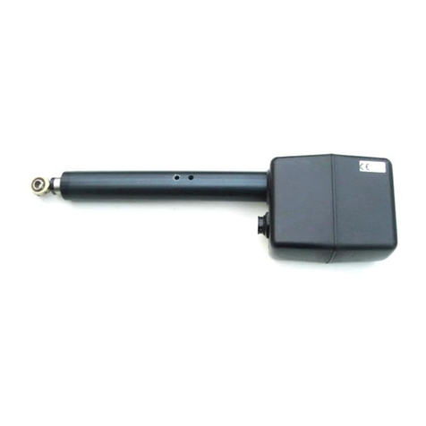
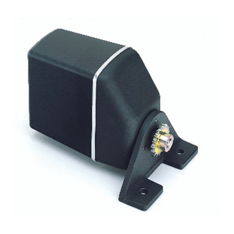
Raymarine E12026 User manual

Distributed by
Any reference to Raytheon or
RTN in this manual should be
interpreted as Raymarine.
The names Raytheon and RTN
are owned by the
Raytheon Company.
All manuals and user guides at all-guides.com
all-guides.com

Universal
I/O Drive
Installation Guide
Drives covered:
E12026 Universal I/O (Stern) Drive 12 V
Document number: 81180-3
March 2001
All manuals and user guides at all-guides.com

2 Universal I/O Drive - Installation Guide
Important information
Safety notices
WARNING: Product installation
Thisequipmentmustbeinstalledandoperated inaccordance
withtheinstructionscontainedinthishandbook.Failuretodoso
couldresultinpoorproductperformance,personalinjuryand/
ordamagetoyourboat.
Because correctperformance of the boat’s steering is critical for
safety,weSTRONGLYRECOMMENDthatanAuthorized
RaymarineServiceRepresentativefits thisproduct.
WARNING: Navigation aid
Althoughwehavedesignedthisproducttobe accurateand
reliable, many factorscan affectits performance. Asaresult,it
shouldonlybeused asanaidtonavigationandshouldnever
replacecommonsenseandnavigationaljudgement.Always
maintaina permanentwatchsoyoucanrespondtosituationsas
theydevelop.
EMC conformance
All Raymarine equipment and accessoriesare designed tothe best
industry standards for use in the recreational marine environment.
The design and manufacture of Raymarine equipmentand
accessories conformto theappropriate Electromagnetic
Compatibility(EMC)standards,butcorrectinstallationisrequiredto
ensure that performance isnot compromised.
Handbook information
To the best ofour knowledge, the information in this handbook was
correct when it went to press. However, Raymarine cannot accept
liabilityforanyinaccuraciesoromissionsitmaycontain.Inaddition,
ourpolicy ofcontinuousproduct improvement may change
specifications without notice. As a result, Raymarine cannot accept
liabilityfor any differences between the product and thehandbook.
©RaymarineLtd2001.
All manuals and user guides at all-guides.com

Universal I/O Drive - Installation Guide 3
Introduction
Product description
Welcometotheinstallation guidefortheRaymarineuniversal
inboard/outboarddrive(also known as anI/Oor sterndrive).This
productis intended to operate the boat’s steering mechanism as part
of a Raymarine autopilot system.
CAUTION:
This drive isonly designed to drive cable operated, power
assistedsteeringsystems.AnyattempttoinstallanI/Odriveto a
non-compatibleenginetypemayvoidthe warrantyon boththe
driveand the engine.
The drive operates the power steering valve inthe same way as the
steeringcable. Whenyoudisengage the autopilot, a clutch
disengagesthe I/Odriveso you cansteerthe boatmanually.
Figure 1: Main parts of the universal I/O drive
Contents
Thisguide contains:
1Product specifications page 4
2Installation instructions page 5
3Maintenance information page 14
D5210-1
Girdle tube Rod end
Socket
for cable
Push rod
Drive cable
Main motor, gear
and clutch assembly
All manuals and user guides at all-guides.com

4 Universal I/O Drive - Installation Guide
Specifications
Drive specifications
Drive dimensions
Figure 2: Universal I/O drive dimensions
Table 1: Drive specifications
Performance
(at nominal voltage)
Universal I/O drive
E12026 (12 V)
Drive method Electromechanical
Maximum thrust 50 kg (110 lb)
Maximum stroke 214 mm (8.3 in)
Hardover to hardover time 8.8 sec
Other information
protected for use in engine compartments
CE approvals - conforms to:
89/336/EC (EMC), EN60945:1997
94/25/EC (RCD), EN28846:1993
103 mm
(4 in)
62 mm
(2.4 in)
911 mm
(35.8 in)
1115mm
(43.8 in)
354 - 568 mm
(13.9 - 22.3 in)
D5186-1
All manuals and user guides at all-guides.com

Universal I/O Drive - Installation Guide 5
Installation instructions
Parts required
To install the I/O drive the following parts are supplied:
•universalI/O driveunit
•power cable
•adaptorpinsfor Mercruiser and Volvoengines
•hexagonalbracket, securingbolts (x2), lock washers(x2)
•fixing clamps (x2),self-tapping screws (x2) and tie-wraps (x2)
Installation steps
WARNING: Electrical safety
Makesureyouhaveswitchedoffthepowersupplybeforeyou
startinstallingthisproduct.
Follow these steps to install your I/O drive unit:
Ï
Ï
Ï
1. EMC installation guidelines
All Raymarine equipment andaccessories are designedto the best
industrystandards for use in the recreational marine environment.
Their design and manufacture conforms to the appropriate
Electromagnetic Compatibility (EMC) standards, but correct
installation is required to ensure that performance is not
compromised. Although every effort has been taken to ensure that
1Consult the EMC installation guidelines. page 5
2Mount the drive. page 7
3Connect the power cable. page 12
4Complete the post-installation checks. page 13
All manuals and user guides at all-guides.com
all-guides.com

6 Universal I/O Drive - Installation Guide
they willperform under allconditions, itis important to understand
whatfactorscould affectthe operationofthe product.
TheguidelinesgivenheredescribetheconditionsforoptimumEMC
performance, butit is recognized that it may notbe possible to meet
all of these conditions in all situations. To ensure the best possible
conditionsforEMC performancewithin the constraints imposedby
any location, always ensure the maximum separation possible
between different items of electrical equipment.
For optimumEMC performance, it isrecommended that wherever
possible:
•Raymarine equipment and cables connectedto it are:
•At least3 ft (1 m) from any equipment transmittingor cables
carryingradiosignalse.g.VHF radios,cablesand antennas.
In the case of SSB radios, the distance should be increased to
7ft(2m).
•More than7 ft (2m) from the path ofa radar beam. Aradar
beam can normally be assumed to spread 20degrees above
andbelow theradiatingelement.
•The equipment is supplied from a separate battery fromthat used
for engine start. Voltage drops below10 V, and startermotor
transients,cancausetheequipmenttoreset.Thiswillnotdamage
theequipment,butmay cause theloss ofsome informationand
maychange theoperatingmode.
•Raymarine specified cables are used. Cutting and rejoining these
cables can compromise EMC performanceand must be avoided
unless doing sois detailed in the installation manual.
•Ifasuppressionferriteisattachedtoacable,thisferriteshouldnot
beremoved.Iftheferrite needs to be removed duringinstallation
it mustbe reassembled in the sameposition.
Suppression ferrites
Figure 3showstypicalcable suppressionferritesusedwith
Raymarine equipment. Use the ferritessuppliedby Raymarine.
Connections to other equipment
If your Raymarine equipment is to be connected to otherequipment
usingacablenotsuppliedbyRaymarine,asuppressionferriteMUST
always be attached tothe cable nearto theRaymarine unit.

All manuals and user guides at all-guides.com

Universal I/O Drive - Installation Guide 7
Figure 3: Typical Suppression Ferrites
2. Mounting the drive
CAUTION:
I/Odrivesareaffectedbysubstantialvibrationduringuse.When
installingthisI/Odrive,makesurethatyoufullytightenallbolts
anduselockwashers.Usingasuitablethread-lockingcompound
onthethreadswillhelpkeepthe boltssecurelytightened.
1. Select thecorrect adaptor pinforyour engine type.
2. Removethelocatingpinthatattachesthe steeringcable rodtothe
tillerblock.
3. Replaceitwiththeadaptorpinsupplied,usingthesplitpintohold
itin place (seefollowingfigures).
D3548-2
Volvo Mercruiser
D4599-2
All manuals and user guides at all-guides.com

8 Universal I/O Drive - Installation Guide
D4532-2A
Adaptor pin
Steering cable rod
Tiller block
Fitting Volvo adaptor pin
Aft
D4532-2B
Adaptor pin
Steering cable rod Tiller block
Fitting Mercruiser adaptor pin
Aft
All manuals and user guides at all-guides.com

Universal I/O Drive - Installation Guide 9
4. Fit the supplied hexagonal bracket centrally onthe existing
steering cable securing nut (see following figures). Securethe
bracket withoneof the securing boltsandlockwashers supplied,
ensuring that it is correctly aligned with the adaptor pin.
D4587-3A
Hexagonal
bracket
Ensure adaptor pin and
hexagonal bracket are in line
Fitting hexagonal clamp to Volvo
Aft
D4587-3B
Ensure adaptor pin and
hexagonal bracket are in line
Hexagonal
bracket
Fitting hexagonal clamp to Mercruiser
Aft
All manuals and user guides at all-guides.com

10 Universal I/O Drive - Installation Guide
5. Insert the metal cable end of the I/O drive into the clamp on the
hexagonal bracket:
•makesurethegrooveonthecableendfitsontotheridgeinside
theclamp
•secure the clamp with the remaining securing bolt and lock
washer
6. Extendthe I/O drive cableuntil the rod endis aligned withthe
adaptorpin, then:
•fit the rodend ontothe adaptor pin
•secure the rod end with the split pin supplied (see following
figures)
D4534-3A
Rod end
Fitting cable to Volvo
Aft
All manuals and user guides at all-guides.com
all-guides.com

Universal I/O Drive - Installation Guide 11
7. Usetheclampsandtie-wrapssuppliedtomountthemainbodyof
the I/O drive in a suitable, safe position, remote from the engine.
CAUTION:
Youcan bend thedrivecablewhenmountingtheI/Odrive,but
the bend radius must always be more than 100 mm (4 in).
D4534-3B
Rod end
Fitting cable to Mercruiser
Aft
D4535-1
All manuals and user guides at all-guides.com

12 Universal I/O Drive - Installation Guide
8. Completea hardover to hardover check:
•Slowlyturn the steeringsystem fromhardover tohardover.
•Makesurethatthesteeringsystemoperatesfreelyandthatthe
drive unit and drive cable make nocontactwith anypart of
theengineor boat.
Mounting in a restricted area
If an obstruction prevents youfrom installing the universal I/O drive
unit as supplied, rotate the girdle tube relative to the drive cable:
1. Loosenthe grub-screws at theend of the girdle tube
2. Rotate the drive cable as required.
3. Remove the grub-screws one at a time, put thread-locking
compound on the thread, then replace and tighten the grub-screw.
4. Completeanother hardover to hardovercheck.
3. Electrical connections
WARNING: Electrical safety
Makesurethepowersupplyisswitchedoffbeforeyoumakeany
electrical connections.
Whenyou have fitted theI/Odrive tothe steeringsystem,connectit
to the course computer asfollows:
1. Plug inthe power cable (supplied) into the socket on the drive
unit. Lock the connector in place by turning the lockingring
clockwise.
2. Route the cable to the course computer, taking into account the
EMC installation guidelines (see page 5).
3. Connectthemotorcables(thickerblueandbrowncables)andthe
clutch cables (thinnerred and blackcables) to theconnections on
the course computer asshown in Figure 4.
4. Secure the cable close to the I/O drive unit, making sure there is
enough free length to allow the drive unit to move.
5. Completeanotherhardovercheck:usethesteeringwheeltomove
the rudder from hardover to hardover, andcheck that the cable
doesnotcatch onanypart of theboat or itsfittings.
All manuals and user guides at all-guides.com

Universal I/O Drive - Installation Guide 13
Figure 4: Connections at course computer
4. Post-installation check
WARNING:
Keepclearofmovingsteeringsystemsat alltimes.Protect
movingpartsfromaccessduringnormaluse.
WARNING:
Only operate the autopilot system with theengines running and
power-assistedsteeringoperating.
Check the following points after installing the drive:
1. Is thedrive unit securely attached to the steering system (with all
brackets, bolts, split pins, etc. secure)?
2. Is the drive unit correctly aligned?
3. Are the motor andclutch cables correctly routed and securely
connected to thecourse computer?
4. Completea hand-steeringcheck:Areyousure thereisnocontact
betweenthedriveunitandanypartof theengine,steeringsystem
orboat’sstructurewhen the pushrod movesin andout?
Note:When you have installed the entire autopilot system, you will
needtocompleteanautopilotsteeringcheck.Refertothecontrolunit
handbookfor more details.
D5184-2
lk CLUTCH MOTORPOWER
+–+–12
MOTORPOWER
+– AB
OFF
SWITCH SOLENOID
–
CLUTCH
+
––
Type 100/300 course computerType 150/400 course computer
red
brown
blue
black red
black
brown
blue
All manuals and user guides at all-guides.com

14 Universal I/O Drive - Installation Guide
Maintenance
Ona regular basis:
•check all connectionsand mountings are secure
•checkdrive alignment
•check cables for signs of wear or damage
EMC servicing and safety guidelines
•Raymarineequipmentshouldbe servicedonly byauthorized
Raymarine service technicians. They will ensure that service
procedures and replacement parts used will not affect
performance. There are no user serviceable partsin any
Raymarineproduct.
•Some productsgenerate high voltages, so never handle the
cables/connectors when poweris being supplied to the
equipment.
•When powered up,all electrical equipment produces
electromagnetic fields. These can causeadjacent piecesof
electrical equipment to interact with one another, with a
consequent adverse effect on operation. In orderto minimize
these effects and enable you toget the best possible performance
fromyour Raymarine equipment, guidelines aregiven in the
installationinstructions,to enableyouto ensure minimum
interaction between different items ofequipment, i.e. ensure
optimum Electromagnetic Compatibility (EMC).
•Alwaysreport anyEMC-related problemto your nearest
Raymarine dealer. We use such information to improve our
qualitystandards.
•In someinstallations, it may notbe possible toprevent the
equipmentfrombeingaffectedbyexternalinfluences.Ingeneral
this will not damage the equipment but it can lead to spurious
resetting action, ormomentarily may result in faulty operation.
All manuals and user guides at all-guides.com

Universal I/O Drive - Installation Guide 15
Product support
Raymarine products are supported by a worldwide networkof
distributors and AuthorizedService Representatives.
If youencounter any difficulties with this product, pleasecontact
eitheryournationaldistributor, or your service representative,or the
RaymarineTechnicalServicesCallCenter.Refertothebackcover
or the WorldwideDistributor List for contact details.
All manuals and user guides at all-guides.com
all-guides.com

16 Universal I/O Drive - Installation Guide
Raymarine Ltd
Anchorage Park
Portsmouth, Hampshire
England PO3 5TD
Telephone +44 (0)23 9269 3611
Fax +44 (0)23 9269 4642
www.raymarine.com
Raymarine Inc
22 Cotton Road, Suite 280
Nashua
NH 03063-4219, USA
Telephone +1 603 881 5200
Fax +1 603 864 4756
www.raymarine.com
Raymarine Technical Services Call Center
UK: +44 (0)23 9271 4713 or
+44 (0)23 9269 3611 ext. 1083
USA: +1 603 881 5200 or
1-800-539-5539 ext. 2333
All manuals and user guides at all-guides.com
Table of contents
Other Raymarine DC Drive manuals

Raymarine
Raymarine M81135 User manual

Raymarine
Raymarine Universal IO Drive User manual

Raymarine
Raymarine Hydraulic Linear Drive User manual

Raymarine
Raymarine IO Drive User manual

Raymarine
Raymarine SmartPilot X-10 User manual

Raymarine
Raymarine Mk II User manual

Raymarine
Raymarine M81138 User manual

Raymarine
Raymarine M81138 User manual

Raymarine
Raymarine M81135 User manual