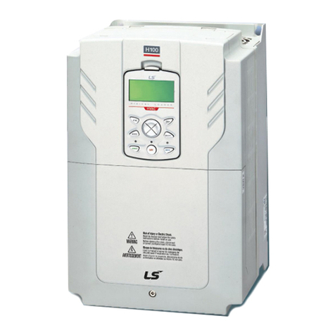
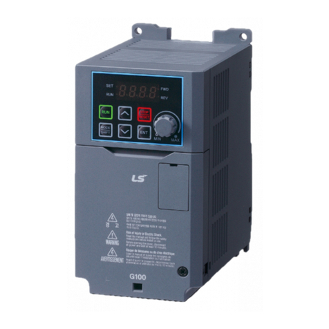
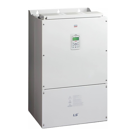
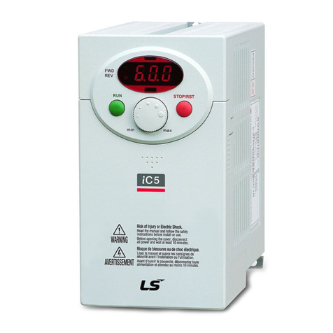
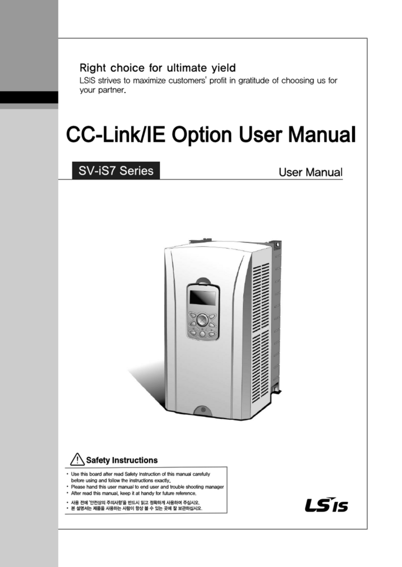
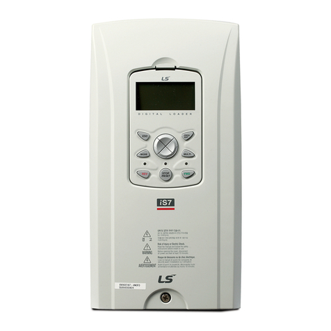
LSIS SV-iS7 series User manual

1
Safety Information
Read and follow all safety instructions in this manual precisely to avoid unsafe operating
conditions, property damage, personal injury, or death.
Safety symbols in this manual
Indicates an imminently hazardous situation which, if not avoided, will result in severe injury or
death.
Indicates a potentially hazardous situation which, if not avoided, could result in injury or death.
Indicates a potentially hazardous situation that, if not avoided, could result in minor injury or
property damage.
Safety information
•
Do not open the cover of the equipment while it is on or operating. Likewise, do not operate
the inverter while the cover is open. xposure of high voltage terminals or charging area to
the external environment may result in an electric shock. Do not remove any covers or
touch the internal circuit boards (PCBs) or electrical contacts on the product when the
power is on or during operation. Doing so may result in serious injury, death, or serious
property damage.
•
Do not open the cover of the equipment even when the power supply to the inverter has
been turned off unless it is necessary for maintenance or regular inspection. Opening the
cover may result in an electric shock even when the power supply is off.
•
The equipment may hold charge long after the power supply has been turned off. Use a
multi-meter to make sure that there is no voltage before working on the inverter, motor or
motor cable.
•
Supply earthing system: TT, TN, not suitable for corner-earthed systems

2
•
This equipment must be grounded for safe and proper operation.
•
Do not supply power to a faulty inverter. If you find that the inverter is faulty, disconnect the
power supply and have the inverter professionally repaired.
•
The inverter becomes hot during operation. Avoid touching the inverter until it has cooled to
avoid burns.
•
Do not allow foreign objects, such as screws, metal chips, debris, water, or oil to get inside
the inverter. Allowing foreign objects inside the inverter may cause the inverter to
malfunction or result in a fire.
•
Do not operate the inverter with wet hands. Doing so may result in electric shock.
•
Do not modify the interior workings of the inverter. Doing so will void the warranty.
•
The inverter is designed for 3-phase motor operation. Do not use the inverter to operate a
single phase motor.
•
Do not place heavy objects on top of electric cables. Doing so may damage the cable and
result in an electric shock.

3
Table of Contents
1
Introduction ............................................................................................................................... 5
1.1
Purpose of the Manual .............................................................................................................................. 5
1.2
Intended Use ................................................................................................................................................... 5
1.3
Intended Audience ....................................................................................................................................... 6
1.4
Product Identification .................................................................................................................................. 6
1.5
Part Names....................................................................................................................................................... 8
1.6
Block Diagram ............................................................................................................................................. 10
2
Installation Instruction .......................................................................................................... 11
2.1
Installation Considerations ................................................................................................................... 11
2.2
Selecting and Preparing a Site for Installation.......................................................................... 12
2.3
Mounting.......................................................................................................................................................... 15
2.4
Motor Connection ...................................................................................................................................... 18
2.5
AC Input Connection ................................................................................................................................ 22
2.6
Grounding ....................................................................................................................................................... 24
2.7
Control Wiring .............................................................................................................................................. 28
3
Start-Up Procedure ................................................................................................................ 36
3.1
Safety Instructions for Start-Up.......................................................................................................... 36
3.2
About the Keypad ...................................................................................................................................... 37
3.2.1
Operation Keys......................................................................................................................... 38
3.2.3
Display Modes .......................................................................................................................... 42
3.2.4
Mode shift .................................................................................................................................... 45
3.2.5
Group shift ................................................................................................................................... 47
3.2.6
Code(Function Item) shift ................................................................................................... 50
3.2.7
Parameter setting .................................................................................................................... 54
3.2.8
Operating status monitoring ............................................................................................. 56
3.2.9
Failure status monitoring .................................................................................................... 59
3.2.10
How to initialize parameters.............................................................................................. 62
3.3
asy Start ....................................................................................................................................................... 63
3.4
Trial Run .......................................................................................................................................................... 66
4
3.5
Application Set-up xamples.............................................................................................................. 67
3.5.1
Terminal Block as a Command Input Device (Fwd/Rev run commands)
.......................................................................................................................................................... 67
3.5.2
Setting a Frequency Reference using Input Voltage(V1) ............................... 68
3.5.3
Setting a Reference Frequency using Input Current (I1) ................................ 69
3.5.4
Setting a Frequency Reference via RS-485 Communication ...................... 70
4
Diagnostics and Troubleshooting ..................................................................................... 71
4.1
Trip and Warning ........................................................................................................................................ 71
4.1.1
Fault Trips .................................................................................................................................... 71
4.1.2
Warning Message ................................................................................................................... 75
4.2
Troubleshooting Fault Trips ................................................................................................................. 76
4.3
Troubleshooting Other Faults ............................................................................................................. 79
4.4
Troubleshooting Flow Chart ................................................................................................................ 84
4.5
How to Check Power Components ................................................................................................ 90
5
Technical Specification ........................................................................................................ 92
5.1
Input and Output Specifications ........................................................................................................ 92
5.2
Cable Selection ........................................................................................................................................... 97
5.3
Product Specification Details ........................................................................................................... 100
5.4
Terminal Screw Specifications ........................................................................................................ 103
5.5
xternal Dimensions (UL nclosed Type1, IP21 Type) ................................................... 105
5.6
xternal dimension (UL nclosed Type12, IP54 Type) ................................................... 119
5.7
Peripheral Devices ................................................................................................................................. 123
5.8
Reactors, Braking Resistor and Fuse Specifications ........................................................ 125
5.9
Braking Resistor and Fuse Specifications ............................................................................... 127
6
arranty ................................................................................................................................. 129
7
Appendix ................................................................................................................................ 131

5
1 Introduction
1.1
Purpose of the Manual
This instruction manual provides information for safe installation, and commissioning of the
SV-IS7 Series..
Read and follow the instruction manual in order to use the IS7 drive safely and
professionally, and pay particular attention to the safety instructions and general warnings.
Keep this instruction manual available with the IS7 drive at all times.
Note
Detailed informations for each parameter is on technical manual.
1.2
Intended Use
The inverter is an electronic motor controller that :
1. Regulates motor speed in response to system feedback or to remote commands from
external controllers. A power drive system consists of the IS7 inverter, the motor and
equipment driven by the motor.
2. Monitors aspects of system and motor status.
3. Can be used for motor protection.
Depending on configuration, the inverter can be used in standalone applications or form
part of a larger appliance or installation.
The inverter is intended for use in residential, industrial and commercial environments in
accordance with local laws and standards. Do not use the inverter in applications that do
not comply with specified designated operating conditions and environments.

6
1.3
Intended Audience
This start-up manual is for:
• Knowledge of standard electrical wiring practices, electronic components,and electrical
schematic symbols.
• Minimal knowledge of SV-IS7 product names and terminology.
• No experience or training in installing, operating, or servicing SV-IS7.
The audience for this manual will install, start-up, and service SV-IS7.
1.4
Product Identification
The SV-IS7 Inverter is manufactured in a range of product groups based on drive capacity
and power source specifications. Product name and specifications are detailed on the rating
plate. Check the rating plate before installing the product and make sure that the product
meets your requirements. For more detailed product specifications.
Note
Check the product name, open the packaging, and then confirm that the product is free from
defects. Contact your supplier if you have any issues or questions about your product.

7

8
1.5
Part Names
The illustration below displays part names. Details may vary between product groups.
0.75~75k (3-Phase)
Front cover
Remove it
when wiring
Keypad
Wiring
b
racket
Cooling FAN
Ground
t
erminal
Volt for
f
ront cover
to
fix
Keypad
connection
ncoder option
Wiring bracket
Communication
Option connection
PLC, xtention I/O,
Communication
Option connection
I/O board and terminal
Power terminal

9
90~375k (3-Phase)
Keypad
Volt for upper front
cover(left side)
Volt for lower front
cover(left side)
Lower front cover
Power input
Upper front cover
Volt for upper front
cover(right)
Volt for lower front
cover(right)
Signal input
Ground
SCR Snubber
Communication
Option
ncoder Option
Keypad
connection
I/O board and terminal
Power Busbar(R/S/T,
U/V/W, P/N)
FAN SMPS
circuit
MAIN SMPS
circuit
PLC, xtention
I/O etc option
Sh
ie
ld plate

10
1.6
Block Diagram
No.
Name
Description
1 Line power input
3-phase AC line power supply to the
adjustable frequency drive
2 Rectifier The rectifier bridge converts the AC input
to DC current to supply inverter power
3 P1(+), P2(+) DC reactor wiring connection.
4 Charging
resistor
Restrict inrush current when power is
turned on.
5 Capacitor Bank Stores the DC power.
6 Dynamic
Braking Unit
In above ranges (30~375kW), Braking unit
has to be additionally installed.
7 Inverter
Converts the DC into a controlled PWM
AC waveform for a controlled variable
output
to the motor.
8 Output to motor Regulated 3-phase output power to the
motor

11
2 Installation Instruction
2.1
Installation Considerations
Inverters are composed of various precision, electronic devices, and therefore the
installation environment can significantly impact the lifespan and reliability of the
product. The table below details the ideal operation and installation conditions for
the inverter.
Items
Description
Ambient Temperature*
- CT (Heavy Duty) load : - 10 ~ 50
℃
(without ice or frost)
- VT (Normal Duty) load : - 10~ 40
℃
(without ice or frost)
(It is recommended that you use less than 80% load when you use
VT load at 50
℃
.)
- IP54 product: -10~40
℃
(without ice or frost)
Ambient Humidity 90% relative humidity (no condensation)
Storage Temperature - 4–149
°
F (-20–65
℃
)
nvironmental Factors An environment free from corrosive or flammable gases, oil residue
or dust
Altitude/Vibration Lower than 3,280 ft (1,000 m) above sea level/less than 0.6 G (5.9
m/sec2)
Air Pressure 70 –106 kPa
* The ambient temperature is the temperature measured at a point 2” (5 cm) from the
surface of the inverter.

12
2.2
Selecting and Preparing a Site for Installation
Be careful so that the plastic parts of the inverter may not be damaged.
Do not move the product holding the cover only.
Do not install the product where there is vibration, a press or cart..
Life of the inverter greatly influenced by the surrounding temperatures, make sure that the
surrounding temperature does not exceed the permitted temperature (-10 ~ 50 C).
The life of the inverter is affected by ambient temperature. Place that inverter installed in of
ambient temperatures should not exceed the following allowable temperature.
When the inverter is installed inside the panel, panel temperature must not exceed the
following allowable temperature. In other word, the ambient temperature inside or outside of
the panel, regardless of the installation, needs a 5cm gap around the inverter as shown.
<Measurement Points of Surrounding Temperature>
Allowable Temperature
Characteristics, such as no ice in
ambient Temperature
CT(Heavy Duty) load: - 10 ~ 50
℃
VT(Normal Duty)load: - 10~ 40
℃
(However, VT(Normal Duty) in 50
℃
,
less than 80% of the load use
recommended)
IP54 Product : -10 ~40
℃

13
Install the inverter on an inflammable surface because its temperature rises high during
operation.
Sufficient space is required to prevent heat saturation because the inverter emits heat.

14
Remark
Over 50cm, B : over 20cm is necessary when you install an inverter above 30kW
If you install two or more inverters inside the panel, be careful about the location of the
ventilation fan and inverter. See the figure below.
Install the inverter upright using screws or bolts so that the inverter does not move.
Note
Arrange the panels in order to the hot air generated by the heating of the inverter should be
released.
Caution
Avoid direct rays of light or a warm and humid place.
Install the inverter in a closed panel or clean place free from foreign substances such as
oil mist and fiber dust.
In order to meet the MC standard, 200V 30~75kW and more than 90kW product
should be installed inside a metal cabinet or panel.
Acceptable(O) Acceptable(X) Acceptable(O) Acceptable(X)
Ventilation Ventilation

15
2.3
Mounting
Mount the inverter on a wall or inside a panel following the procedures provided below.
Before installation, ensure that there is sufficient space to meet the clearance specifications,
and that there are no obstacles impeding the cooling fan’s air flow.
1
Use a level to draw a horizontal line on the mounting surface, and then carefully mark
the fixing points.
2
Drill the two upper mounting bolt holes, and then install the mounting bolts. Do not fully
tighten the bolts at this time. Fully tighten the mounting bolts after the inverter has been
mounted.
3
Mount the inverter on the wall or inside a panel using the two upper bolts, and then fully
tighten the upper mounting bolts.

16
4
Install the two lower mounting bolts. nsure that the inverter is placed flat on the
mounting surface, and that the installation surface can securely support the weight of
the inverter.
Note
The quantity and dimensions of the mounting brackets vary based on frame size.

17
•
Do not transport the inverter by lifting with the inverter’s covers or plastic surfaces. The
inverter may tip over if covers break, causing injuries or damage to the product. Always
support the inverter using the metal frames when moving it.
•
Hi-capacity inverters are very heavy and bulky. Use an appropriate transport method that is
suitable for the weight.
•
Do not install the inverter on the floor or mount it sideways against a wall. The inverter must
be installed vertically, on a wall or inside a panel, with its rear flat on the mounting surface.

18
2.4
Motor Connection
Connect motor by following procedure. Check cable specifications on 5.2 before connecting
.
1
First, separate the keypad and the cable of keypad(❶)
x) 0.75~7.5kW
2
Loosen the bolt that secures the top cover. Then remove the cover by lifting it. (❷)
3
Connect the cables to the power terminals.
❶
❷

19
<Standard type>
<Conduit type>
•
Apply rated torques to the terminal screws. Loose screws may cause short circuits and
malfunctions. Tightening the screw too much may damage the terminals and cause short
circuits and malfuctions.
•
Use copper wires only with 600 V, 75
℃
rating for the power terminal wiring, and 300 V,

20
75
℃
rating for the control terminal wiring.
•
Power supply wirings must be connected to the R, S, and T terminals. Connecting them to
the U, V, W terminals causes internal damages to the inverter. Motor should be connected
to the U, V, and W Terminals. Arrangement of the phase sequence is not necessary.
Other manuals for SV-iS7 series
8
This manual suits for next models
13
Table of contents
Other LSIS DC Drive manuals

LSIS
LSIS S100 Series User manual

LSIS
LSIS Starvert iG5A Series User manual

LSIS
LSIS LSLV-H100 User manual

LSIS
LSIS S100 Series User manual

LSIS
LSIS 004iC5-1 User manual

LSIS
LSIS G100 User guide

LSIS
LSIS H100 User manual

LSIS
LSIS iS7 Series Use and care manual

LSIS
LSIS S100 Series User manual

LSIS
LSIS SV-iS7 series User manual