10 E56-6001-000
02/16/2018
formed are based on the fan setting. If the fan setting is changed on the device
at a later date the pipe system must be re-verified.
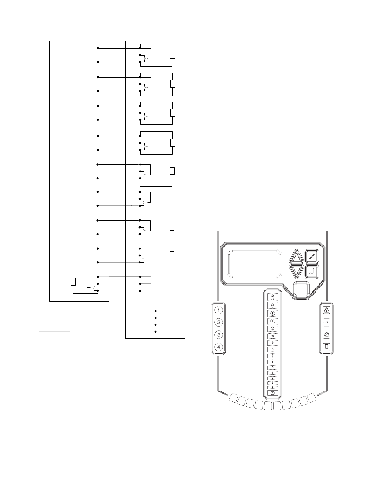
ALARM AND RELAY CONFIGURATION
Alarm thresholds are set to default levels when shipped, but are configurable.
Each Alarm level has its own set of form C relay contacts. As the particulate
level crosses the threshold for the alarm level the corresponding indicator will
illuminate and the relay will activate. The Alarm thresholds and their associ-
ated relay outputs are configurable for latching or non-latching operation For
each alarm level, there is a configurable delay from 0 to 60 seconds. Configu-
rable thresholds for each alarm level are as follows:
TABLE 5. PROGRAMMABLE ALARM LEVELS
ALARM
LEVEL
DEFAULT
THRESHOLD
%OBS/M
PROG.
RANGE
%OBS/M
Alert 0.0396 0.0015 - 20.0
Action1 0.165 0.0015 - 20.0
Action2 0.33 0.0015 - 20.0
Fire1 0.825 0.0015 - 20.0
Fire2 1.65 0.0015 - 20.0
AUDIBLE INDICATOR CONFIGURATION
There is a built audible indicator on the FAAST XT which gives the option to
include a supplementary audible indication of alarms and faults. The settings
are configurable using the PipeIQ software. The sounder is capable of generat-
ing a pulsed or continuous tone. Both the alarm and fault can be selected to
do either tone.
FAILURE OF CONFIGURATION VALIDATION
If configuration validation fails during the configuration process, the software
configuration tool will indicate a failure and the device will illuminate the
fault indicator. Subsequently, the device will not accept any of the data as
valid and will revert back to its previous configuration.
POWER GLITCH DURING CONFIGURATION
During an upload of configuration data, the device will keep the last known
good configuration in memory until a complete validation is done on the new
configuration data. This prevents device corruption in the event of a power
loss or network failure. When power is restored the device will initialize with
the last known good configuration. The device will also indicate a Configura-
tion Fault on the user interface and set the Minor Fault Relay. This will only
occur once. When the next Reset or Power on Reset is performed the device
will continue to use the last known good configuration.
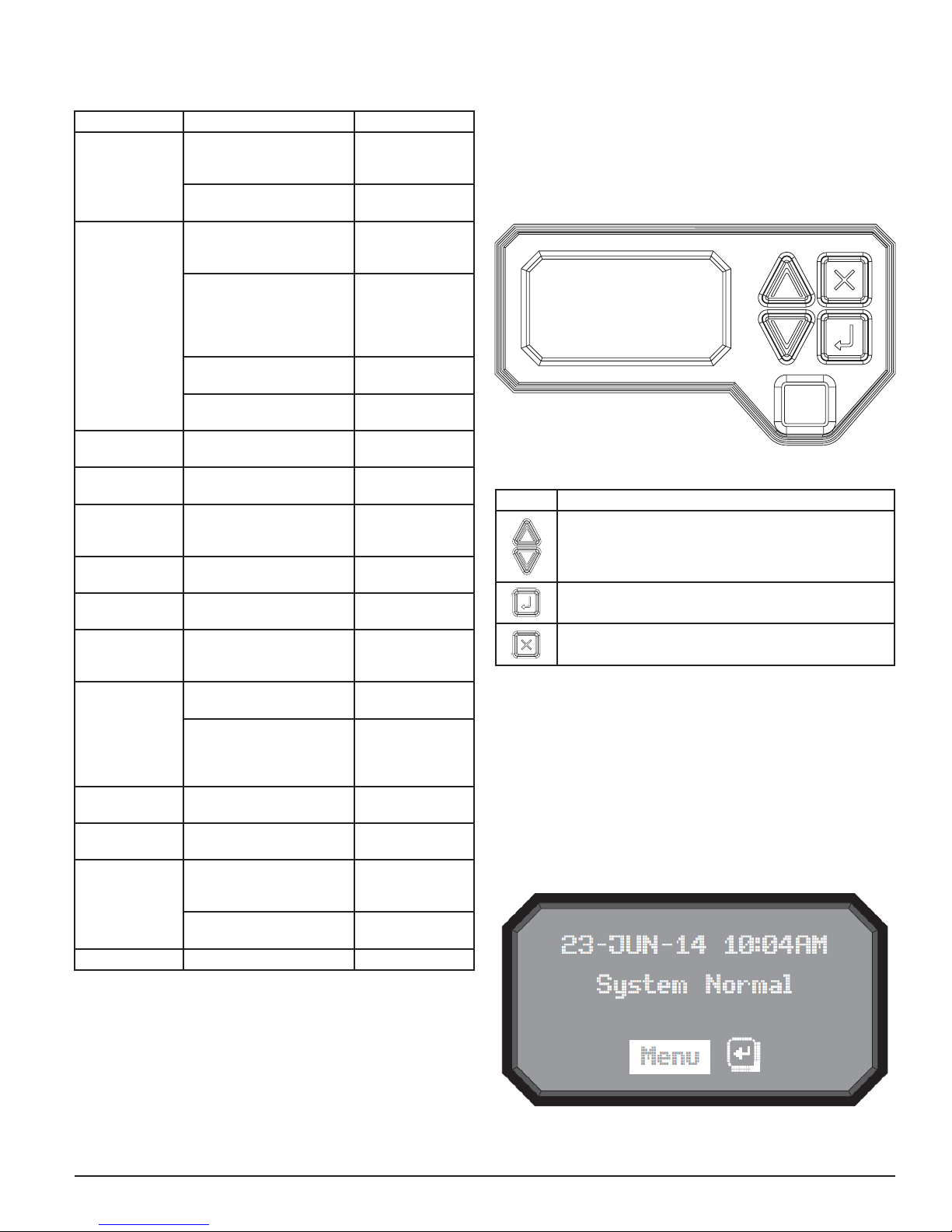
NORMAL
In Normal operating mode the FAAST XT displays the air flow and current
particulate levels on the user display. The time, date, address, and current
obscuration is shown on the LCD. The particulate level is compared to the
threshold levels programmed into the device and will activate the appropri-
ate alarm as the particulate exceeds that threshold. If any fault occurs it will
activate the fault LED and display the type on the LCD as well as set the cor-
responding relay.
TEST
Test mode is initiated through the PipeIQ Live View tab or through the LCD in-
terface. Test mode will simulate a fire condition by activating all ten segments
in the Particulate Level display and each segment in the Alarm display. Each
corresponding alarm relay will also activate after any programmed delay asso-
ciated with that relay. To remove the device from test, a RESET must be done.
SOUNDER TEST
The sounder test function can be accessed via the LCD user interface. Upon
initiation, the device will exercise the selected sounder tones for fault and
alarm conditions. The sounder may be configured to give continuous or pulsed
tones for alarm and fault conditions. Tones may be selected using PipeIQ.
RESET
Reset mode is initiated through the PipeIQ mimic view or through the LCD
interface. When RESET is activated all relays will be reset. It will then enter
Normal mode operation. If any fault or alarm states remain the device will re-
activate the state automatically.
RESET AIRFLOW BASELINES
The airflow baselines can be reset through the LCD screen on FAAST’s user
interface. Selecting this option will cause the FAAST unit to enter in to a five
minute baseline period, which will be displayed on the LCD user interface,
and reset its current air flow baselines.
WARNING
If a high or low condition exists perform a visual inspection of the pipe net-
work to ensure the integrity of the pipe network and that the flow condition is
not caused by breakages or blockages.
ISOLATION
From Normal Mode, Isolation mode is initiated through PipeIQ mimic tab or
through the LCD interface. The device will set the isolation relay and the
isolation fault will be shown on the user interface. The alarm and fault re-
lays will reset and subsequently not change state. In all other respects, the
unit will continue to operate normally. Any smoke exceeding alarm thresholds
will cause alarm conditions to appear on the detector’s front panel, but the
alarm condition will not be communicated to an attached system such as a
fire panel. The device will remain in this mode until it is explicitly removed by
the user, even in the event of power loss or reset.
DISABLE MODE
The user can initiate Disable Mode through the LCD interface only. When
Disable Mode is activated, the device will set the isolation relay and the user
interface will display the disable fault. In Disable Mode, the fan will cease
operation and the particulate, alarm and airflow displays on the user interface
will not be illuminated. The alarm and fault relays will reset and subsequently
not change state. This mode should only be used when the system needs to
be taken offline. This mode is active indefinitely until the user removes the
device from disable mode. All communication interfaces remain active when
the device operates in this state.
ACCLIMATE® MODE
The FAAST system includes an available Acclimate mode. By allowing the de-
vice to operate in Acclimate mode, a device’s susceptibility to nuisance alarms
can be reduced. This provides maximum protection for a device located in
changing environments. The sensitivity of the unit continuously adjusts over
time, within user defined limits, as the environment changes. Acclimate mode
ALARM LEVEL THRESHOLD HIGH
SENSITIVITY
THRESHOLD LOW
SENSITIVITY
CURRENT LEVEL
Alert Alert High Alert Low Acclimate Alert Level
Action 1 Action 1 High Action 1 Low Acclimate Action 1 Level
Action 2 Action 2 High Action 2 Low Acclimate Action 2 Level
Fire 1 Fire 1 High Fire 1 Low Acclimate Fire 1 Level
Fire 2 Fire 2 High Fire 2 Low Acclimate Fire 2 Level
TABLE 6. ACCLIMATE LEVELS