Fabdec DARI-KOOL GALA-KOOL Pro User manual

Page 1
2020A
Part No: GPRO-MAN-V2.5-EN
Installation and Operation Manual
GALA-KOOL Pro Universal Tank Control
Standard version 2.5
REV F

Page 2
Contents
1 Introduction
1.1 Page 4Function overview
2 Safety
2.1 Electrical safety 6 Page
2.2 Intended use 7 Page
2.3 Wiring, screening, earthing Page 7
3 Electrical connection
3.1 Connection diagram 8 Page
4 Technical data
4.1 Technical data of control unit 9 Page
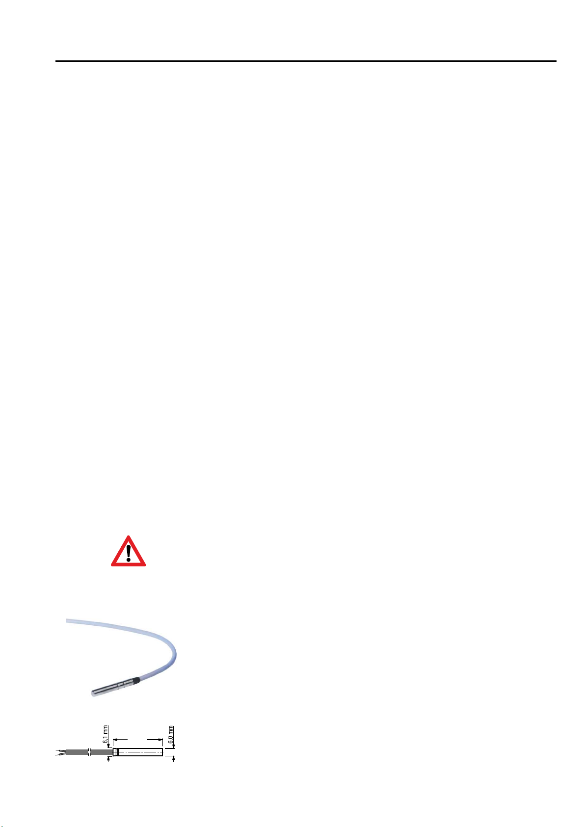
4.2 Fitting the sensor 9 Page
5 Operation
5.1 Setting the date and time 10 Page
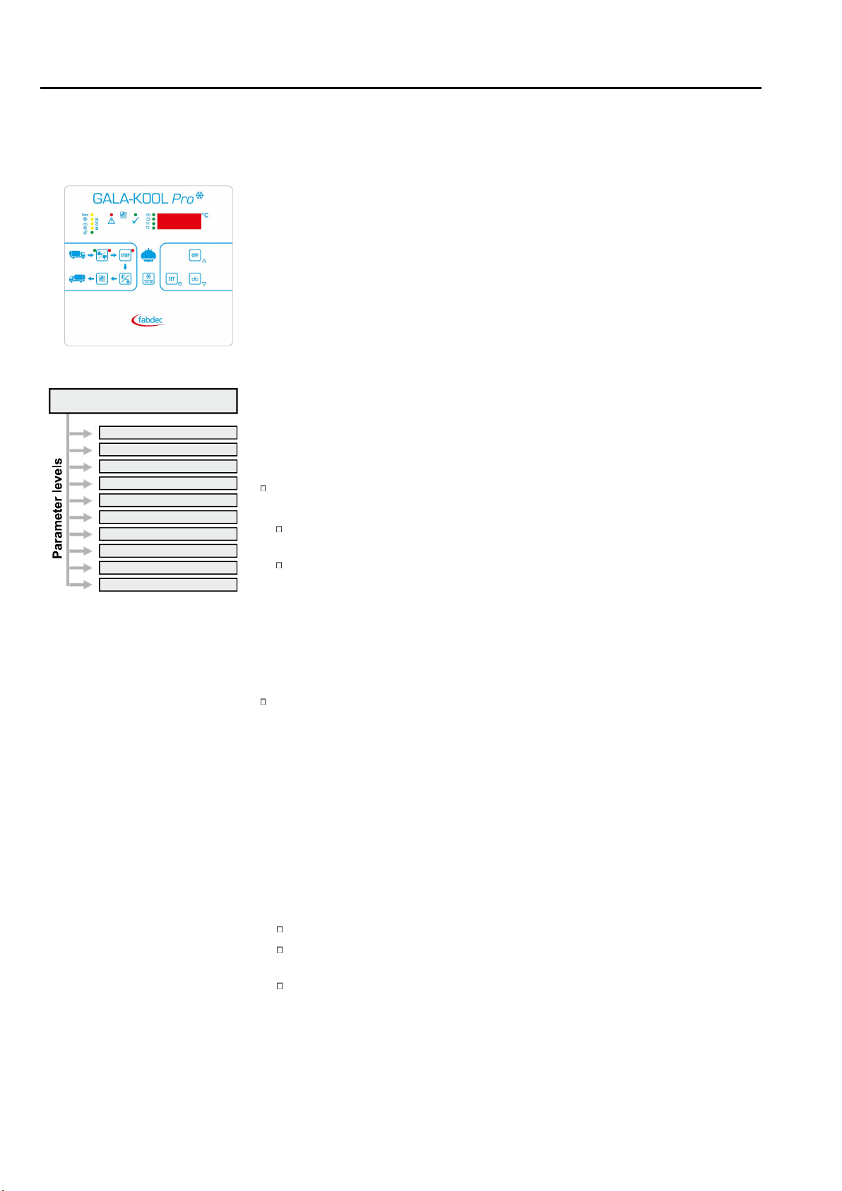
5.2 Operation in levels 11 Page
5. 2.1 Button functions 12 Page
5.2.2 Meaning of the LED’s 13 Page
5. 2.3 Operation modes 14 Page
5. Operation of working level2.4 16 Page
6 Cleaning
6.1 Cleaning methods (cooling tank-configurations) Page 18
6.1.1 Circulation cleaning with a beaker Page 18
6.1.2 Circulation cleaning with two dosing pumps Page 18
6.1.3 Displacement cleaning with feed container, dosing pumps
Page in circulation line 19
6.1.4 Displacement cleaning with feed container dosing pumps and Page 19
6.2 Page 20Cleaning programme diagram
6.3 Page Explanation and programming of the cleaning process 22
6. Page 4 28 Service functions for testing the cleaning cycle
7. Tank monitor and general fault handling
7 Page .1 Description of tank monitor operation 30
7 Page .2 Tank monitor: Milk removal YES or NO 32
7 Page .3 Tank monitor: Handling multiple faults 35
7 Page .4 Tank monitor: Display fault memory 35
7 Listing fault codes and their description Page .5 36
.5.1 Critical tank monitor alarms (red)7 Page 36
.5.2 Informative tank monitor alarms (green)7 Page 37
.5.3 System alarms cleaning7 Page 38
.5.4 System alarms cooling7 Page 40
7. Page 5.5 System alarms external sensors 41
7.5.6 Test alarm Page 41
8. Setting of parameters
8 Page .1 Change and save parameter values 42
8 Level c-parameter Page .2 „General cooling parameters“ 44
8 Level P-parameter Page .3 „Extended cooling parameters“ 46
8 Level n-parameter Page .4 „General cleaning parameters“ 51
8 Level „ r-parameter Page .5 Extended cleaning parameters“ 54
8 Level E-parameter Page .6 „Service parameters“ 59
8 Level h-parameter Page .7 „General tank monitor parameters“ 60
8 Level H-parameter Page .8 „Extended tank monitor parameters“ 62
8 Level -> Event assignment F-parameter Page .9 „Alarm “ 64
8 Level A-parameter Page .10 „ “Configuration 66
8 Level o-parameter Page .11 „I-/O- test parameters“ 72

Page 3
Contents
9. Other information
9 Page .1 Butterfly valve (manual or pneumatic) 74
.2 Safety switch for manual butterfly valve9 Page 75
9 Page .3 Robot control 76
9 Page .3.1 Cleaning release by robot 77
9 Page .4 Different variants for cooling start delay 78
.5 Compressor switch-on delay / pre-agitating9 Page 80
9 Page .6 Emergency cooling / sensor failure 80
9 Sensor correction procedure Page .7 80
.8 Function second temperature sensor9 Page 81
9 Page .9 during coolingLevel alarm 81
9 Page .10 Automatic / convenience functions 81
.11 Heating control9 Page 82
9 Page .12 Function of pressure switch – Effect on pump and heater 82
.13 Air in the cleaning pump -> automatic 9 venting Page 83
9 Page .14 Level control setting 84
.15 Detergent injection position 9 Page 85
.16 Configuration of the different stages9 Page cleaning 85
9.17 Setting of a break in the cleaning programme Page 86
9.18 Page 86Function test alarm
9.19 Activation delay tank monitor Page 87
. Procedure following power failure 889 20 Page
9 21 Power Page . pack (optional) 88
9 22 Page . Agitator monitoring module (optional) 89
9.2 Page 3 90General measures when using electronic control systems

Page 4
1. Introduction
Gala-Kool Pro is a universal tank control unit which combines all the
basic functions in one device:
- milk cooling control
- comprehensive cleaning control
i- an extended robot nterface
- an extended tank monitor
All basic functions can be selected and operated from the working
level. The control unit can also be adapted to a wide range of different
system types and sizes. This takes place through the thematically
organised parameter levels.
1.1 Function overview
Within the working level the control unit differentiates between various operating
modes:
OFF mode (stand-by)
Shows the current time
All LEDs are out
(Exceptions: outlet valve and tank monitor LEDs may be lit)
All output relays are deactivated
) (Exceptions: outlet valve and tank monitor alarms may be active
The other operating modes can only be selected from OFF mode. It is not
possible to switch directly between the different modes.
CAUTION: The control unit is live even when switched off.
Cooling mode
Two freely definable target temperatures can be selected by pressing a button.
If the milk temperature exceeds the selected target temperature (T1 or T2) by
the hysteresis value, the compressor contactor and agitator are switched on
automatically. Once the target temperature is attained, the compressor
contactor switches off, while the agitator continues to run for the set “after-
stirring“ period.
During cooling breaks the agitator switches on periodically, in accordance with
the set 'pause time', in order to ensure an even temperature throughout the milk.
Independently of this, during cooling, short or long “intermediate stirring” can be
switched on by pressing a button.
Cooling can be triggered in different ways:
manually using the “START COOLING“ button
via digital input “Remote start to cooling“
(by robot or external button)
automatically following cleaning (only in conjunction with robot)
Cooling now starts in accordance with the pre-set starting mode:
Immediately or after a cooling start delay, with periodic cooling boosts, etc.
Working level
for normal daily operation
General cooling parameters
Extended cooling parameters
General cleaning parameters
Extended cleaning parameters
Service parameter
General tank monitor parameter
Extended tank monitor parameter
Alarm configuration
Configuration
I/O test parameter

Page 5
Continuous stirring mode
From OFF mode, the agitator can be switched on by pressing a button and then
switched off again by pressing the OFF button.
Parameter [C25] can be used to set the time after which the agitator is to switch
off automatically.
The countdown can be interrupted at any time using the OFF button.
If [C25] is set to '0', the agitator will run continuously, but can be switched off at
any time using the OFF button.
Cleaning mode
The cleaning timer controls the water intake by time or level, as desired. All
running times (heater, pump, detergent injection) can be set separately. The
automatic switchover from acidic to alkaline detergent is also adjustable.
The controls the different processes and times fully automati-Gala-Kool Pro
cally.
Following a power failure the control unit will restart in the mode it was in
Robot interface
Depending on the parameter settings, the control unit includes a built-in robot inter-
face with the following functions:
- „Robot start / stop“ and
- “Butterfly valve open / closed“
These functions are controlled via the keypad.
Tank monitor function
During the entire cooling and cleaning process, the built-in tank monitor keeps check
on the correct operation of all components, in order to guarantee the perfect state of
the milk.
In particular, the following are monitored:
- minimum and maximum milk temperatures during cooling
- power failure (optionally power pack required!)
- agitator function (optionally agitator monitoring module required
- minimum and maximum temperatures during cleaning
- etc.
Any faults are indicated by two LEDs, and associated f codes flash in the display.ault
In the case of errors which may jeopardise the milk quality, the red LED “Don't add
milk” lights up.
1. Introduction

Page 6
The controller itself and the associated control circuits and load circuits must be pro-
tected separately and in accordance with the local regulations.
The separate protection of the control- and load circuit must be carried out according
to local conditions!
In order to prevent destruction of the relay or semiconductor relay outputs in the event
of a short-circuit, the load circuit should be fused to the maximum permissible output
current.
As well as incorrect installation, wrong parameter settings can also adversely affect
the correct functioning of the controller. For this reason, safety devices that are inde-
pendent of the controller should always be used, e.g. high and low pressure valves
or temperature limiters. Account should be taken of the local safety regulations in
this connection.
The load circuit (relay outputs K1 to K1 ) must be fused in accordance with the con-3
nected components.
The connection of external voltages to the digital inputs can lead to the destruction of
the control.
Caution: All cables to the digital inputs must be shielded and kept as short as possi-
ble. EMC.
Important note concerning the external fuse
The transformer, which is installed in the , has a two-chamber safety Gala-Kool Pro
winding, which is only short-circuit-proof due to the built-in thermal protection. If the
temperature exceeds 145 ° C, there is a risk of damage!
Protect control unit with an external fuse of 160mA!
2. Safety
2.1 Electrical safety

Universal tank controllers are designed to control systems, con-Gala-Kool Pro wash
densing units, alarms etc. in milk cooling tanks as well as to monitor milk quality. Fur-
thermore, connected milking robots can be controlled. Any other use of the device is
permitted only with prior written permission from the manufacturer.
The controller is intended only for incorporating into machinery, display panels or
switchboxes etc. and when fitted correspond to protection class 2 (double or rein-ing
forced insulation) It is only allowed to be put into operation in installed state. The use .
of the control is permitted in devices of protection class 1 and 2. The controller must
not be modified or converted in any way.
The controller is ready for use only when the parameters have been set universal tank
appropriately. Its use before this has been done would have no benefits and could also
damage the equipment or adversely affect the m to be temperature-controlled.ilk
Responsibility for the faultless functioning of the connected devices lies with the plant
engineer or the installer or the service engineer who has installed and commissioned
the .Gala-Kool Pro
The device is fitted with a resistance temperature sensor.
The controller is not suitable for use in explosive atmospheres. Danger of explosion.
Use only outside areas subject to explosive atmospheres.
The fulfils the EC requirements for electromagnetic compatibility Gala-Kool Pro
(EMC) and the Low Voltage Directive (LVD).
The safety components meet the VDE regulations.
2. Safety
2.2 Intended use
These operating instructions contain important technical and safety
information. Please read carefully before installation and before any
work on or with the regulator.
Page 7
Wherever possible, keep input, output and supply leads and sensor cable physically
separate from each other and do not lay them parallel to each other.
Mains voltage cables and low-voltage cables must not be laid in one cable.
Use screened and twisted interface and sensor cables.
Earth the screening of temperature sensors unilaterally in the switchbox.
Ensure correctly wired potential equalisation.
When selecting wiring materials and installing and connecting the temperature control-
ler to the electricity supply, account must be taken of DIN VDE 0100 “Erection of power
installations with rated voltages below 1000” or the relevant national regulations (e.g.
based on IEC 60364).
2.3 Wiring, screening, earthing

Page 8
3.1 Connection diagram
Default configuration
3. Electrical connection
Electrical connections must be as shown in the diagram below.
Use cable bushes.
Make sure that cables cannot chafe.
Observe relay current rating.
In all cases use contactors for pump, compressor and heater.
Do not feed digital inputs with external voltage! Use potential-free
The assignment of components to the is set in relay outputs
the A parameters (A1 to A1 ). 3 (See section 8.10)
The assignment of components to the is set in digital inputs
the A parameters (A21 to A28). (See section 8.10)
GND * = capacitively decoupled from GND
If the tank housing is to be used as one of
the two level poles, this pole must be
connected to GND*.
K13
K12
K11 K10 K9 K8 K7 K6 K5 K4 K3 K2 K1
10 9 8 7 6 5 E2 4 3 2 1 E1 E1 NC A1 A2
22 23 24 25 26 27 28 29 30 31
RX/TX-(B)
RX/TX+(A)
RS-485
49 48 47 46
IO-BUS
13 14 15
16 17 18
19 20 21
Tank Monitor - Alarms
Robot Stop
General Alarms
Level 1
Level 2
Temp. Sensor 1
Temp. Sensor 2
KTY81-210
KTY81-210
12V DC EXT.
+
-
B
A
LN
230VAC
50..60HZ
Important note:
Above diagram shows manufacturer default relay configuration. See page 67 for market
specific settings.

4.1 Technical data of control unit
Operating voltage 230V AC +/-10%, 50/60 Hz
Relay contact 1 relays3
max. switching current x A AC1 - 250V AC11 10
x 1 A AC1 - 250V AC2 6
max. switching voltage 250V AC - 50..60 Hz
Display 4 13 mm LED-Display, digits
Display range -999 ... 9999
LED switching status displays 3 mm
Number of sensor inputs 1 or 2
Measurement range -5° ... +95°C
Temperature resolution 0.1°C
Sensor input KTY 81-210
Control mode two-step controller
Hysteresis* 0.1 K .. 99,9 K (standard adjusting 0.7 K)
Water detection via 2 independent level monitors
Target temperature T1* standard adjusting °C4
Target temperature T2* standard adjusting 4°C
Digital inputs 8 (via optocoupler)
Interface 2x RS 485
Connection Plug-in screw connections
for cables up to 2 5 mm².
Environment specifications:
- Operation temperature 0° .. +50°C
- Storage temperature -20° .. +70°C
- max. humidity 75% (no dew)
Technical data subject to change
Page 9
4. Technical Data
4.2 Fitting the sensor
When setting the temperature controller parameters (and whenever the sensor is
replaced) the “actual value correction” [Parameter C91] must be adjusted so that the
temperature measured corresponds to that shown on the display. A reference thermo-
meter should be used for this purpose.
Pay attention to the permitted temperture range for sensor cable exposure.
40 mm
The sensor cable must not be chafed or kinked.
There must be no substantial mechanical pressure on the sensor tube.
Do not place the sensor and the high-voltage cable in the same cable
conduit (not even within the switchbox).
Temperature range sensor cable -10°C .. +70°C
Changing the sensor cable length
lf it is necessary to shorten or lengthen the sensor cable on installation (or if a sensor
other than the one supplied is to be fitted), the "actual value correction" parameter
must be adjusted accordingly.

Page 10
Year
Date
Time
5.1 Setting the date and time
When the power is connected ...
... there are two possible displays:
1.) Time is lost: 4 dashes are shown:
The date and time must be re-entered. Proceed as follows:
Press one of the arrow keys: the year appears, flashing.
Set the time as described below.
2.) Time is still preserved:
During initialisation, 4 rotating bars are shown, then the current firmware
appears briefly, then the time is displayed. If it is not correct, adjust it as
follows.
Setting the time during normal operation
Press OFF button: a time is displayed. the
Hold the SET button down until the year appears, flashing.
(in between, the tank temperature is shown briefly)
Use the arrow keys to set the correct year
Press the SET button: the month appears, flashing.
Use the arrow keys to set the correct month.
Press the SET button: the day appears, flashing.
Use the arrow keys to set the correct day.
Then set the hour and minute displays in the same way.
When finished press the SET button.
actual timeSetting is completed, and the is displayed.
In the event of a power cut, the date and time are retained for up to 5
days. After that they must be re-entered.
5. Operation

5.2 Operation in levels
General cooling parameters - parameter)(c
Parameters such as setpoints, hysteresis etc. can be set here.
Extended cooling parameters - (P parameter)
Setting of plant-specific functions such as agitator function, cooling start variant,
milk removal option, etc.
General cleaning parameters - (n parameter)
Parameters such as the run times of the rinses etc. can be set here.
Extended cleaning parameters - parameter)(r
Setting of plant-specific functions such as configuration of safety elements, level
detection, number of passes of individual etc.cleaning stages
Service parameters - (E parameter)
Displays the tank monitor parameters and counters
General tank monitor parameters - (h-parameter)
Determine whether and when are triggeredinformative alarms
Extended tank monitor parameters - (H parameter)
Determine whether and when are triggeredcritical alarms
Alarm configuration - (F parameter)
Here an individual behaviour can be assigned for each fault.
Configuration - (A parameter)
Determination / Parameterisation of the hardware configuration
I / O test parameters - (o parameter)
Is intended for commissioning the control system.
The working level is used for
operation and control in every-
day operation.
The is Gala-Kool Pro
parameterized in 10 different
parameter levels.
The subordinate parameter
levels are only entered after
entering a code in order to
avoid inadvertent adjust-
ment of the parameters.
General cooling parameters C parameter code: C212
Extended cooling parameters P parameter code: D345
General cleaning parameters n parameter code: B454
Extended cleaning parameters r parameter code: C567
Service parameter s E arameter p code: EA03
General tank monitor parameters h parameter code: 4711
Extended tank monitor parameters H parameter code: F94A
Alarm configuration F parameter code: FFFF
Configuration A parameter code: A384
I/O test parameters o. parameter code: 10E5
Working level
Page 11
5. Operation

„OFF“ button
To change to a different mode, always first press the “OFF” button.
active modes are closed down when the OFF button is pressed.
Switch control unit to STAND-BY
Close down cleaning mode or continuous stirring mode prematurely
Acknowledge error
Change to programming mode (hold down button for 3 seconds)
„SET“ button
in OFF mode = press briefly: Display of critical faults (if available)
Hold down for 3 seconds: set date and time
in cleaning mode = “Cleaning stage” or “Tank temperature” is displayed
(see Parameter [r97])
and current error
Parameter setting = the current value entered is displayed
= Tank monitor the current error code is displayed
“COOL” button
in OFF mode = start cooling
press 2x = bypass the cooling start delay (if set)
press long = new start of the cooling-start-delay
in cooling mode = change target temperature T1 / T2
„AGITATOR” button
in OFF mode = start modecontinuous stirring
in cooling mode = press for 1 second: "Intermediate stirring SHORT"
press for 3 seconds: "Intermediate stirring LONG”
See also section “Cooling mode” at the end of
“WASHING” button
in OFF mode = start cleaning
“ARROW KEYS”
To select and adjust parameters.
5.2.1 Button functions
„RESET“ button
press briefly =Confirmation of the message “do not load”
hold 5 seconds = Test of the red alarm-LED
„ROBOT STOP button“ (if parameterized)
Starts or stops both the robot and the cooling mode as well.
„PNEUMATIC OUTLET VALVE“ button (if parameterized)
Opens / closes the pneumatic outlet valve.
Operation by the driver of the milk truck
Page 12
OFF
SET
T1/T2
OFF
STOP
5. Operation

5.2.2 Meaning of the LED‘s
LED "AGITATOR”
during cooling mode Agitator is switched on
LED "COMPRESSOR“
on Compressor contactor is switched on
off Compressor contactor is switched off
flashing Pause time compressor (pendulum protection)
LED "T1” or „T2"
T1 on Set target temperature for "T1" is active
T2 on Set target temperature for "T2" is active
LED “ERROR”
flashing The control is in error mode and must be
acknowledged with the "OFF" button.
LED “END OF CLEANING / TANK EMPTY”
permanent Cleaning successfully finished -
tank is ready for further filling.
LEDs in cooling mode
LEDs in cleaning mode
T1
T2
T1
T2
T1
T2
!
!
Page 13
Mode
Cooling
Agitation
Washing
Pneumatic outlet valve ON/OFF
5. Operation

Page 14
The current time is displayed.
The control unit is on stand-by
All LEDs are outmode .
All output relays are deactivated
(Exceptions: robot, butterfly valve and tank monitor alarms may be active)
The other operating modes can only be selected from OFF mode. It is not possi-
ble to switch directly between the different modes.
CAUTION: The control unit is live even when switched off.
OFF mode
Cooling mode is started in all cases from the OFF mode.
Starting takes place:
MANU LLY by pressing the COOL buttonA
DIGITALLY via digital input “Remote start to cooling “
(by robot or external button)
AUTOMATICALLY following cleaning (if programmed)
Subject: Cooling start delay.
If “Cooling start delay” [P6 ] is programmed, the compressor starts after a 1/P62
delay, in order to prevent a small amount of milk in the tank from freezing. During
the cooling-start-delay LED “operation mode “COOLING” is blinking.
This delay applies only for the first milking after cleaning.
Note: If you push the button “COOLING” twice (double click), cooling will start
immediately without a delay - the LED will be lit continuously.
Cooling mode
5.2.3 Operation modes
5. Operation
OFF
T1/T2

if parameter [c25] = '0'
Press the “AGITATOR” button: (from OFF mode)
Switches on continuous stirring mode (revolving bar in the display).
Press “OFF” button:
Switches off continuous stirring mode.
if parameter [c25] '0'>
Press the “AGITATOR” button: (from OFF mode)
If parameter [c25] is set higher than '0', when the button is pressed the agitator
runs for the set number of minutes.
Press “OFF” button:
Switches off continuous stirring mode prematurely.
The “Agitator” LED lights up
The “Compressor” LED lights up only when the compressor is actually running.
- it is not lit if the milk temperature is lower than the target value
- . it flashes for the duration of the min pause time for the compressor [P71]
The “T1” or “T2” LED (for target temperature 1 or 2) lights up.
The pre-set target temperature T1 or T2 flashes three times in the display, then
the current temperature of the milk is shown.
If you wish to change to the other target temperature: press the COOL button
again. (Switching over from T1 to T2 may be blocked via parameter [P80]).
The milk is now cooled down to the set target temperature, and the agitator runs
continuously during cooling. If the milk temperature is already below the target,
just the agitator runs for the time being.
When the target temperature is reached, the compressor switches off.
At the end of the set “after-stirring” period [c20], the agitator also switches off.
During cooling breaks the agitator switches on periodically, in line with the set
“pause time” [c21] for the “after-stirring” period [c20], in order to ensure an
even temperature throughout the milk.
If the milk temperature rises again, and exceeds the selected target tempera-
ture by the hysteresis value [c10 or c11], the compressor and agitator are
switched on again automatically.
Continuous stirring mode
Stirring in cooling mode = INTERMEDIATE STIRRING
(only if released in parameter [P22])
In cooling mode, briefly press the AGITATOR button:
A “short intermediate stirring” is triggered [duration = c23].
The indication “Sho” is displayed.
In cooling mode, press the AGITATOR button for 5 seconds:
A “long intermediate stirring” is triggered [duration = c24].
The indication “Lon” is displayed.
5. Operation
T1
T2
Page 15

Milk collection
Complete emptying of tank into collection tanker
Ensure that the green LED of the tank monitor indicator is lit
Press the OFF button
To stir the milk for a short period: briefly press the AGITATOR button. After the
desired stirring time, stop the agitator by pressing the OFF button.
Connect the milk pipe from the tanker.
Open the tank outlet. (depending on the system, either manually or by means
of the BUTTERFLY VALVE button)
If the tank has a pneumatic butterfly valve:
Press the “BUTTERFLY VALVE” button for approx. 3 seconds:
The butterfly valve opens – the milk is transferred to the tanker.
The “Valve open“ LED is lit.
When the tank is empty
Disconnect the tanker's milk pipe .
Connected the cleaning hose to the tank outlet.
Press the WASH button.
To draw off a small quantity of milk (tanks with pneumatic butterfly valve)
If milk is to be taken from the tank while cooling mode is running, proceed as fol-
lows
Parameter [P32] Setting 1 -> Button function
The butterfly valve opens immediately and remains open for as long as the
button is held down.
When the button is released, the valve closes immediately.
Parameter [P32] Setting 2 -> Toggle function
- Press the BUTTERFLY VALVE button for 3 seconds Outlet opens.
- Briefly press the button again Outlet immediately closes.
For both settings a time limit can be programmed via parameter [P33].
5. Operation
Observe the tank monitor
The “Tank monitor” function indicates whether the milk quality is guaranteed or
whether a fault has occurred during cleaning.
LED shows green: milk can be taken out.
LED shows red: DO NOT LOAD MILK!
The fault is indicated in the display.
5.2.4 Operation of working level
OFF
Page 16

Page 17
Robot operation
Using the ROBOT STOP button, the operation of a connected robot is either
stopped or enabled.
With the start / stop of the robot, the cooling mode of the milk tank is simultaneously
started / stopped.
Hold down the ROBOT STOP button for approx. 3 seconds: robot operation is
either enabled or stopped (Toggle function)
Cleaning mode
Press the “WASH” button: )(from OFF mode
Cleaning proceeds automatically in line with your settings.
Depending on the setting in [r97], the display indicates the current cleaning
stage or the temperature.
Exception: During the heating stages the current water temperature is displayed.
Setting parameter [ ] = 1 dr98 isplay max. cleaning temperature reached allows to
after wash cycle is completed.
To stop cleaning manually
Press OFF button for 3 seconds: The cleaning programme switches to the stop
phase. “ABL” and “F43” flash alternately in the display, indicating “outlet valve
open”.
All currently active relays are de-energised
(apart from “Cleaning active” and “Robot stop”)
The outlet valve opens for a pre-set time and then closes again.
The “WASHING” LED blinks - code F43 flashes in the display.yellow
The control unit switches to OFF mode only when the OFF button is pressed
again.
Cleaning does not start
There are various possible causes – depending on parameter settings:
The robot has not been stopped -> Stop.
The butterfly valve is still closed -> Open.
The safety switch is in the wrong position.
No cleaning release from the robot
Displays during main wash
during intake of alkaline detergent: "ALC“
during intake of acidic detergent: "ACI“
during disinfecting: “dESI“
during heating the temperature alternates with "HEAt“
only if the robot is configured
5.2.4 Operation of working level
5. Operation
STOP

6. Cleaning
6.1 Cleaning methods (cooling tank-configurations)
6.1.2 Circulation cleaning with two dosing pumps
Cleaning method for milk cooling tanks, where alkaline and acidic detergents are
supplied by separate dosing pumps.
Cleaning method for milk cooling tanks, where alkaline and acidic detergents are
supplied either by a drawer or a fixed beaker.
6.1.1 Circulation cleaning with a beaker
K4 K3
K1
Drain valve
K2
Pump
Heater
K6
Agitator
Metering pump
for alcaline
detergent
K7 K8
K5
K4 K7
Hot
water
K3
K1
Drain valve
K2
Pump
Heater
K6
Agitator
alcaline /
or acid
detergent
K5
Cold
water
Hot
water
Cold
water
Hot water
valve
Cold water
valve
Hot water
valve
Cold water
valve Metering pump
for acid
detergent
Page 18

6. Cleaning
6.1.3 Displacement cleaning with feed container, dosing pumps in circulation line.
Cleaning method for milk cooling tanks, where hot and cold water are dosed level-
controlled in a feed container, before pumped out for tank cleaning. The detergent is
filled into circulation line.
6.1.4 Displacement cleaning with feed container dosing pump and s
K4 K3
K1
Drain valve
K2
Pump
Heater
K6
Agitator
K7 K8
Level 1
Level 2
K5
Feed container
K4 K3
K1
Drain valve
K2
Pump
Heater
K6
Agitator
Level 1
Level 2
K5
Feed
container
K7 = Metering pump
for alcaline detergent
K8 = Metering pump
for acid detergent
K7 K8
Hot
water
Cold
water
Hot
water
Cold
water
Hot water
valve
Cold water
valve
Hot water
valve
Cold water
valve
Metering pump
for alcaline
detergent
Metering pump
for acid
detergent
Cleaning method for milk cooling tanks, where water and detergent are dosed level-
controlled in a feed container, before pumped out for tank cleaning.
Page 19

6.2 Cleaning programme diagram
Only available when activated in parameters
Switch-on delay for heater
Post-heating temperature during main circulation
Cleaning pump venting (if set in parameter [r80])
and 6.1.4Only required in case of cleaning method ‚green' (see section 6.1.3 ).
n
n11
D
H
Cleaning cycles, cleaning stages
and programme steps:
A cleaning cycle consists of different
" ".cleaning stages
Each cleaning stage consists of sev-
eral 'programme steps'.
programme step
Designation of the , with which the corresponding times are setn-parameters
For the first parameter of each cleaning stage the following can be parameterised: Water intake by level
Adjustment of dosing times for detergents
Heat-up time (variable - until the set temperature is reached)
During the cleaning process the current
programme step is displayed.
The flashing point indicates activity.
6. Cleaning
Level 1
Level 2
Level 1
Level 2
Level 1
Level 2
Level 1
Level 2
Cleaning cycle
Clean. stg 0
Cleaning stage 1 Cleaning stage 2 Cleaning stage 3 Cleaning stage 4
Rinse out Pre-rinse 1 Pre-rinse 2 Main rinse 1 Intermediate rinse 1
agitator
compressor
cold water valve
warm water valve
alk. detergent
acid detergent
drain valve
cleaning pump
heater
cleaning active
disinfection
T1
T2
°C
Page 20
This manual suits for next models
5
Table of contents
Popular Control Unit manuals by other brands

Allmatic
Allmatic B1VR PROX manual

welldana
welldana DRYDEN AQUA SPACE installation guide

Texas Instruments
Texas Instruments bq27 10EVM Series user guide

Advantech
Advantech PCM-3524 user manual

Allen-Bradley
Allen-Bradley ControlNet-to-FOUNDATION Fieldbus H1 installation instructions

Emerson
Emerson Enardo ES-800 Series instruction manual