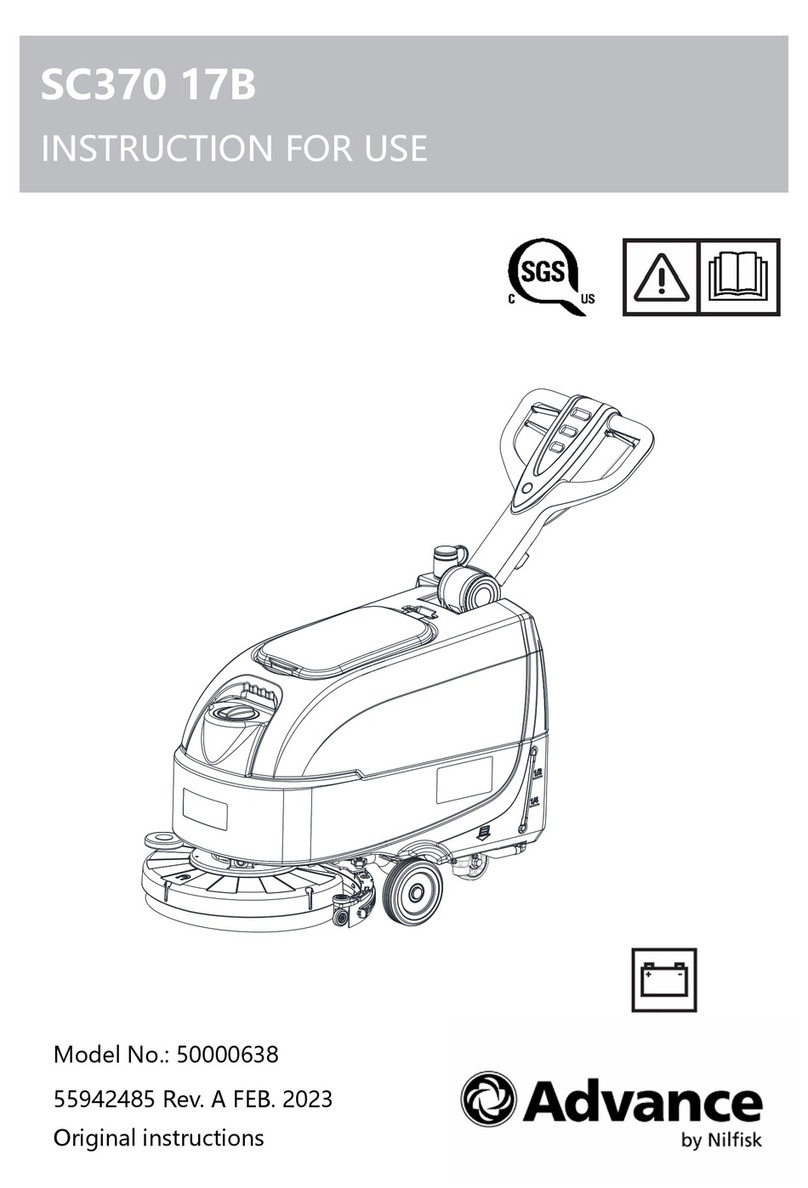
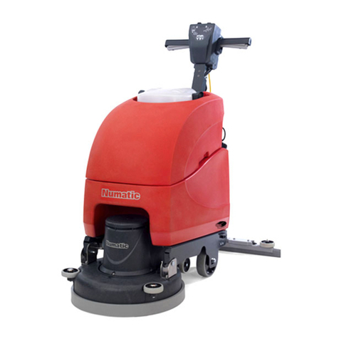
Factory Cat MINI-MAG SERIES User manual

SERVICE MANUAL
R.P.S. Corporation Phone: 1-800-634-4060
P.O. Box 241 Fax: 1-866-632-6961
Racine, Wisconsin
Version 1.0
MINI-MAG SERIES


FOREWORD
i
Factory Cat/Tomcat service manuals are intended for use
by professional, qualified technicians. Attempting repairs
or service without the appropriate training, tools, and equip-
ment could cause injury to you or others and damage to
your piece of equipment that may cause it not to operate
properly
This manual should be kept in a convenient place for easy reference. When properly
used, it will meet the needs of technicians and equipment owners.
No part of this publication may be reproduced, stored in any retrieval system, or trans-
mitted, on any form or by any means, including but not limited to electronic, mechanical,
photocopying, recording or otherwise, with out the prior written permission of the R.P.S.
Corporation. This includes all text, illustrations, tables and charts.
©2006 R.P.S. Corporation
Printed in U.S.A.
As our policy is one of constant improvement, all specifications are subject to change without notice.

CAUTION!
ii
To reduce the chance of personal injury and/or property damage, the following
instructions must be careful observed:
Proper service and repair are important to the safety of the service technician
and the safe reliable operation of all cleaning equipment. If part replacement
is necessary, the part must be replaced with one of the same part number or
with an equivalent part. Do not use replacement parts of lesser quality
The service procedures recommended and described in this service manual
are effective methods of performing service and repair. Some of these
procedures require the use of tools specifically designed for the purpose.
Accordingly anyone who intends to use a replacement part, service procedure
or tool which is not recommended by the equipment manufacturer, must
determine that neither his safety nor the safe operation of the equipment will
be jeopardized by the replacement part, service procedure or tool selected.
It is important to note that this manual contains various cautions and notices
that must be carefully observed in order to reduce the risk of personal injury
during service or repair, or the possibility that improper service or repair may
damage the piece of equipment or render it unsafe. It is also important to
note that these ‘Cautions’ and ‘Notices’ are not exhaustive, because it is
impossible to warn of all the possible hazardous consequences that might
result from failure to follow these instructions.

SAFETY
iii
SAFETY PRECAUTIONS
• Hazardous voltage. Shock, Burns or electrocution can result. ALWAYS disconnect the batteries
before servicing machine.
• Batteries emit hydrogen gases, explosion or fire can result. Keep sparks and open flame away!
• Charge unit in a well ventilated area and keep battery compartment open when charging or
explosion or fire could result.
• Battery acid can cause burns. Wear protective face-shield and gloves when servicing batteries.
• Do not store outdoors or pressure wash. Prevent from getting electrical components wet.
• The use of parts and solutions other than recommended by the manufacturer may cause property
damage, bodily injury or death to yourself or others.
• Dress safely. Do not wear rings, watches or other jewelry while working on this machine. They can
cause an electrical short which can cause serious burns, other injury or death.
• Do not work on this machine while wearing a tie, scarf, hat or any other loose or dangling neck
wear or clothing. Loose clothing can tangle or catch on rotating parts causing serious injury or
death.
• Do not use this machine as a ladder or a chair.
• Operate this machine only from the operators position.
• This machine was not designed to carry passengers or transport cargo.
• Do not operate this machine on steep ramps or uneven surfaces. When climbing a ramp always
drive the machine forward straight up or down the ramp. Never drive across the incline.
• Do not back down or turn on ramps!
• Always use the charger provided by the manufacturer to charge the machine. It is an automatic
charger specifically designed to charge at the appropriate rate. If you must use a different
charger, disconnect the batteries from the machine as this will protect the on-board electronics.
• Understand the dynamic breaking system before you operate the machine on ramps or slopes.
• Do not park the machine on ramps or slopes
• Do not operate the machine if any parts have been removed or damaged.
• Do not remove, paint over, or destroy warning decals. If warning decals become damaged they
must be replaced.
• Do not operate machine in an unsafe condition. If the machine is need of repair or is in anyway
unsafe to operate, the matter should be reported immediately to the shift supervisor. Do not
operate the machine until it is returned to proper operating condition.
• This machine must be operated only by a trained operator. As part of their training they must read
the operators manual thoroughly. If extra copies are needed contact your local dealer.
• Always park machine on a level surface and turn the power off before leaving it unattended.
• Do not operate over electrical floor outlets. This may result in serious injury or death to the
operator and others.
• Do not work under machine without it properly supported on suitable safety stands.
• Do not try and lift this machine unaided it is very heavy.
• Do not use handle bars or steering mechanism as a lifting point

SAFETY
iv
SAFETY MESSAGE
Your safety and the safety of others is very important and operating this unit
safely is an important responsibility.
To help you make informed decisions about safety, we have provided opera-
tion procedures and other safety information in this manual. This information
informs you of potential hazards that could hurt you or others.
It is not practical or possible to warn you of all the hazards associated with
operating this unit. You must use your own good judgement.
This machine is intended for commercial use. It is designed to be used on
hard floors only and in an indoor environment, with the recommended pads
and brushes with approved cleaning solutions.
DO NOT OPERATE THE UNIT:
UNLESS TRAINED AND AUTHORIZED.
UNLESS OPERATOR MANUAL IS READ AND UNDERSTOOD.
IF UNIT IS NOT IN PROPER OPERATING CONDITION.
WHEN OPERATING UNIT:
WEAR PROPER PROTECTIVE EQUIPMENT.
REMOVE LOOSE OBJECTS FROM THE FLOOR THAT MAY BE PROJECTED
FROM THE REVOLVING BRUSHES.
DO NOT OPERATE THE MACHINE WHERE FLAMMABLE LIQUIDS OR GASES
ARE PRESENT.
USE EXTREME CAUTION WHEN MANEUVERING.
MAKE SURE ALL PERSONS ARE A SAFE DISTANCE FROM THE MACHINE
WHILE IN OPERATION.
BEFORE LEAVING THE UNIT:
PARK MACHINE ON A LEVEL SURFACE.
MAKE SURE MACHINE IS TURNED OFF.
DISCONNECT BATTERIES.
BEFORE SERVICING:
STOP ON A LEVEL SURFACE AND SECURE MACHINE.
DISCONNECT BATTERIES.

Mini-Mag Service Manual V1.0
TOC
toc - 1-1
TABLE OF CONTENTS
CONTENTS
MAINTENANCE 1-1
MAINTENANCE SCHEDULE ........................................................ 1-1
LUBRICATION ......................................................................................1-1
MACHINE INRODUCTION 2-1
CONTROLS ................................................................................... 2-1
CHASSIS ....................................................................................... 2-2
BODY ............................................................................................. 2-3
SQUEEGEE SYSTEM 3-1
SQUEEGEE SYSTEM COMPONENTS ........................................ 3-1
SQUEEGEE SUSPENSION BREAKDOWN ........................................3-2
TRIANGLE PLATE & TOW BAR ..........................................................3-3
SIDEWAYS MOVEMENT .............................................................3-3
UP/DOWN MOVEMENT ...............................................................3-3
ORDERING BLADES ...................................................................3-4
REPLACING BLADES .................................................................3-4
SQUEEGEE BLADES ...................................................................3-3
SQUEEGEE ADJUSTMENT .................................................................3-5
PITCH ADJUSTMENT KNOB .......................................................3-5
SQUEEGEE ADJUSTMENT EXAMPLES ....................................3-6
SQUEEGEE LIFT SYSTEM 4-1
TO OPERATE ................................................................................. 4-1
SQUEEGEE LIFT ADJUSTMENTS ............................................... 4-1
SQUEEGEE LIFT ELECTRICAL CIRCUIT ................................... 4-1
BRUSH DRIVE .............................................................................. 4-1
TRACTION DRIVE ........................................................................4-2
RECOVERY SYSTEM 5-1
RECOVERY LID .................................................................................... 5-1
DRAIN SAVER ......................................................................................5-1
VACUUM FLOAT ..................................................................................5-2
BAFFLE ASSEMBLY ............................................................................5-2
DRAIN HOSE ........................................................................................5-2
VACUUM MOTOR .........................................................................5-3
VACUUM SAVER ..........................................................................5-3

Mini-Mag Service Manual V1.0
TOC
toc - 1-2
TABLE OF CONTENTS
SOLUTION SYSTEM 6-1
BRUSH DRIVE .............................................................................. 6-1
DISPENSING SOLUTION ............................................................. 6-1
FILTRATION .................................................................................. 6-1
TRACTION DRIVE ........................................................................ 6-1
SOLUTION SYSTEM ELECTRICAL CIRCUIT .............................. 6-2
BRUSH ASSIST ............................................................................6-2
TRACTION DRIVE ........................................................................6-2
ADJUSTING SOLUTION FLOW - BRUSH ASSIST .............................6-2
ADJUSTING SOLUTION FLOW - TRACTION DRIVE .........................6-2
DRAINING SOLUTION TANK ..............................................................6-3
CLEANING SOLUTION FILTER ...........................................................6-3
BRUSH DRIVE SYSTEM 7-1
DISC ...................................................................................................... 7-1
DISC WITH BRUSH ASSIST ................................................................ 7-1
CYLINDRICAL ..................................................................................... 7-1
BRUSH DRIVE ELECTRICAL CIRCUITS .....................................7-2
BRUSH ASSIST MODELS ...........................................................7-2
SETTING BRUSH PRESSURE ............................................................7-2
BRUSH ASSIST ...........................................................................7-2
TRACTION DRIVE MODELS WITH CENTRAL COMMAND II ....7-3
INSTALLING & REMOVING BRUSHES ....................................... 7-4
DISC MACHINES ..................................................................................7-4
CYLINDRICAL DECK ...........................................................................7-4
BRUSH ASSIST SYSTEM ............................................................. 7-5
BRUSH ASSIST ....................................................................................7-5
BRUSH ASSIST STRENGTH ...............................................................7-5
BRUSH LIFT SYSTEM 8-1
BRUSH ASSIST ............................................................................. 8-1
BRUSH LIFT ELECTRICAL CIRCUIT .......................................... 8-1
DOWN PRESSURE ADJUSTMENT ............................................8-2
TRACTION DRIVE WITH CENTRAL COMMAND II ...................... 8-3
BRUSH LIFT ELECTRICAL CIRCUIT ..........................................8-3
DOWN PRESSURE ADJUSTMENT .............................................8-3
BRUSH LIFT SYSTEM ADJUSTMENTS .............................................8-4
BRUSH LIFT ACTUATOR ....................................................................8-4
ACTUATOR ADJUSTMENT .........................................................8-4
LINKAGE ADJUSTMENT .............................................................8-5
ADJUSTMENT SCREW WITH JAMB NUT. .................................8-5

Mini-Mag Service Manual V1.0
TOC
toc - 1-3
TABLE OF CONTENTS
TRACTION DRIVE SYSTEM 9-1
TRACTION DRIVE ELECTRICAL CIRCUIT ......................................... 9-1
AXLE ..................................................................................................... 9-1
DRIVE MOTOR .............................................................................9-1
TIRES & WHEELS ................................................................................ 9-1
CHASSIS SYSTEM 10-1
CHASSIS REPLACEMENT ......................................................... 10-1
TIRES .................................................................................................. 10-1
CASTERS ........................................................................................... 10-1
BATTERY SAFETY 11-1
DANGER OF EXPLODING BATTERIES ........................................... 11-1
SAFE CHARGING .............................................................................. 11-1
HANDLING BATTERY ACID ..............................................................11-2
WATER ................................................................................................11-2
BATTERY TERMINAL TYPES ............................................................11-2
COMBINATION TERMINAL ........................................................11-3
STUD TERMINAL ....................................................................... 11-3
TAPERED TOP TERMINAL (S.A.E. POST) ...............................11-2
THE “L” TERMINAL ................................................................... 11-3
BATTERY SYSTEM 11-4
BATTERY MAINTENANCE & CARE .......................................... 11-4
LEAD ACID BATTERIES (TRADITIONAL) ........................................11-4
LEAD ACID BATTERIES (MAINTENANCE FREE) ........................... 11-4
GEL CELL BATTERIES ...................................................................... 11-4
BATTERY CABLES & TERMINALS ..................................................11-5
BATTERY TESTING ........................................................................... 11-5
HYDROMETERS ........................................................................11-5
BATTERY REPLACEMENT ...............................................................11-8
BATTERY CHARGERS ............................................................... 11-8
OFF-BOARD CHARGER ....................................................................11-8

Mini-Mag Service Manual V1.0
TOC
toc - 1-4
TABLE OF CONTENTS
ELECTRICAL SYSTEM 12-1
SWITCHES ................................................................................... 12-1
RELAYS ....................................................................................... 12-1
MOTORS ...................................................................................... 12-1
BRUSH DECK MOTORS .................................................................... 12-1
VACUUM MOTOR ...............................................................................12-2
ACTUATORS ............................................................................... 12-2
WIRING ........................................................................................ 12-2
STANDARD CRIMP ON TERMINALS ................................................12-2
MOLEX CONNECTORS .....................................................................12-2
CONTROLLER HIGH AMP OUTPUT TERMINALS ..........................12-3
ANDERSON BATTERY CONNECTORS ............................................12-3
COMPUTER CONTROL SYSTEM 13-1
CONTROLLER OVERVIEW ........................................................ 13-1
INPUTS ............................................................................................... 13-1
OUTPUTS ........................................................................................... 13-1
CONTINUITY TESTING .............................................................. 13-1
PULSE WIDTH MODULATION ................................................... 13-1
SOFT START ..............................................................................13-2
CONNECTIONS ..................................................................................13-2
AMP TERMINALS .......................................................................13-2
BINDING POST TERMINALS ....................................................13-2
MOLEX MINI FIT JR. ..................................................................13-2
TIMED CIRCUITS ................................................................................13-2
BATTERY METER ..............................................................................13-2
DOWN PRESSURE CONTROL .........................................................13-2
LCD DISPLAY .............................................................................. 13-3
SCREEN 1 ..........................................................................................13-3
SCREEN 2 ..........................................................................................13-3
SCREEN 3 ..........................................................................................13-4
SCREEN 4 ..........................................................................................13-4
ON BOARD DIAGNOSTICS ...............................................................13-5
DIAGNOSING THE CONTROL SYSTEM ....................................13-5
METERS .............................................................................................13-5
MEASUREMENTS ......................................................................13-5
LCD DISPLAY .....................................................................................13-5
INPUTS ...............................................................................................13-5
INPUTS- VARIABLE VOLTAGE .................................................13-6
TRI-STATE LOGIC ......................................................................13-6
OUTPUTS ...........................................................................................13-6
PROGRAMMING ......................................................................... 13-7
Mini-Mag Service Manual V1.0
TOC
toc - 1-5
TABLE OF CONTENTS
FLOWCHART DIAGNOSIS ......................................................... 13-8
ALL MACHINES .................................................................................13-8
BATTERY DIAGNOSTICS 1 OF 1 ..............................................13-8
EMERGENGY STOP DIAGNOSTIC 1 OF 1 ...............................13-9
RECOVERY SYSTEM DIAGNOSTICS 1 OF 3 .........................13-10
RECOVERY SYSTEM DIAGNOSTICS 2 OF 3 ......................... 13-11
RECOVERY SYSTEM DIAGNOSTICS 3 OF 3 .........................13-12
SPRAY JET DIAGNOSTICS 1 OF 2 .........................................13-13
SPRAY JET DIAGNOSTICS 1 OF 2 .........................................13-14
BRUSH ASSIST MODELS ........................................................13-15
BRUSH ASSIST DIAGNOSIS 1 OF 1 .......................................13-15
BRUSH DECK ACTUATOR DIAGNOSIS 1 OF 2 .....................13-16
BRUSH DECK ACTUATOR DIAGNOSIS 2 OF 2 ..................... 13-17
BRUSH DRIVE MOTOR DIAGNOSIS 1 OF 2 ..........................13-18
BRUSH DRIVE MOTOR DIAGNOSIS 2 OF 2 ..........................13-19
SOLUTION SYSTEM DIAGNOSIS 1 OF 2 ...............................13-20
SOLUTION SYSTEM DIAGNOSIS 2 OF 2 ............................... 13-21
VACUUM MOTOR DIAGNOSTICS 1 OF 2 ...............................13-22
VACUUM MOTOR DIAGNOSTICS 2 OF 2 ...............................13-23
TRACTION DRIVE W/CCII ......................................................... 13-24
BRUSH DECK ACTUATOR DIAGNOSIS 1 OF 1 .....................13-24
BRUSH MOTOR - DUAL - DIAGNOSIS 1 OF 1 .......................13-26
BRUSH MOTOR - SINGLE - DIAGNOSIS 1 OF 1 ...................13-25
BRUSH PRESSURE SWITCH DIAGNOSIS 1 OF 2 ................ 13-27
BRUSH PRESSURE SWITCH DIAGNOSIS 1 OF 2 ................13-28
BRUSH PRESSURE SWITCH DIAGNOSIS 2 OF 2 ................13-29
BRUSH SWITCH DIAGNOSIS 1 OF 2 .....................................13-30
BRUSH SWITCH DIAGNOSIS 2 OF 2 ..................................... 13-31
BUSS RELAY DIAGNOSIS 1 OF 2 ..........................................13-32
BUSS RELAY DIAGNOSIS 2 OF 2 ..........................................13-33
DRIVE MOTOR DIAGNOSIS 1 OF 1 ........................................13-36
KEY SWITCH DIAGNOSIS 1 OF 1 ........................................... 13-37
LCD DIAGNOSIS 1 OF 1 ..........................................................13-38
PAGE SWITCH DIAGNOSIS 1 OF 1 ........................................13-39
SOLUTION POTENTIOMETER DIAGNOSIS 1 OF 3 ............... 13-41
SOLUTION POTENTIOMETER DIAGNOSIS 2 OF 3 ...............13-42
SOLUTION POTENTIOMETER DIAGNOSIS 3 OF 3 ...............13-43
SOLUTION SOLENOID DIAGNOSIS 1 OF 2 ...........................13-34
SOLUTION SOLENOID DIAGNOSIS 2 OF 2 ...........................13-35

Mini-Mag Service Manual V1.0
TOC
toc - 1-6
TABLE OF CONTENTS
BLANK
THIS PAGE WAS INTENTIONALLY LEFT BLANK

Mini-Mag Service Manual V1.0
1
1-1
MAINTENANCE
MAINTENANCE
MAINTENANCE SCHEDULE
ATTENTION!
Make sure machine is turned off and the batteries are disconnected before performing any
repairs or service on the machine!
Your machine is equipped with up to four brush-type electric motors that require periodic
inspection to assess wear. Failure to inspect on regular intervals can result in motor dam-
age that is not covered under warranty.
LUBRICATION
The machine requires periodic lubrication on each grease fitting on the machine and oiling
of some pivot points and threads. Once a month is generally acceptable unless the ma-
chine is used in a severe duty application.
The grease fittings are located on:
Rear casters
The following points to be oiled lightly are:
Squeegee knob threads
Squeegee adjustment threads
Squeegee pivot points
Brush head pivot points

Mini-Mag Service Manual V1.0
1
1-2
MAINTENANCE

Mini-Mag Service Manual V1.0
1
1-3
MAINTENANCE

Mini-Mag Service Manual V1.0
1
1-4
MAINTENANCE
BLANK
THIS PAGE WAS INTENTIONALLY LEFT BLANK

Mini-Mag Service Manual V1.0
2
2-1
MACHINE INTRODUCTION
1. MAIN POWER SWITCH
2. BATTERY GAUGE
3. SCRUB DECK DOWN PRESSURE GAUGE
4. SPRAY JET SWITCH
5. SCRUB DECK SWITCH
6. KEY SWITCH (OPTIONAL)
7. CIRCUIT BREAKER - 2 AMP
8. CIRCUIT BREAKER - 25 AMP
9. CIRCUIT BREAKER - 40 AMP
10. SPRAY JET SWITCH - (BLUE)
11. FUTURE USE
12. CHARGER PORT
13. HANDLE BAR
14. FORWARD/REVERSE SWITCH - (RED)
15. SOLUTION FLOW CONTROL KNOB
16. LCD SCREEN
17. PAGE BUTTON
18. SCRUB DECK SWITCH
19. DOWN PRESSURE TOGGLE SWITCH
20. WARNING PLATE
21. WARNING PLATE
22. SERIAL NUMBER PLATE
23. SPEED CONTROL KNOB

Mini-Mag Service Manual V1.0
2
2-2
MACHINE INTRODUCTION
24. TRACTION DRIVE
25. SOLUTION FLOW VALVE
26. SOLUTION FILTER
27. WALL ROLLERS
28. “PAD ASSIST” DRIVE ADJUSTMENT KNOB

Mini-Mag Service Manual V1.0
2
2-3
MACHINE INTRODUCTION
29. DRIVE BUTTON
30. “DRAIN SAVER” STRAINER
31. VAC SCREEN
32. CASTER
33. MAIN TIRE
34. JAWS
35. TANK IN A TANK
36. SOLUTION FILL ID
37. RECOVERY LID
38. CLEAR COVER
39. CONTROL PANEL
40. SOLUTION LEVEL DRAIN TUBE
41. VACUUM HOSE
42. SQUEEGEE BLADE
43. SQUEEGEE PITCH ADJUSTMENT
44. “ON-BOARD” BATTERY CHARGER
45. RECOVERY DRAIN HOSE
46. TANK LATCH
BODY

Mini-Mag Service Manual V1.0
2
2-4
MACHINE INTRODUCTION
1. MAIN POWER SWITCH: Turns the machine on and off.
2. BATTERY GAUGE: Indicates the amount of battery charge remaining.
3. SCRUB DECK DOWN PRESSURE GAUGE: Indicates the amount of down pressure being
applied to scrub deck.
4. SPRAY JET SWITCH (BLUE): Turns spray jet pump on,
5. SCRUB DECK SWITCH: Raises and lowers the scrub deck and controls amount of down
pressure being applied.
6. KEY SWITCH (OPTIONAL): Provides key access to turn machine on and off.
7. CIRCUIT BREAKER - 2 AMP resetable circuit breaker - Brush deck actuator
8. CIRCUIT BREAKER - 25 AMP resetable circuit breaker - Vacuum motor
9. CIRCUIT BREAKER - 40 AMP resetable circuit breaker - Brush deck motor
10. SPRAY JET SWITCH - (BLUE): Turns spray jet pump on,
11. FUTURE USE
12. CHARGER PORT: Connection port for attaching external battery charger. NOTE: Only use
charger provided (24 VOLT ONLY!).
13. HANDLE BAR: Adjustable handle bar.
14. FORWARD/REVERSE SWITCH - (RED): Controls the direction of travel for the machine.
15. SOLUTION FLOW CONTROL KNOB: Controls the volume of solution dispensed by the
scrubber.
16. LCD SCREEN: Displays status, settings and function states of the machine.
17. PAGE BUTTON: Scrolls through information on the LCD Screen.
18. SCRUB DECK SWITCH: Raises and lower the scrub deck
19. DOWN PRESSURE TOGGLE SWITCH: Controls the down pressure placed on the scrub
deck.
20. WARNING PLATE: Relays precautions regarding the machine and/or its operation.
21. WARNING PLATE: Relays precautions regarding the machine and/or its operation.
22. SERIAL NUMBER PLATE: Machine identification
23. SPEED CONTROL KNOB: Controls the speed of the traction drive.
24. TRACTION DRIVE: Propels machine forward and backward
25. SOLUTION FLOW VALVE: Meters the flow of solution out the machine.
26. SOLUTION FILTER: Filters particles out of the solution to protect the solution valve.
27. WALL ROLLERS: Helps protect machine and walls when scrubbing in close proximity.
28. “PAD ASSIST” DRIVE ADJUSTMENT KNOB: Adjusts the amount of brush assist given to
then machine. (BRUSH ASSIST MODELS ONLY).
29. DRIVE BUTTON: Controls the drive function of the machine.
30. “DRAIN SAVER” STRAINER: Collects large debris that is picked up by the squeegee.
31. VAC SCREEN: Protects the vacuum motor from debris
32. CASTER: Twin casters for stability.
33. MAIN TIRE: Main tires - Drive tires on traction models.
34. JAWS: Protects scrub deck from collision damage.
35. TANK IN A TANK: Solution/Recovery tank (30 gallons capacity each).
36. SOLUTION FILL LID: Fill port for filling solution tank.
37. RECOVERY LID: Opens to provide full access to the recovery tank.
Table of contents
Other Factory Cat Floor Machine manuals

Factory Cat
Factory Cat 34 User manual

Factory Cat
Factory Cat 29 User manual

Factory Cat
Factory Cat 29 Product manual

Factory Cat
Factory Cat MICRO-HD User manual

Factory Cat
Factory Cat 2023 User manual

Factory Cat
Factory Cat Pilot 28'' DISK User manual

Factory Cat
Factory Cat 48 Series Product manual

Factory Cat
Factory Cat 34 Quick start guide

Factory Cat
Factory Cat 34HD User manual

Factory Cat
Factory Cat 390 Series User manual