fafnir TORRIX XTS Series Guide

Technical Documentation
FAFNIR GmbH • Schnackenburgallee 149 c • 22525 Hamburg • Germany • T.: +49 /40 / 39 82 07-0 • Web: www.fafnir.com
TORRIX … XTS …
Magnetostrictive Level Sensor with Display
Edition: 2023-04
Version: 1
Art. no.: 350372

I Table of contents
Table of Contents
1Characteristics........................................................................................................ 1
1.1 TORRIX XTS Variants..........................................................................................................................2
2Safety Instructions ................................................................................................3
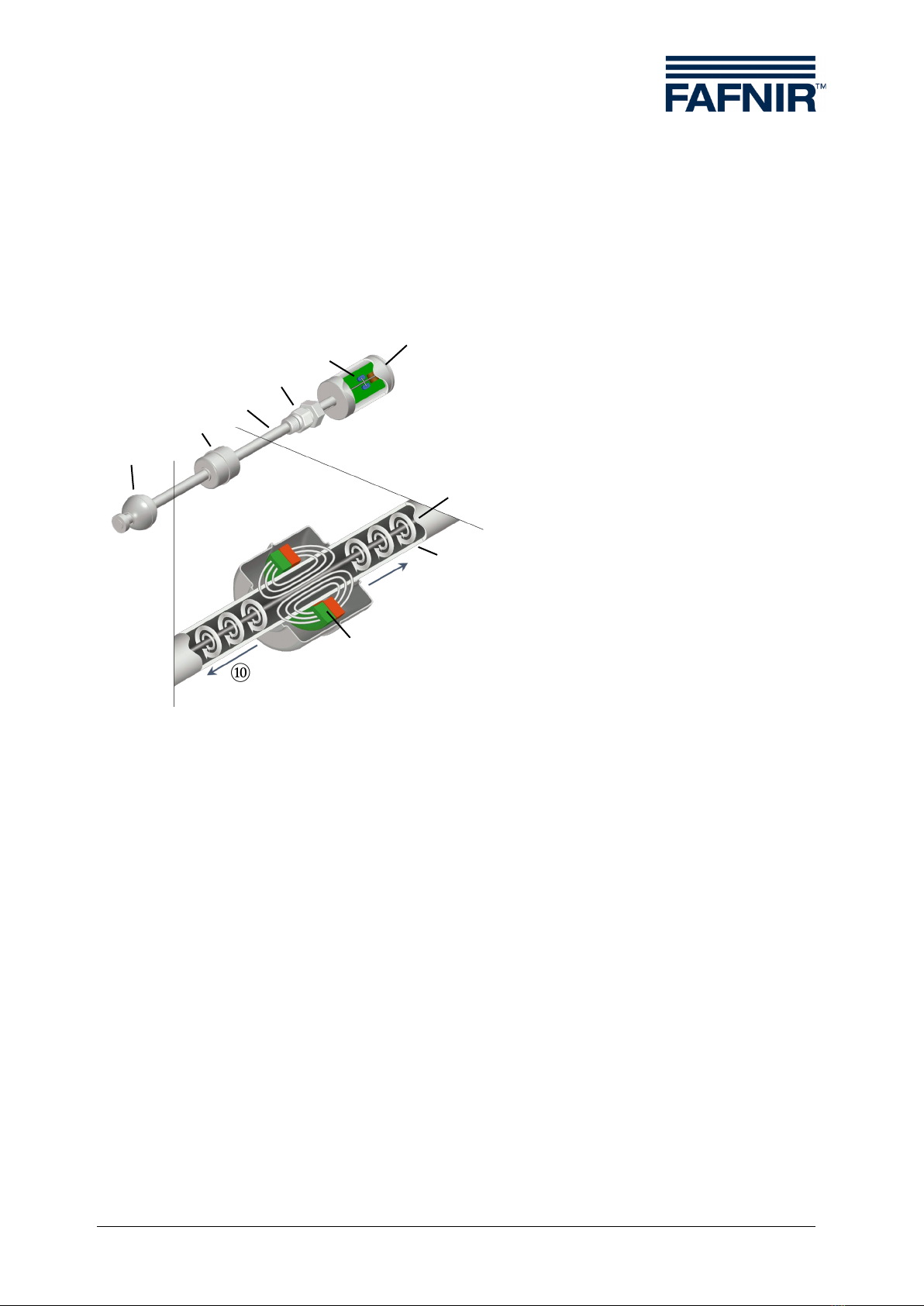
3Design and Function ............................................................................................4
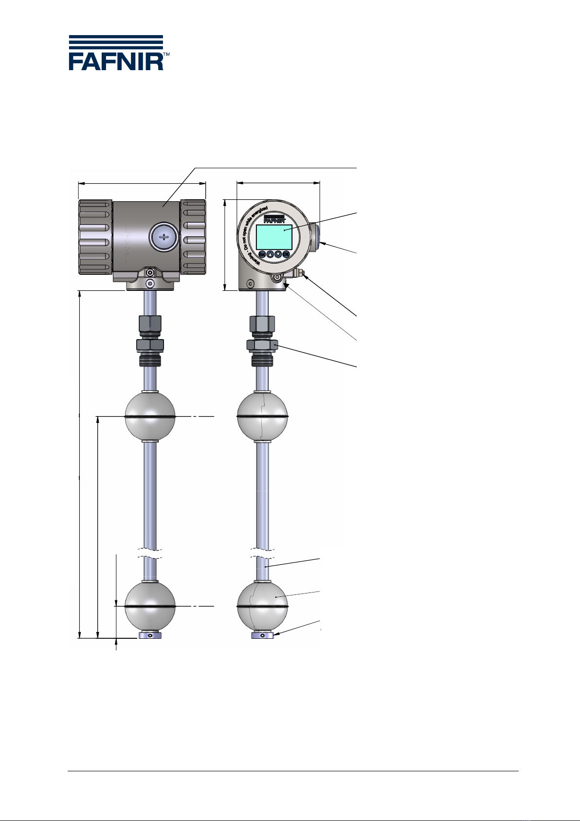
3.1 TORRIX XTS with Screw Connection............................................................................................5
3.2 TORRIX XTS with Flange ..................................................................................................................6
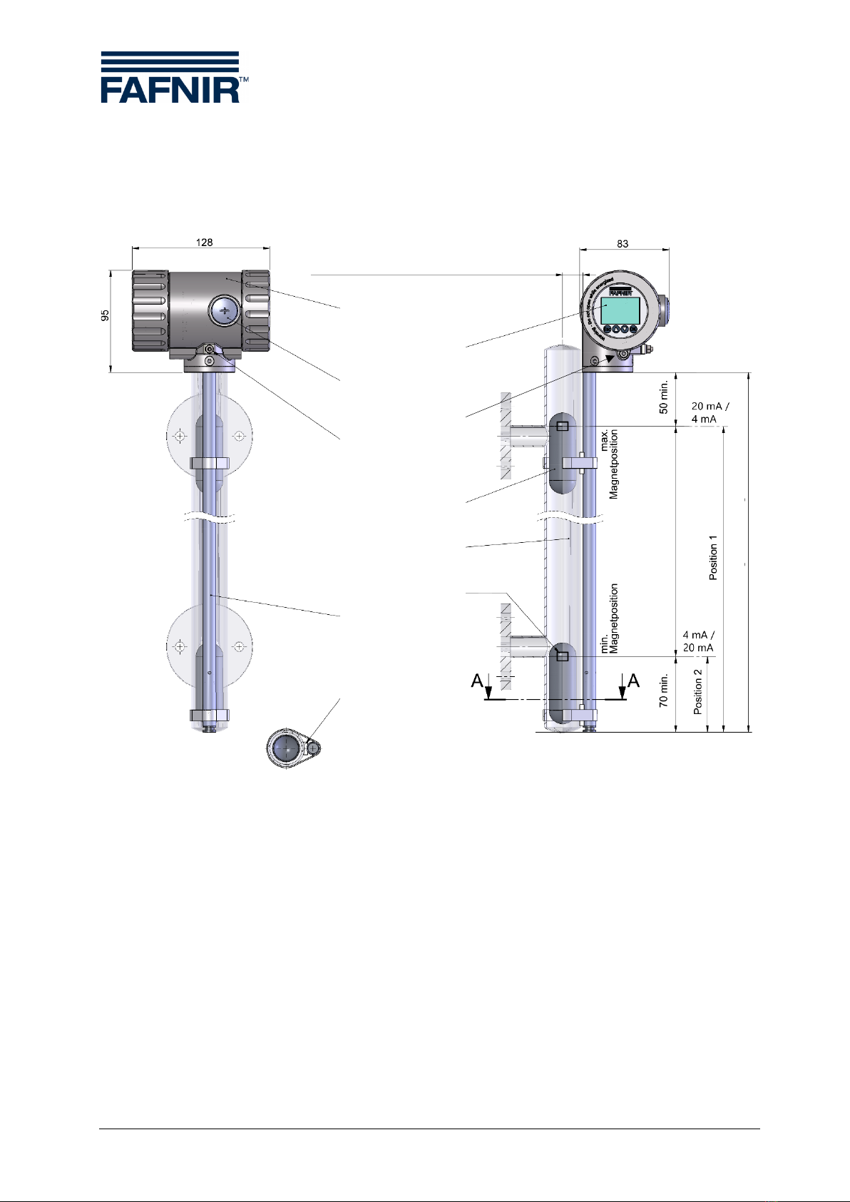
3.3TORRIX XTS for Bypass.....................................................................................................................7
4Installation ..............................................................................................................8
4.1 Installation with screw-in unit .......................................................................................................9
4.2 Installation with flange...................................................................................................................10
5Electrical connection ...........................................................................................11
5.1 Connection Diagrams.....................................................................................................................11
5.1.1Wiring diagram TORRIX XTS ........................................................................................................11
5.1.2 Wiring diagram TORRIX Ex XTS...................................................................................................12
5.1.3 Wiring diagram TORRIX Exd XTS................................................................................................13
5.2 Maximum Length of the Connection Cable ...........................................................................14
5.3 Wiring ...................................................................................................................................................15
5.3.1 Wiring the TORRIX (Ex) XTS..........................................................................................................16
5.3.2 Wiring the TORRIX (Exd) XTS with Heater...............................................................................17
6Indication and adjustment module................................................................18
6.1 Rotation of the display and adjustment module..................................................................18
6.2 Operation ............................................................................................................................................18
6.2.1 Arrangement of the keys / magnet sensors...........................................................................19
6.2.2 Function of the keys / magnet sensors....................................................................................19
6.3 Measured value display .................................................................................................................20
6.4Simulation ...........................................................................................................................................21
6.5 Error display .......................................................................................................................................22
6.6 Icons......................................................................................................................................................22
7Adjustment .......................................................................................................... 23

Table of contents II
7.1 TORRIX XTS Configuration............................................................................................................23
7.2 Menu Structure .................................................................................................................................25
8Maintenance........................................................................................................28
8.1 Servicing ..............................................................................................................................................28
8.2 Return Shipment...............................................................................................................................28
9Technical Data .....................................................................................................29
9.1 Sensor...................................................................................................................................................29
9.2 Float ......................................................................................................................................................30
10 List of Figures .......................................................................................................31
11 Annex ....................................................................................................................32
11.1 EU Declaration of Conformity .....................................................................................................32
11.2 EU-Type Examination Certificate ................................................................................................33
11.3 Instructions.........................................................................................................................................41
© Copyright:
Reproduction and translation are permitted solely with the written consent of the FAFNIR GmbH. The FAFNIR GmbH
reserves the right to carry out product alterations without prior notice.

Page 1/47 Characteristics
1Characteristics
The TORRIX ... XTS ... is a high-precision level sensor from the TORRIX series with an addi-
tional display (XTS) for showing up to 3 different TORRIX measured values on the sensor
head.
The sensor has been developed for continuous level measurement of liquid media in con-
tainers. The measuring principle of the sensor uses the physical effect of the magneto-
striction and is largely unaffected by the temperature. This method is particularly ideal where
level measurements are required to be extremely accurate, such as in the chemical industry.
The TORRIX XTS is available with the following (optional) features:
•Media-contacting probe tube of stainless steel (standard), Hastelloy or titanium
•Straight probe tube with probe tube diameter 12 mm
•Probe lengths from 200 mm to 6 m, as Flex version up to 22 m
•Output signal 4-20 mA and RS-485 serial interface
•Communication via the HART® protocol
•With temperature measurement
•Use in potentially explosive areas with device protection levels Ga (Zone 0 only
with intrinsically safe version), Ga/Gb (Zone 0/1) or Gb (Zone 1)
•Process connection as screw-in unit, flange or bypass
The different TORRIX XTS variants are listed in the table on the next page.
For information about the installation of the TORRIX XTS Flex, see:
TORRIX Flex Installation Guide multilingual, art. no. 350118
For the TORRIX device types without a display, see the technical documentation:
TORRIX (with side cable connection), art. no. 350335
TORRIX M12 (with M12 connector), art. no. 350164

Characteristics Page 2/47
1.1 TORRIX XTS Variants
Type
Approval
Electrical
version
Design
Measuring
accuracy
Mechanical
design
Process temperature
HHT
Maximum temperature -40 °C … +450 °C
HT
High temperature -40 °C … +250 °C
LT
Low temperature -65 °C … +125 °C
NT
Normal temperature -40 °C …(+85) +125 °C
Rigid sensor tube with 12 mm diameter
B
Sensor tube not centered on the sensor head (Bypass)
Flex ...
Flexible sensor tube (... rigid parts: F = 200/ 300 mm; T = 500 mm)
HY
Construction for use in the hygiene area
PL
Plastic coating against very aggressive media
Standard
-5T
With five temperature sensors
-A5T
Increased measurement accuracy and five temperature sensors
-A
Increased measurement accuracy (Advanced)
Standard construction
VT
Internal structure vibration resistant for portable tanks
XTS
RS-485 and 4 … 20 mA interface with HART protocol and setting button and digital display
XTSH
RS-485 and 4 … 20 mA interface with HART protocol, setting button, digital display and heating
(only Exd and without Ex)
Without Ex approval
Ex
With Ex approval intrinsic safety "ia"
Exd
With Ex approval flameproof enclosure "d" or protection by housing "t" and intrinsic safety "ia" for "... XT..."
TORRIX magnetostrictive level sensor with connection terminals or plugs
Example:
TORRIX Ex XTS B is a TORRIX XTS with Bypass assembly for use in hazardous areas.

Page 3/47 Safety Instructions
2Safety Instructions
The TORRIX XTS level sensor has been developed for level measurement of liquids in con-
tainers. The level sensor must be used exclusively for this purpose. The manufacturer accepts
no liability for any form of damage resulting from improper use.
The level sensor has been developed, manufactured and tested in accordance with the latest
good engineering practices and generally accepted safety standards. Nevertheless, hazards
may arise from its use. For this reason, the following safety instructions must be observed:
•Do not change or modify the level sensor or add any equipment without the prior
consent of the manufacturer.
•The installation, operation and maintenance of the level sensor only be carried out
by expert personnel. Specialised knowledge must be acquired by regular training.
•Operators, installers and service technicians must comply with all applicable safety
regulations. This also applies to any local safety and accident prevention regula-
tions which are not stated in this guide.
The safety instructions in this guide are marked as follows:
If these safety instructions are not observed, it may result in the risk of acci-
dent or damages to the TORRIX XTS level sensor.
Useful information which ensures continued and correct operation of the
TORRIX XTS level sensor and makes your work easier.
REACH Regulation
The TORRIX sensors contain a lead-titanium-zirconium-oxide, which belongs to
the substances of very high concern (SVHC) according to Regulation (EG) No.
1907/2006 (REACH). A corresponding note can be found on our website at:
www.fafnir.com.

Design and Function Page 4/47
3Design and Function
The level sensors consist of a probe head (1) and a probe tube (4) made of stainless steel.
The probe tube is height-adjustable with a screw-in body (3) or mounted with a flange in
the tank or outside the tank as a bypass. A float (5) for measuring the product filling level
and another float (6) for continuous interface measurement move on the probe tube.
Figure 1: How the magnetostrictive measuring principle works
The sensor operates according to the magnetostrictive measuring principle. The probe tube
contains a wire (7) made of magnetostrictive material. The sensor electronics (2) transmit
pulses through the wire, which generate a circular magnetic field (8). Permanent magnets
(9) are used as filling level sensors which are installed in both the product float (5) and the
interface float (6). The magnetic field of the float magnets (9) axially magnetises the wire in
this area. The superposition of the two magnetic fields produces a torsional wave (10) at the
float position, which then propagates along the wire in both directions. One torsion pulse
runs directly to the probe head and the other one is reflected at the bottom end of the
probe tube. The time between the current pulse being transmitted and the two torsion
pulses arriving at the probe head is measured and the float position calculated. The position
of the interface float float is calculated by measuring a second pulse.
1 – Probe head
2 – Sensor electronics
3 – Screw-in unit
4 – Probe tube
5 – Product float
6 – Interface float
7 – Magnetostrictive wire
8 – Circular magnetic field
9 – Permanent magnet
10 – Torsion pulse
①
②
③
④
⑤
⑥
⑦
⑧
⑩
⑨
⑩

Page 5/47 Design and Function
3.1 TORRIX XTS with Screw Connection
Figure2: TORRIX XTS (with screw connection)
128
Sondenlänge / Probe length
Position 2
Position 1
Sondenkopf /
Probe head
4 mA /
20 mA
20 mA /
4 mA
91
83
Erdungs-
anschluss /
Earth connector
Verschluss-
schraube /
Screw plug
M20×1,5
Displayeinheit /
Display module
Sondenrohr /
Probe tube Ø12
Schwimmer /
Stellring demontierbar /
Guard ring dismountable
Verschraubung
nach Auftrag /
Screw connection
on order
Probe length
Probe head
Display unit
Screw plug
M20x1.5
Earth connector
Locking screw
Screw connection
on order
Probe tube Ø12
Product float
Guard ring dismountable

Design and Function Page 6/47
3.2 TORRIX XTS with Flange
Figure3: TORRIX XTS F (Flange)
Probe head
Display unit
Screw plug
M20x1.5
Earth connector
Locking screw
Flange depending on order
Probe tube Ø12
Product float
Guard ring dismountable
Installation length on order

Page 7/47 Design and Function
3.3 TORRIX XTS for Bypass
Figure 4: TORRIX XTS B (Bypass)
Distance probe tube to float centre:
max. distance depending on the bypass float
Probe length
Measuring range
Probe head
Display unit
Screw plug
M20x1.5
Locking screw
Earth connector
Bypass float
Bypass tube
Magnet position
Probe tube stressfree
mounted (undeformed)
Spacer
Probe mounting
(non-magnetic)
SECTION A-A
SCALE 1:2

Installation Page 8/47
4Installation
This section describes how to install the level sensor depending on the type of the device
(see the following figures).
When installing and maintaining the level sensor in potentially explosive areas,
the national rules must be observed (Explosion Protection Regulations, Indus-
trial Health and Safety Regulations, Equipment Safety Regulations and specific
conditions of the EU-Type Examination Certificates). The generally accepted
rules of engineering and these operating instructions must be observed.
This also applies to any local safety and accident prevention regulations which
are not stated in this manual.
During installation, take great care not to bend the probe tube, and protect the
float from shock and impact loads.
Installing a level sensor in areas exposed to a powerful external magnetic field
is not permitted because this could impair gauging.
The level sensor can also be fitted into containers from underneath.
If the container additionally is pressurized, then the maximum length of the level
sensor is 2 m.
If the float was removed during installation, it must be slid back onto the probe
tube afterwards with the “TOP” marking oriented towards the probe head to
enable correct measurements.

Page 9/47 Installation
4.1 Installation with screw-in unit
Insert the level sensor into the tank (see following figure):
(1) Loosen both set screws, remove circlip (1) and float (2) from probe tube (3).
Figure 5: Installation with screw-in unit
Removing the float is required only if it does not fit through the installation
opening in the tank. Otherwise, please proceed directly with mounting steps
3, 6 and 7.
(2) If necessary, slide the screw-in unit (4) on the probe tube.
(3) Insert the level sensor into the tank, provide the screw-in thread (4) with a suitable
sealing material, screw it in and tighten.
(4) Slide the float (2) back onto the probe tube (3).
For correct gauging, the float must be slid onto the probe tube with the “TOP”
marking oriented towards the probe head, to enable a correct measurement.
(5) Refit the circlip (1) on the tube, align the set screws over the groove and tighten.
(6) Adjust the height of the process connection and fix the union nut (5) finger tight
by hand.
(7) Fix the union nut (5) with a 1 ¼ clockwise turn (see following figure).
Figure 6: Tightening the compression fitting
1
2
3
5
4
5

Installation Page 10/47
4.2 Installation with flange
The probe tube is firmly welded to the flange, so the installation length cannot be changed.
Fasten flange and seal with the flange bolts and nuts. The screws or nuts and the seals are
the responsibility of the operating company and must be chosen depending on the fluid.
The fasteners and seals must comply with the requirements of the standards EN 1092-1, EN
1514 and EN 1515.
If the float does not fit through the installation opening, see installation instructions, see
chapter 4.1.

Page 11/47 Electrical connection
5Electrical connection
5.1 Connection Diagrams
5.1.1 Wiring diagram TORRIX XTS
The level sensor without Ex approval is installed according to the following wiring diagram:
Figure 7: Wiring diagram TORRIX XTS
Maximum power supply Umax = 50 VDC
Minimum supply voltage Umin = 12 VDC
Permissible total resistance (incl. line resistances and load)
ΣR = (U - Umin) / 0.0215 A
Example:
Standard supply voltage of 24 VDC with a negative tolerance value of -5%
ΣR = (24 VDC x 0.95 – 12 VDC) / 0.0215 A = 502 Ω
The permissible total resistance is about 500 Ω.
+
+
_
Y
I
R1
R2
R3
U
TORRIX
Spannungsquelle
Leitungswiderstände
Bürde
U= 30 V
max
U = 8 V
min
Line resistances
Power supply
Power supply
Umax = 50 VDC
Load
Umin = 12 V
DC
Line resistances
TORRIX XTS

Electrical connection Page 12/47
5.1.2 Wiring diagram TORRIX Ex XTS
The level sensor TORRIX Ex XTS with Ex i approval (intrinsically safe) is installed in a poten-
tially explosive atmosphere according to the following wiring diagram:
Figure 8: Wiring diagram TORRIX Ex XTS
Maximum power supply Umax = 30 VDC
Minimum supply voltage Umin = 12 VDC
Permissible total resistance (incl. line resistances and load)
ΣR = (U - Umin) / 0.0215 A
The TORRIX Ex level sensor may be connected in potentially explosive atmos-
pheres in the intrinsically safe version only to associated equipment that have
been certified by a recognised inspection authority and whose electrical output
data meets the following conditions:
Uo≤30 VDC
Io≤100 mA / 200 mA (depending on the ambient temperature Ta)
Po≤1 W
Always make sure that the permissible external capacitance (Co) and inductance
(Lo) of the associated apparatus are not exceeded (refer to the electrical data in
the EU-Type Examination Certificate of the apparatus) if used in a potentially
explosive atmosphere.
The connecting cable to the associated apparatus must be marked if used in po-
tentially explosive atmosphere, preferably as blue cable for intrinsically safe elec-
tric circuits.
Further data of the EU Type Examination Certificate can be found in the ap-
pendix of this manual.
Y
I
+
-
R1
R2
TORRIX(Ex-Ausführung)
Leitungswiderstände
Trennverstärker(Beispiel)
Hilfsenergie
4...20 mA
+
-
4...20 mA
8...30 V
Isolating amplifier (example)
12 … 30 VDC
4 … 20 mA
TORRIX Ex XTS
Power Supply
Line resistance
4 to 20 mA

Page 13/47 Electrical connection
5.1.3 Wiring diagram TORRIX Exd XTS
The TORRIX Exd XTS level sensor with Ex d approval is installed in a potentially explosive
atmosphere according to the following wiring diagram:
Figure 9: Wiring diagram TORRIX Exd XTS
Maximum power supply Umax = 50 VDC
Minimum supply voltage Umin = 12 VDC
Permissible total resistance (incl. line resistances and load)
ΣR = (U - Umin) / 0.0215 A
The TORRIX Exd XTS level sensor may be connected in potentially explosive at-
mospheres in this version to all associated equipment whose electrical output
data meets the following conditions:
U ≤50 VDC
Um= 253 V
I = 4 mA … 20 mA
In the event of an error, the current can also be 3.6 or 21.5 mA.
A certified Ex d or Ex t cable gland (depending on the application) must be
used for the TORRIX Exd XTS.
Further data of the EU Type Examination Certificate can be found in the ap-
pendix of this manual.
+
+
_
Y
I
R1
R2
R3
U
TORRIX
Spannungsquelle
Leitungswiderstände
Bürde
U = 30 V
max
U = 8 V
min
TORRIX Exd XTS
Power supply
Umax = 50 VDC
12 … 50 VDC
4 … 20 mA
Line resistances
Load

Electrical connection Page 14/47
5.2 Maximum Length of the Connection Cable
The permissible total resistance of the cable and the load (see chapter 5.1.1) must not be
exceeded.
The cable (length and cross-section) must be chosen so that the supply voltage
will not fall below the sensor-specific minimum voltage (12 V) in the case of
the highest current consumption (21.5 mA).
Always make sure that the permissible external capacitance (Co) and inductance
(Lo) of the associated apparatus are not exceeded (refer to the electrical data in
the EU-Type Examination Certificate of the apparatus) if the intrinsically safe
level sensor is used in a potentially explosive atmosphere.
The following table shows the resistances of different copper wire cross-sections:
Cable cross-section Q [mm²]
Cable resistance RQper m copper cable [Ω/m]
0.5
0.0356
1.0
0.0178
1.5
0.0119
Example: A 1000 m long, cross-section 0.5 mm² copper cable with outgoing and return
lines (2-core) has a cable resistance of approximately 70 Ω.
The maximum cable length is calculated as follows:
L = (((U – Umin) / Imax) –RB) / RQ
L = Cable length [m]
U = Supply voltage [V] (with negative tolerance value -5%)
Umin= Minimum supply voltage [V] = 12 VDC
Imax = Maximum power consumption [A] = 0,0215 A
RB= Load
RQ= Cable resistance per m cable [Ω/m] for cable cross-section Q [mm²]
Example:
Supply voltage = 24 VDC (± 5 %), supply voltage U = 22.8 VDC (24 VDC - 5%),
minimum supply voltage Umin = 12 VDC, current consumption Imax = 0.0215 A,
load RB= 100 Ω, cable cross-section Q = 0.5 mm², cable resistance RQ= 0.0356 Ω/m
A copper cable with outgoing and return lines (2-core) could theoretically be up to 5650 m
long with the parameters of this example.

Page 15/47 Electrical connection
5.3 Wiring
The TORRIX XTS level sensors may only be wired with the power disconnected.
The terminal compartment is accessible after removing the rear screw cover from the probe
head. To do this, screw the locking screw of the cover into the housing with a 3 mm Allen key.
After the wiring has been completed, the cover must be screwed on again and secured
against unintentional loosening.
The electrical connection is made using the push-in PCB terminal clamps.
Fine-wire conductors with wire-end ferrules and single-wire conductors can be plugged in
directly. The terminal clamps can be unlocked with a screwdriver to insert or remove the
conductors. The blade width should be 3.5 x 0.5 mm.
The permissible cable cross-section for single-wire conductors is in the range of 0.5 to 2.5
mm2(20 to 12 AWG). A cable cross-section in the range of 0.5 to 1.5 mm2is permissible for
fine-wire conductors with wire-end ferrules.
For the wiring, continue as follows:
•insert the connection cable through the lateral opening into the terminal com-
partment, the TORRIX Ex… requires a certified cable gland
•connect the connection cable to the right PCB terminal clamps
The earthing or equipotential bonding must be carried out by the installer in
accordance with the respective national installation regulations. The earth con-
nector of the probe head can be used for earthing or equipotential bonding re-
quirements.
Also observe the general installation regulations.

Electrical connection Page 16/47
5.3.1 Wiring the TORRIX (Ex) XTS
Figure 10:Terminal compartment of TORRIX (Ex) XTS
Signal
Connection
Used internally A
Sensor voltage +
Sensor voltage
–
Used internally B
Pin assignment of the 4-pin PCB terminal clamp in the terminal compartment
The connection cable between the (intrinsically safe) TORRIX (Ex) XTS and the associated
equipment must have the following properties:
•2-wire unshielded cable
•For Ex ia applications the colour blue or marked blue
(cable for intrinsically safe power circuits)
A + - B

Page 17/47 Electrical connection
5.3.2 Wiring the TORRIX (Exd) XTS with Heater
Figure 11:Terminal compartment of TORRIX (Exd) XTS
Signal
Connection
Used internally A
Sensor voltage +
Sensor voltage
–
Used internally B
Pin assignment of the 4-pin PCB terminal clamp in the terminal compartment
For the extended temperature range (-55 °C to +85 °C), the TORRIX (Exd) XTS is additionally
equipped with a heater for the display. The supply voltage for the heater is connected to the
2-pin PCB terminal clamp.
Signal
Connection
Heater voltage +
Heater voltage
–
Pin assignment of the 2-pin PCB terminal clamp in the terminal compartment
A + - B
+ -
Table of contents
Other fafnir Accessories manuals