fafnir CONDURIX Series Guide

FAFNIR GmbH • Schnackenburgallee 149 c • 22525 Hamburg, Germany • Tel.: +49 / 40 / 39 82 07–0 • Fax: +49 / 40 / 390 63 39
Technical Documentation
CONDURIX
The potentiometric level sensor
Edition: 2016-08
Version:
9
Art. no.:
207134

I Table of Contents

Table of Contents II
Table of contents
1Range of application.............................................................................. 1
2Safety instructions ................................................................................. 2
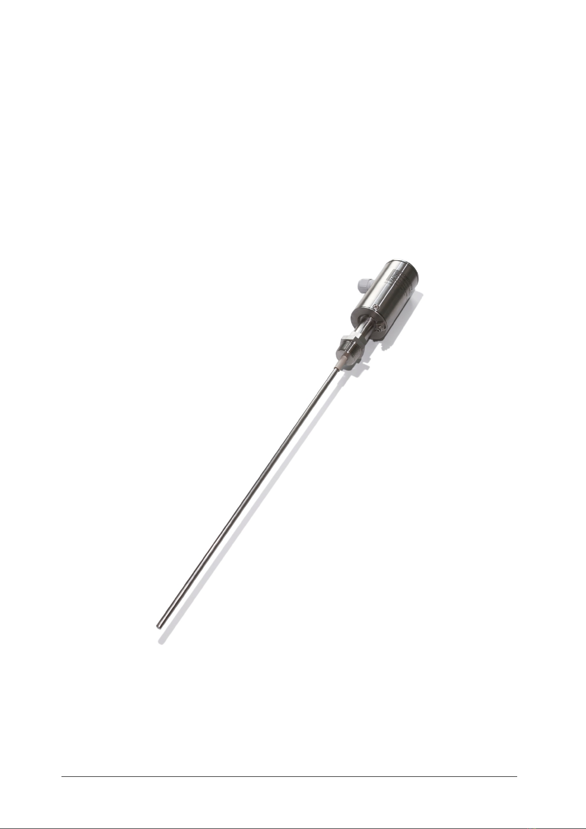
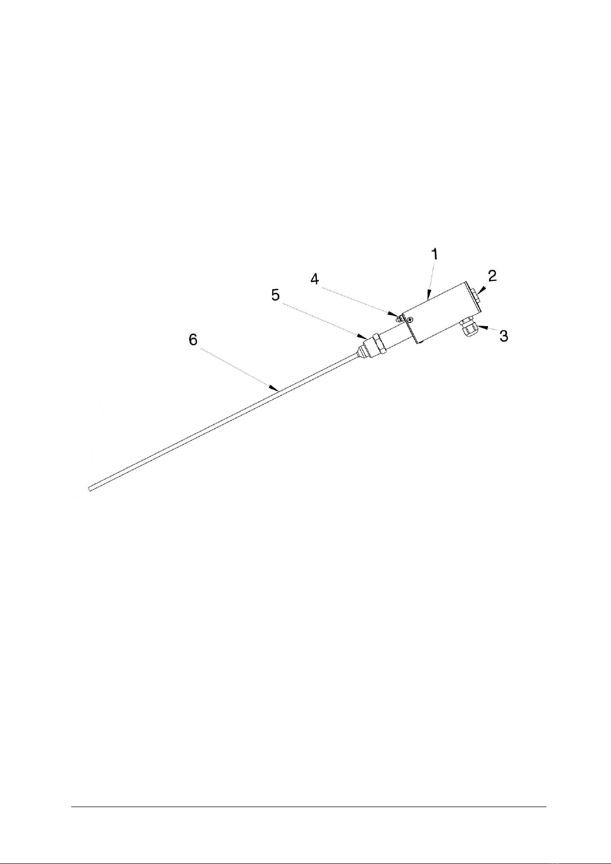
3Design and function............................................................................... 3
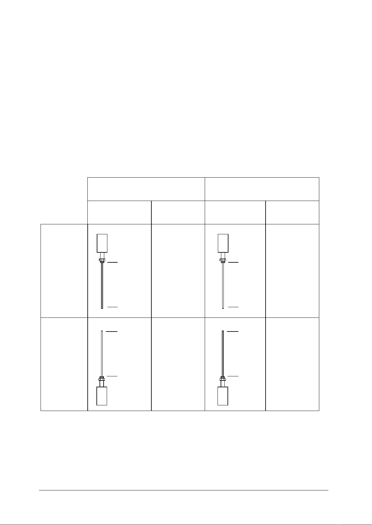
4Installation.............................................................................................. 5
4.1 CONDURIX Mono (single rod).............................................................................6
4.2 CONDURIX DU (two rods)...................................................................................6
4.3 CONDURIX MA (jacketed pipe)...........................................................................6
5Electrical connection .............................................................................. 7
6Parametrisation ...................................................................................... 9
6.1 Measuring span at the level sensor .....................................................................9
6.2 Current consumption in failure mode ...............................................................10
7Maintenance......................................................................................... 11
7.1 Overhaul ..........................................................................................................11
7.2 Return shipment...............................................................................................11
8Technical Data ...................................................................................... 12
9List of figures........................................................................................ 13
10 Annex.................................................................................................... 14
10.1 EC Declaration of Conformity ...........................................................................14
10.2 EC-Type Examination Certificate .......................................................................15
10.3 Safety instructions ............................................................................................18
© Copyright:
Reproduction and
translation are permitted only with the written consent of the FAFNIR GmbH. FAFNIR GmbH reserves
the right to make changes to products without prior notice.

Page 1/20 Range of application
1Range of application
The purpose of the CONDURIX level sensor is to provide continuous level gauging of elec-
trically conductive liquids (> 1 μS/cm). During the measurement no insulating layer must
be formed on the probe tube.
The level sensor is available in lengths of 200 to 6,000 mm.
With the “single-rod probe” model (CONDURIX Mono), the inside of the container must
have a conductive surface (metal containers / downpipes). The “two-rod probe” model
(CONDURIX DU) or “jacketed probe” model (CONDURIX MA) are both compatible with
non-conductive containers.
The standard sensors work by outputting the measured fill level as an analogue value in
the range 4 to 20 mA.
With the HART option, the configuration and retrieval of measured values by the digital
HART protocol are supported, see
•Technical Documentation CONDURIX with HART protocol, art. no. 350044
In conjunction with the standard level sensors, wetted parts are in stainless steel 1.4571
(316Ti), insulators are in PEEK (alternatively in PTFE). On request, the probe tubes are also
available in Hastelloy, tantalum, titanium or stainless steel 1.4404 (316L).

Safety instructions Page 2/20
2Safety instructions
The purpose of the CONDURIX level sensor is to provide continuous level gauging of liq-
uids. The level sensor must be used exclusively for this purpose. The manufacturer accepts
no liability for any form of damage resulting from improper use.
The level sensor has been developed, manufactured and tested in accordance with the
latest good engineering practices and generally accepted safety standards. Nevertheless,
hazards may arise from its use. For this reason, the following safety instructions must be
observed:
Do not change or modify the level sensor or add any equipment without the prior con-
sent of the manufacturer. The installation, operation and maintenance of the level sensor
must be carried out only by expert personnel. Operators, installers and service technicians
must observe all applicable safety regulations. This also applies to any local safety and
accident prevention regulations which are not stated in this manual.
The safety instructions in this manual are marked as follows:
If these safety instructions are not observed, it may result in the risk of acci-
dent or damages to the CONDURIX level sensor.
Useful information designed to ensure continued and correct operation of
the CONDURIX level sensor or helpful advice to make your work easier.

Page 3/20 Design and function
3Design and function
The design of the CONDURIX level sensor is illustrated in Figure 1 with the screw-in unit
version as an example. Inside the sensor head (1) of the level sensor and concealed by a
cap (2) are the protected terminals and configuration buttons. The electrical connection is
established by means of an M16x1.5 screwed cable gland (3) and screw terminals or by
an M12 plug-in connection. The potential equalization terminal (4) is required only in
conjunction with the CONDURIX Mono version (see section 5 Electrical connection). On
the probe neck, there is either a screw-in unit (5) or a flange (not shown) for installing the
probe in the container.
Figure 1: The CONDURIX level sensor
A current pulse generates a linear voltage drop (< 100 mV) on the probe tube (6) electri-
cally insulated from tank potential. The voltages at the bottom end and top end of the
tube are measured.
As long as the probe tube is not immersed, it has no path to tank potential. This state is
detected by the signal processor, which outputs an “empty” signal. As soon as the probe
tube is immersed, the voltage measured at the immersed tube end corresponds to tank
potential and the voltage measured at the top end is added to the voltage drop along the
non-immersed part of the probe tube.
With the probe tube fully immersed, the voltages measured at the top and bottom ends
of the tube are equal in respect of the potential reference point. The region in between is
mostly linear, depending on the tank geometry and the distance between the tube end
and tank bottom, which makes it possible to calculate the fill level from the ratio of the
measured voltages.

Design and function Page 4/20
The fill level is calculated from the ratio of the measured voltages by a microcontroller.
The ratio of the two voltages also enables the orientation of the CONDURIX sensor to be
detected, i.e. whether the sensor has been installed from top down or bottom up.
The level sensor is fed from a 2-wire 4 … 20 mA interface and requires a voltage of
between 8 and 30 V. The position of 4 mA and 20 mA points on the probe tube is freely
adjustable (see chapter 6, Parametrisation). To prevent galvanic processes from occurring
in the liquid, both the discharging and charging currents flow through a galvanically
isolating transformer. The alternating voltage produced across the very low-resistance
probe tube is in the 100 mV range.
The table below shows the signal characteristics of the sensor as a function of sensor ori-
entation and the measured value output setting (normal/inverted).
Measured value output
normal
Measured value output
inverted
Filling level
“Empty” sig-
nal
Filling level
“Empty” sig-
nal
Installation
top down
3.8 mA
20.5 mA
Installation
bottom up
3.8 mA
20.5 mA
Figure 2: Measured value output
Installation top down: The zero point is at the probe base
Installation bottom up: The zero point is at the sensor head
Normal measured value output: The 20 mA point is higher than the 4 mA point
Inverted measured value output: The 20 mA point is lower than the 4 mA point
20 mA
4 mA
4 mA
20 mA
20 mA
4 mA
4 mA
20 mA

Page 5/20 Installation
4Installation
All local safety and accident prevention regulations not expressly referred to
herein must be observed.
Figure 3: CONDURIX variants
Level gauging with CONDURIX is possible only in electrically conductive
liquids.
The level sensor can also be fitted into the tank from underneath. The
sensor must be configured accordingly.
CONDURIX Mono: If the probe tube is immersed in the liquid only a short
way, the linearity of the measurement is affected by the short distance
between the probe tube and reference potential.
AMXIRUDNOC CONDURIX DU
50
~160
29
50
112
8
onoMXIRUDNOC 50
ca. 161
5
Cap, SW 19
removable
Cable
gland
M16x1.5
Sensor head
Connector for
equipotential bonding
Jacketed pipe
Probe tube
Cap, SW 19
removable
Cable
gland
M16x1.5
Sensor head
Connector for
equipotential bonding
Screw-in
unit R ¾ min.
or flange
Flange or
screw-in unit R 2
Probe tube
∅6
Counter electrode
∅24
Measuring range Adjustment range
Measuring range
Measuring range
Installation length
Installation length

Installation Page 6/20
4.1 CONDURIX Mono (single rod)
With the single-rod probe, the tank acts as the counter electrode. For this reason, the
material on the inside of the tank must be conductive and there must be good electrical
contact between the tank and the sensor head. For this purpose, the potential equaliza-
tion terminal must be connected to the tank.
4.2 CONDURIX DU (two rods)
With the two-rod probe, the second rod acts as the counter electrode. As the distance
from reference potential is constant, the measurement result is unaffected by the geome-
try of the tank. While the second rod also adds to the stability of the mechanical design,
this does require a larger process connection for installation.
4.3 CONDURIX MA (jacketed pipe)
With the jacketed probe version, a pipe (coaxial in construction) surrounding the probe
tube acts as the counter electrode. As the distance from reference potential is constant,
the measurement result is unaffected by the geometry of the tank.
The jacketed pipe also provides a shield against electrical interference and facilitates
measurements in otherwise unfavourable measuring conditions.

Page 7/20 Electrical connection
5Electrical connection
For the wiring of the level sensor, you need a two-core unshielded cable, which is termi-
nated inside the sensor head of the level sensor.
It is essential that the correct cross section be selected: the supply voltage at the level sen-
sor must not fall below 8 V in the event of maximum current consumption (21.5 mA).
To connect the level sensor (see Figure 4):
(1) Unscrew cap (1) using an open-ended spanner (SW 19)
(2) Loosen union nut (2) of screwed cable gland (3)
Figure 4: Connecting the CONDURIX level sensor
(3) Feed two-core cable (4) through union nut (2) and fit screwed cable gland (3)
and then retighten the union nut.
(4) Connect the two-core cable (4) to the screw terminals on the sensor head
marked (+) and (–).
Pinout of the M12 plug-in connection:
Pin 1 = brown (+) Pin 3 = blue (-)
(5) Screw on cap (1)
5

Electrical connection Page 8/20
The connector on the underside of the sensor head (5) can be used for earthing or
equipotential bonding.
With the CONDURIX Mono, the potential equalization terminal (5) must be
connected to the electrically conductive tank.
Protect the sensor head against the ingress of water. An external cable
diameter of 5 to 10 mm ensures reliable sealing of the cable gland. Make
sure that the cable gland is screwed tight, and close the cap firmly.
During all installation operations, it must be ensured that the negative ter-
minal of CONDURIX is internally connected to the housing. Therefore, use
only a galvanic isolated input of your control system (i.e. PLC) or use an ex-
ternal galvanic separator.

Page 9/20 Parametrisation
6Parametrisation
6.1 Measuring span at the level sensor
To enable configuration of the 4 mA and 20 mA points at the CONDURIX level sensor,
two buttons and an LED (light emitting diode) are provided near the terminals inside the
probe head.
By default, the level sensor is set to maximum span with 4 mA at the probe base and
20 mA at the sensor head. The measuring span is configurable for adaptation to the tank
concerned. However, a minimum distance of 10 mm between both points must be ob-
served. If this minimum distance is not observed, the display direction of the level sensor
will be reversed automatically. The measured value would then be inverted.
Adjustment of the measuring span (see Figure 5):
Figure 5: Parametrisation measuring span
(1) Unscrew cap (1) using an open-ended spanner (SW 19).
(2a)
Mounting from the top:
Press and hold the 4 mA button (2) for at least
3 seconds.
(2b)
Mounting from the bottom:
Press and hold the 20 mA button (3) for at least
3 seconds.
The level sensor is now in configuration mode. Green LED (4) “Cal/Err” flashes. The cur-
rent consumption of the level sensor is 12 mA. If no button is pressed again, the level
sensor remains in configuration mode for 20 seconds before reverting to measuring
mode and discarding any changes.

Parametrisation Page 10/20
In configuration mode, the 4 mA or 20 mA point, or both reference points, can be modi-
fied in any order.
To define a reference point while the sensor is in configuration mode
•briefly (1-2 seconds) press “4 mA” button (2) to define a current consumption of
4 mA for the present immersed position of the sensor.
•briefly (1-2 seconds) press “20 mA” button (3) to define a current consumption
of 20 mA for the present immersed position of the sensor.
When the “4 mA” button is pressed, the LED goes out for 5 seconds. When the
“20 mA” button is pressed, the LED lights up permanently for 5 seconds. The sensor then
remains in configuration mode for a further 15 seconds before storing the change and
reverting to measuring mode.
The new configuration will not be adopted by the level sensor until it has
switched from configuration mode to measuring mode automatically (LED
goes out). The level sensor must, therefore, not be disconnected from the
power supply until this time.
6.2 Current consumption in failure mode
If a malfunction is preventing the level sensor from detecting levels correctly, the sensor
will enter failure mode after a short time. Failure mode signalling conforms to the
NAMUR NE43 recommendation. The failure current is set by default to 21.5 mA but this
value can also be set to 3.6 mA.
To configure current consumption in failure mode (see Figure 5):
(1) Unscrew cap (1) using an open-ended spanner.
(2) Press and hold both the “4 mA” button (2) and “20 mA” button (3) simultane-
ously for at least 3 seconds.
Green LED (4) “Cal/Err” flashes rapidly. The current consumption of the level sensor is
16 mA. After 5 seconds, the LED stops flashing and indicates the selected failure current
consumption for 2.5 seconds. If the LED is on permanently, failure current consumption is
21.5 mA; if the LED turns off, failure current consumption is 3.6 mA. If no button is
pressed again, the level sensor remains in failure mode for a further 2.5 seconds before
reverting to measuring mode and discarding the change.
•For adjusting the current consumption of 3.6 mA during the dwell time (10 sec)
in the fault mode, briefly (1-2 seconds) press the "4 mA" button (2).
•For adjusting the current consumption of 21.5 mA during the dwell time (10 sec)
in the fault mode, briefly (1-2 seconds) press the "20 mA" button (3).

Page 11/20 Maintenance
The new configuration will not be adopted by the level sensor until it has
switched from configuration mode to measuring mode automatically (LED
goes out). The level sensor must, therefore, not be disconnected from the
power supply until this time.
(3) Screw on the cap (1).
If, during operation, the level sensor detects that the level cannot be output
correctly due to an insufficient supply voltage, it enters failure mode and
sets current consumption to 3.6 mA (regardless of any failure current
settings).
7Maintenance
7.1 Overhaul
The level sensor is maintenance-free.
7.2 Return shipment
Before returning any FAFNIR equipment the Return Material Authorization (RMA) by the
FAFNIR customer care is required. Please contact your account manager or customer
service for instructions on how to return goods.
The return of FAFNIR equipment is possible only with authorization by the
FAFNIR customer care.

Technical Data Page 12/20
8Technical Data
Electrical connection
Power supply
Output signal
“Empty” signal
Error message
2-wire terminal
8 … 30 V DC
4 … 20 mA
3.8 mA or 20.5 mA
21.5 mA or 3.6 mA
Process Connection
Screw-in unit (standard R 3/4)
Flange on request
For material, see probe tube
Sensor head
Height above screw-in unit/flange 160 mm
Diameter 50 mm
Index of protection IP 68
Material: stainless steel
Cable diameter 5 … 10 mm
Temperature –40 … +85 °C
Probe tube
Length 200 … 6,000 mm
Diameter of single rod 6 mm (Standard)
Standard material: 1.4571 (316Ti)
Optional material: tantalum, titanium, Hastelloy,
or 1.4404 (316L)
Measuring range freely adjustable (> 10 mm)
Sealing
PEEK (alternatively PTFE)
Measuring accuracy
Digital component
Linearity better than ±1 mm or ±1 %
Resolution better than 0.1 %
Analogue component
Temperature drift better than ±0.01 %/K
Resolution better than 0.5 μA
Process temperature
-40 … +125 °C
Process pressure
100 bar at 20 °C, 25 bar at 125 °C
Process conductivity
> 1 μS/cm

Page 13/20 List of figures
9List of figures
Figure 1: The CONDURIX level sensor..............................................................................3
Figure 2: Measured value output.....................................................................................4
Figure 3: CONDURIX variants ..........................................................................................5
Figure 4: Connecting the CONDURIX level sensor............................................................7
Figure 5: Parametrisation measuring span .......................................................................9


This manual suits for next models
3
Table of contents
Other fafnir Accessories manuals
Popular Accessories manuals by other brands

Pepperl+Fuchs
Pepperl+Fuchs UC4000-L2-E5-V15-Y70120089 manual

Unika
Unika NBB-1616 manual

MSA
MSA Senscient ELDS 1000 series operating manual

PCB Piezotronics
PCB Piezotronics ICP 356A26 Installation and operating manual

ELSYS.se
ELSYS.se LoRaWAN ERS Desk operating manual

Thermrup
Thermrup HD612 instruction manual