9
DAQP-MULTI / DAQP-THERM
DAQP-MULTI DAQP-THERM
Isolated multifunctional amplifier
Input ranges: Thermocouple, RTD, Resistance, Voltage,
Constant current supplied Bridge
Bandwidth: 3 kHz
Filter: 6 programmable low pass lter (3 Hz to 3 kHz) and
Programmable lter order (2nd, 4th, 6th, 8th)
Output: Free programmable linearized voltage output
Module specifications
Input types High speed thermocouple (TC)
High speed Resistance Temperature Detector (RTD); voltage; resistance; bridge with constant
current excitation
Thermocouple
Type K, J, T, R, S, N, E, B, L, C, U, others on request
Range Min. to max. of the input range is freely programmable within the full thermocouple input span
CJC absolute accuracy ±0.3 °C
CJC stability 0.03 °C/°C ambient temperature change
CJC equilibrium time 5 minutes
Accuracy Typical 0.4 °C for type K including CJC error;
details see table „Input ranges and detailed speci cations“.
Linearization DSP based linearization
Nonlinearity < 0.01°C
Open thermocouple detection 100 MΩ pull up; software selectable
Connector Mini thermocouple socket with integrated cold junction compensation sensor
RTD
Type Pt100, Pt200, Pt500, Pt1000, Pt2000, others on request
Range Min. and max. of the input range is freely programmable within the full RTD input span
Constant current Pt100: 1 mA; Pt200, Pt500: 0.5 mA; Pt1000, Pt2000: 0.2 mA
Accuracy Typical accuracy 0.2 °C for Pt100,
details see table „Input ranges and detailed speci cation“.
Linearization DSP based linearization
Nonlinearity < 0.01 °C
Voltage
Input range ±5 mV, ±10 mV, ±20 mV, ±50 mV, ±100 mV, ±200 mV, ±500 mV, ±1 V, ±2 V, ±5 V,
freely programmable within ±5V
Accuracy ±5 mV to ±100 mV Range: 0.02 % of reading ±0.02 % of Range ±5 µV
±0.1 V to ±5V Range: 0.02 % of reading ±0.02 % of Range ±200 µV
O set drift Typical ±0.3 µV/°K ±10 ppm of range/°K
Gain drift Typical 15 ppm/°K
Input impedance > 100 MΩ (power o : 50 kΩ)
Input noise 8 nV * √Hz
Resistance
Range 1, 3, 10, 30, 100, 300, 1k, 3k, 10k, 30k, 100k, 1M, freely programmable between 1 Ω and 1 MΩ
Accuracy According to table „Input ranges and detailed speci cations“.
Drift Typical 15 ppm/°K
Constant current From 5 µA to 5 mA, depending on range
Bridge
Range 0.5, 1, 2, 5, 10, 20, 50, 100, 200, 500, 1000 mV/mA
Accuracy 0.02 % of reading ±0.01 % of Range ±5 µV
O set drift typical ±0.3 µV/°K ±10 ppm of range/°K
Gain drift typical 15ppm/°K
Input impedance > 100 MΩ (power o : 50 kΩ)
Input noise 8 nV * √Hz
Automatic bridge balance ±200 % of range
Supported sensors 4 wire full bridge
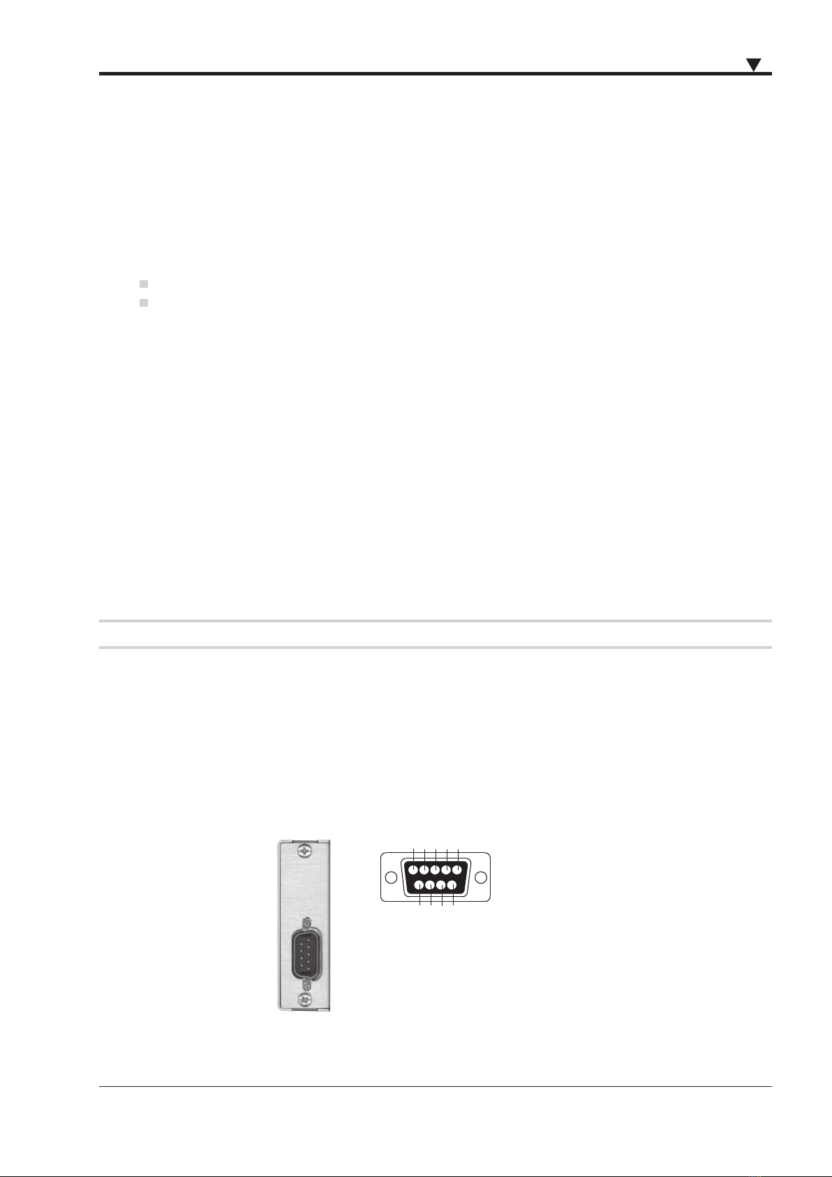
Connector D-SUB-9; DEWETRON bridge type pinout
Excitation current
Excitation current 1, 2, 4 mA; software programmable
Accuracy 0 to 200 µA: 0.02 % ±50 nA
200 µA to 5 mA: 0.02 % ±1 µA
Drift 15 ppm/°K
Compliance voltage 15 V
Source resistance >150 kΩ
Bandwidth (-3dB) 3 kHz
Filters 3 Hz, 10 Hz, 30 Hz, 100 Hz, 300 Hz, 1 kHz, 3 kHz
Filter characteristics Butterworth or Bessel, 2nd, 4th, 6th, 8th order programmable
Group delay 300 µs with highest lter
Typ. CMRR
50 Hz
1 kHz
3 kHz
0 to 100 mV range 100 mV to 5 V range Thermocouple input
125 105 160
120 100 135
115 95 130
Isolation 1 kVRMS
1)
Over voltage protection ±100 V between inputs (clamping voltage: 5 V @ TC input; 11 V @ Voltage input)
Output voltage ±5 V; 0 to 5V; (±10 V and 0 to 10 V with special DEWE-30)
Output resistance 22 Ω
Output current Max. 5 mA
Output protection Continuous short to ground
RS-485 interface Yes
RS-485 data output Yes
Supported TEDS chips DS2406, DS2430A, DS2431, DS2432, DS2433,DS28EC20
MSI support No
Power supply voltage ±9 VDC (±5 %)
Power consumption 1 W typical
1) Although the rated input voltage is 33 VRMS, 46,7 VPEAK or 70 VDC according to EN-61010-1 and EN-61010-2-30, the galvanic isolation for input, excitation and TEDS
has been tested with 1 kVRMS for 1 min.
= DAQP-MULTI support only
continued on page 78
450134 • DAQP/HSI/PAD Modules • Technical Reference Manual • Printing version 2.3.4 • November 18, 2020