Fagor CE6-20 Parts list manual

0
Instrucciones generales para instalación, uso y mantenimiento
COCINAS ELECTRICAS
Instructions générales pour l’instalation, l’utilisation et
l’entretien
FOURNEAUX ELECTRIQUES
General instructions for installation, use and maintenance
ELECTRIC RANGES
Allgemeine bedienungssanleitung für Installation, Gebrauch
und Wartung
ELEKTRO HERDE
Istruzioni generali per l’installazione, l’uso e la manutenzione
CUCINE ELETTRICHE
CE6-20
CE6-40
CE6-41
J036501

1
CE6-20
CE6-40
M: Control
P: Pilot
E: Hole for the cable to go through
M: Mando
P: Piloto
E: Orificio para pasar
cable manguera
M: Control
P: Pilot
E: Hole for the cable to go through
M: Mando
P: Piloto
E: Orificio para pasar cable manguera

2
CE6-41
M: Control
P: Pilot
C: Hole for the cable to go through
M: Mando
P: Piloto
C: Orificio para pasar cable manguera
Mth:Mando termostato Horno
Mrm:Mando resistencias horno

3
Fi
g
. 5
Fig. 2

4
Estimado cliente
Agradecemos la confianza que ha tenido con nuestra marca al adquirir un aparato de uso profesional.
Estamos plenamente convencidos de que a medida que pase el tiempo, quedará totalmente satisfecho de
su compra.
Tómese unos minutos de tiempo, acérquese con este manual al aparato y “manos a la obra”: las
informaciones gráficas de fácil comprensión sustituyen a las hojas llenas de texto.
No obstante, le aconsejamos estudie detenidamente este manual copilado por los jefes de cocina de
FAGOR, únicamente así podrá beneficiarse al máximo de las múltiples posibilidades y ventajas que le
brinda este aparato.
Conserve este manual cerca del aparato y en lugar siempre accesible.
Finalmente, le deseamos mucho éxito y gran satisfacción con su nueva cocina.
FAGOR
Indice
Instalación
Dimensiones generales y acometidas 1-2
Características técnicas 5
Emplazamiento y nivelación 7
Conexión eléctrica 7
Uso
Encendido del aparato 7
Mantenimiento
Mantenimiento 8
Recomendación de protección ambiental
Recomendación de protección ambiental 8

5
Cuadro Nº 2
Características técnicas(Tabla 1)
Potencias conmutadores(Tabla 2)
TENSIÓN
ALIMENTACIÓN SECCIÓN
MANGUERA FUSIBLE INT.
GENERAL DISPOSITIVO
DIFERENCIAL
230V 50-60Hz 2x1,5mm²+T 4A 30mA
POTENCIA ELÉCTRICA kW 0,1kW
MODELO CE6-20 CE6-40 CE6-41
Anchura 400 600 600
Profundidad 650 650 650
DIMENSIONES
EXTERNAS (mm) Altura 290 290 850
Anchura --- --- 450
Profundidad --- --- 400
DIMENSIONES
HORNO (mm) Altura --- --- 300
PESO NETO (Kgs.) 17 26 80
1.5 kW/h (mesa) - 1 1
PLACAS 2 kW/h (mesa) 2 3 3
1 kW/h (grill) - - 3
Nº DE RESISTENCIAS 1 kW/h (horno) - - 3
Secc. Manguera 4x1.5mm2+T 4x2,5mm2+T 4x4mm2+T
380...415V
3N Intensidad
Nonimal 9A 16A 24A
Secc. Manguera 2x2,5mm2+T 2x6mm2+T 2x16mm2+T
220...240V
1N Intensidad
Nonimal 18A 33A 59A
Secc. Manguera 3x2,5mm2+T 3x4mm2+T 3x6mm2+T
220V 3 Intensidad
Nonimal 15A 11A 36A
Secc. Manguera 3x1.5mm2+T 3x1,5mm2+T 3x4mm2+T
TENSION DE
ALIMENTACION
(50/60 Hz)
440V 3 Fusible int.
General 5A 12A 21A
POTENCIA TOTAL kW 4 7.5 13.5
POTENCIAS CORRESPONDIENTES A DISTINTAS POSICIONES DE CONMUTADORES DE MESA
PLACAS DE MESA 0 6 5 4 3 2 1
1,5 kW/h 0 W 1500 W 1125 W 750 W 375 W 250 W 150 W
2 kW/h 0 W 2000 W 1500 W 1000 W 500 W 330 W 200 W

6
Posiciones y temperaturas (aproximadas) del horno.(Tabla 3)
220-280 ºC 230-250 ºC
250-300 ºC 230-250 ºC
220-250 ºC 210-240 ºC
200-220 ºC 200-230 ºC
220-250 ºC 190-210 ºC
1
2
3
4
5
6
7
8
90 ºC
120 ºC
170 ºC
200 ºC
230 ºC
260 ºC
280 ºC
315 ºC

7
1.- INSTALACIÓN
Emplazamiento y nivelación
El emplazamiento y la instalación tanto eléctrica como de gas, debe realizarse siempre por un TÉCNICO
AUTORIZADO, respetando las normas de cada país.
•Es conveniente instalar una campana extractora para el buen funcionamiento.
•Ubicar el aparato en un local bien ventilado.
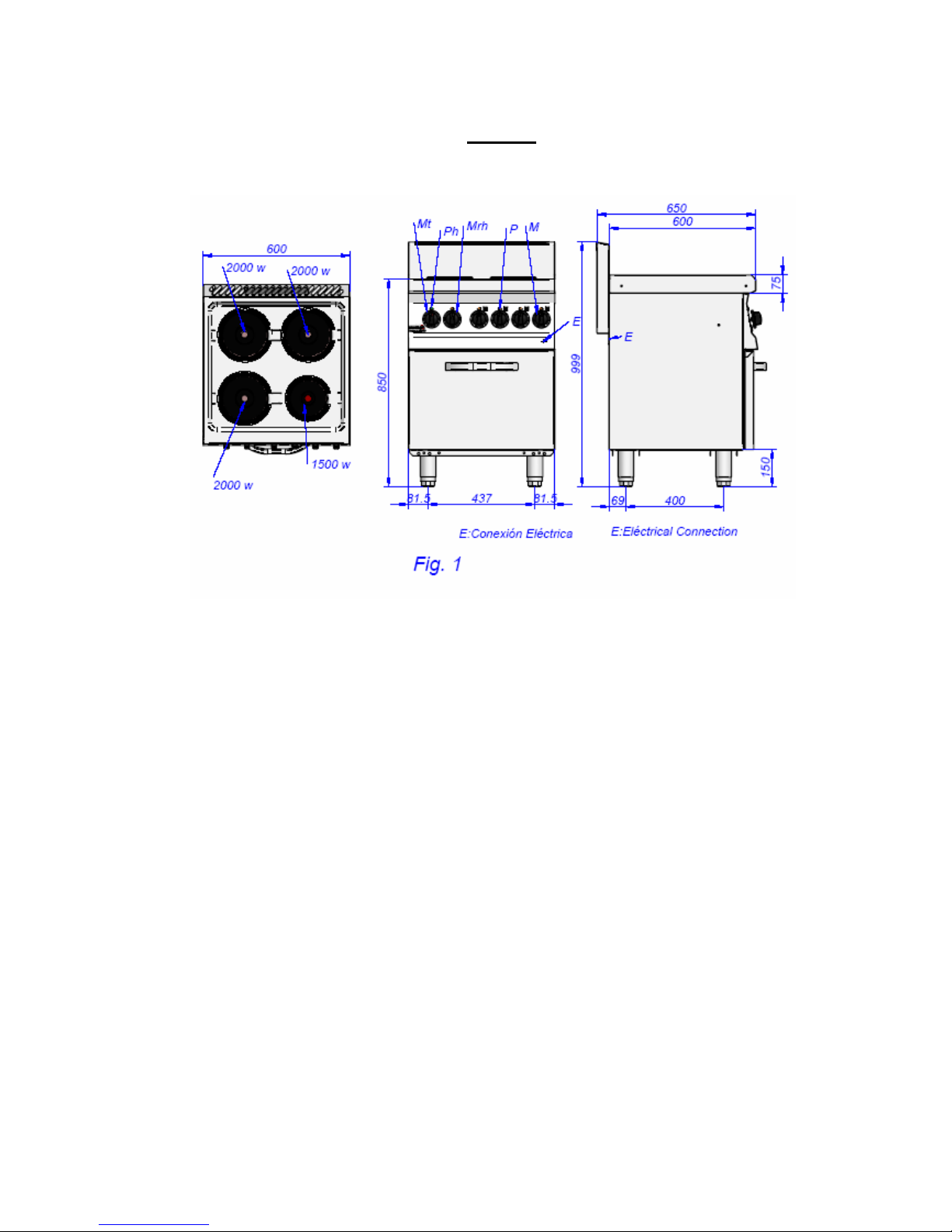
•Nivelar y regular la altura del aparato.(Fig. 1) y .(Fig. 1A)
Conexión eléctrica
La conexión eléctrica del aparato debe hacerse siempre por un TÉCNICO AUTORIZADO.
Se deberá tener en cuenta las normas legales vigentes en cada país en materia de conexiones a la red
eléctrica.
Verificar que la tensión de la red corresponde a la que se indica en la placa de características.
Para la conexión emplear cable manguera de polycloropreno u otro material de similares características
(H05RN-F).
Próximo al aparato debe instalarse un dispositivo interruptor para todas las fases, con un mínimo de 3mm
de apertura entre contactos. Este interruptor irá provisto de fusibles.
Es obligatorio conectar a tierra el aparato, El fabricante no se hace responsable de posibles daños
originados por el incumplimiento de este requisito
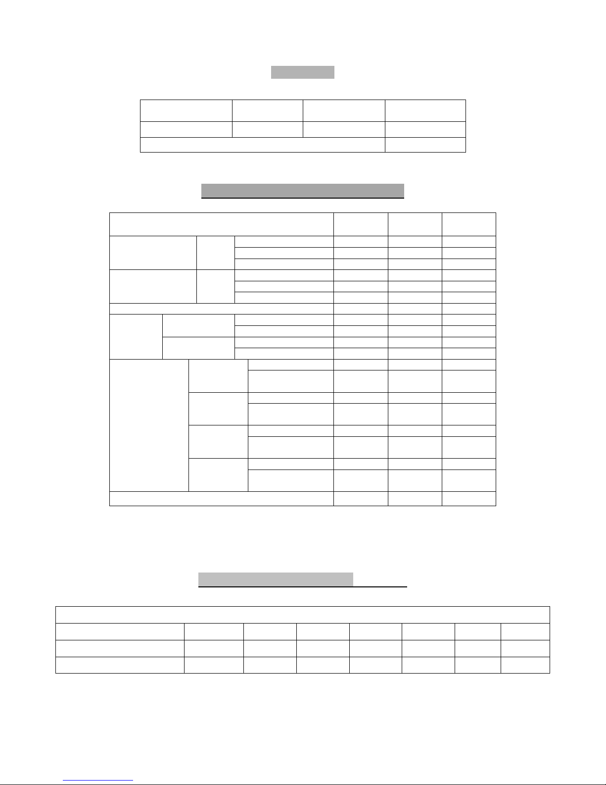
La sección de cable manguera y el valor de los fusibles a instalar en el interruptor general, queda reflejado
en el cuadro Nº 2.
MUY IMPORTANTE: Antes de colocar la tapa de cuadro eléctrico fijar la manguera de alimentación
eléctrica fuertemente al prensa estopas.
Cuando se instalen varios aparatos en línea, deberán ser conectados entre sí a tierra, por el punto
destinado a tal fin, que se encuentra ubicado en la base de la cocina, zona posterior.
2.-USO
Encendido del aparato
Encendido de las placas de mesa (1,5 y 2 kW/h)
a) Accionar el interruptor general de corriente eléctrica situado en el exterior del aparato.
b) Girar el mando “M” (Fig. 2) del conmutador correspondiente a la placa que se desea encender,
hasta la posición o potencia elegida, en ese momento se encenderá el piloto “P1” (Fig. 2)
indicándonos que la placa y la potencia elegida está funcionando.
Apagado de las placas de mesa
a) Si desea apagar la placa, girar el mando “M” hasta la posición “OFF” (Fig. 2). En esa posición
el piloto “P1” se apagará.

8
Encendido del horno
a) Una vez decidido el sistema de calentamiento (Fig. 4) girar el mando “MHG” hasta la posición
elegida. En ese momento se encenderá el piloto “P2” (color verde) indicándonos que el horno
está preparado para funcionar.
b) Seleccionar la temperatura según la tabla nº 3, girando el mando “MTH” a la posición elegida,
en ese momento se encenderá el piloto “P3” (color ámbar), indicándonos que las resistencias
están funcionando.
c) En el instante que el horno alcance la temperatura seleccionada las resistencias dejarán de
actuar (por medio del termostato) y el piloto “AMBAR” se apagará.
Asimismo, en cuanto baje del valor seleccionado, las resistencias comenzarán a actuar,
encendiéndose el piloto “AMBAR”.
Apagado del horno
a) Llevar los dos mandos “MTH” y “MHG” a la posición “OFF”. Apagándose los pilotos “AMBAR”
y “VERDE”.
Se recomienda no tener las placas encendidas en vacío (sin carga, cazuelas, sartenes etc.) ya que
se estropean.
3.-MANTENIMIENTO
Limpieza diaria
Para que el aparato se mantenga como el primer día, es conveniente seguir las siguientes instrucciones:
a) No utilizar detergentes arenosos y abrasivos.
b) No utilizar manguera de agua para la limpieza del aparato.
La superficie interior de los hornos debe limpiarse diariamente después de ser utilizada, para ello se
aplicará alguno de los productos desengrasantes específicos del mercado.
Indicaciones para el uso del horno
a) Antes de usar el horno se recomienda limpiar su interior con un paño impregnado de agua
jabonosa, para evitar malos olores en su primer servicio.
b) Se pueden preparar al mismo tiempo varias bandejas de asado, siendo el resultado satisfactorio
en todas ellas, debido al sistema calefactor utilizado.
Componentes funcionales
1. Componentes de mesa “M”.
2. Conmutador de horno “MHE”.
3. Termostato de horno “MTH”.
4. Regleta de conexiones “R”.
NOTA IMPORTANTE:

9
La sustitución de cualquier componente funcional que pueda afectar a la seguridad deberá ser efectuada
por un TÉCNICO AUTORIZADO.
Antes de realizar cualquier cambio, se asegurará que el interruptor general está desconectado.
4.-RECOMENDACIÓN DE PROTECCIÓN AMBIENTAL
Al terminar su vida útil, este producto no debe tirarse en un
contenedor de basuras estándar, sino que debe dejarse en un punto
de recogida de deshechos eléctricos y equipamiento electrónico para
ser reciclado.
Esto viene confirmado por el símbolo que se encuentra en el
producto, manual del usuario o embalaje.
Dependiendo de sus características, los materiales pueden reciclarse.
Mediante el reciclaje y otras formas de procesamiento de los
deshechos eléctricos y el equipamiento electrónico puedes contribuir
de forma significativa a ayuda a proteger el medio ambiente.
Contacta con las autoridades locales para más información sobre el
punto de recogida más cercano.
Para preservar el medio ambiente, al final de la vida útil de su
producto, deposítelo en los lugares destinado a ello de acuerdo con la
legislación vigente.
Este aparato es únicamente de uso profesional y debe
ser utilizado por personal cualificado.

10
Cher client
Nous vous remercions de la confiance dont vous faites preuve envers notre marque en achetant un
appareil à usage professionnel. Nous sommes entièrement convaincus qu'au fil du temps, vous serez
pleinement satisfait de votre achat.
Prenez quelques minutes, approchez-vous de l'appareil muni de ce manuel et "au travail !": les pages
remplies de texte sont remplacées par des informations graphiques faciles à comprendre.
Cependant, nous vous conseillons d'étudier attentivement ce manuel compilé par les chefs cuisiniers de
FAGOR. Ce n'est qu'ainsi qu'il vous sera possible de tirer le plus grand parti des multiples possibilités et
avantages que vous offre cet appareil.
Conservez ce manuel près de l'appareil et toujours à portée de main.
Nous vous souhaitons d’excellents résultats et de grandes satisfactions avec votre nouvelle fourneaux.
FAGOR
Sommaire
Installation
Dimensions générales et branchements 1-3
Caractéristiques techniques 11
Mise en place et nivellement 12
Raccordement électrique 12
Utilisation
Allumage de l’appareil 13
Entretien
Entretien 13
Recommandation de protection de l’environnement
Recommandation de protection de l’environnement 14

11
Tableau Nº 2
TENSION
ALIMENTATION SECTION
CÂBLE FUSIBLE INT.
GÉNÉRAL DISPOSITIF
DIFFÉRENTIEL
230V 50-60Hz 2x1,5mm²+T 4A 30mA
PUISSANCE ÉLECTRIQUE kW 0,1kW
Caractéristiques techniques
MODÈLE CE6-20 CE6-40 CE6-41
Largeur 400 600 600
Profondeur 650 650 650
DIMENSIONS
EXTÉRIEURES (mm) Hauteur 290 290 850
Largeur --- --- 450
Profondeur --- --- 400
DIMENSIONS
FOUR (mm) Hauteur --- --- 300
POIDS NET (kg.) 17 26 80
1.5 kW/h (table) - 1 1
PLAQUES 2 kW/h (table) 2 3 3
1 kW/h (grill) - - 3
Nº DE RÉSISTANCES 1 kW/h (tour) - - 3
Sect. câble 4x1.5mm2+T 4x2,5mm2+T 4x4mm2+T
380...415V 3N Fusible int.
General 9A 16A 24A
Sect. câble 2x2,5mm2+T 2x6mm2+T 2x16mm2+T
220...240V 1N Fusible int.
Général 18A 33A 59A
Sect. câble 3x6mm2+T 3x10mm2+T 3x16mm2+T
220V 3 Fusible int.
Général 15A 21A 36A
Sect. câble 3x1.5mm2+T 3x1,5mm2+T 3x4mm2+T
TENSION
ALIMENTATION
(50/60 Hz)
440V 3 Fusible int.
Général 5A 12A 21A
PUISSANCE TOTALE kW 4 7.5 13.5
PUISSANCES CORRESPONDANT À DIFFÉRENTES POSITIONS DE COMMUTATEURS DE TABLE
PLAQUES DE TABLE 0 6 5 4 3 2 1
1,5 kW/h 0 W 1500 W 1125 W 750 W 375 W 250 W 150 W
2 kW/h 0 W 2000 W 1500 W 1000 W 500 W 330 W 200 W

12
Positions et températures (approximatives) du four (Tableau nº3)
220-280 ºC 230-250 ºC
250-300 ºC 230-250 ºC
220-250 ºC 210-240 ºC
200-220 ºC 200-230 ºC
220-250 ºC 190-210 ºC
1
2
3
4
5
6
7
8
90 ºC
120 ºC
170 ºC
200 ºC
230 ºC
260 ºC
280 ºC
315 ºC
1.-INSTALACION
Mise en place et nivellement
∗La mise en place ainsi que l'installation électrique et de gaz doivent toujours être effectuées par un
TECHNICIEN AGRÉÉ, conformément aux normes de chaque pays.
∗Il convient d’installer une hotte aspirante pour un fonctionnement correct.
∗Installez l'appareil dans un local bien aéré.
∗Niveler et régler la hauteur de l’appareil. (Fig. 1) et (Fig. 1A)
Branchement électrique
Le branchement électrique de l’appareil doit toujours être fait par un TECHNICIEN AGRÉÉ.
Il faudra tenir compte des normes légales en vigueur dans chaque pays en matière de raccordements au
réseau électrique.
Vérifiez que la tension du réseau correspond à celle qui est indiquée sur la plaque signalétique.
Pour le branchement, utiliser un câble de conduite en polychloroprène ou un autre matériel ayant des
caractéristiques similaires (H05RN-F).
Placez, sur la prise réseau, un interrupteur général pourvu de fusibles, indépendant de l’appareil, et dont
la distance entre contacts est égale ou supérieure à 3mm.
Il est obligatoire de connecter l’appareil à une prise de terre. Le fabricant n’est pas responsable des
dommages qui pourraient être causés par le manque de suivi de cette exigence.
La section de câble conduite et la valeur des fusibles à installer sur le interrupteur général, sont indiquées
sur le tableau Nº 2.
TRÈS IMPORTANT : Avant de remettre en place le couvercle du boîtier électrique, fixez solidement le
câble d'alimentation électrique au presse-étoupes.
En cas d’installation de plusieurs appareils en ligne, ceux-ci devront être connectés entre eux et à la prise
de terre, par le point prévu pour cela, et qui se trouve placé sur la base de l’appareil, dans la zone arrière.

13
2.-UTILIZACIÓN
Allumage de l’appareil
Allumer les plaques de table (1,5 y 2 kW/h)
c) Actionner l’interrupteur général de courant électrique situé à l’extérieur de l’appareil.
d) Tourner le bouton “M” (Fig. 2) du commutateur correspondant à la plaque que l’on souhaite
allumer, jusqu’à la position ou la puissance choisie, et la veilleuse “P1” (Fig. 2) s’allumera, nous
indiquant que la plaque fonctionne à la puissance choisie.
Éteindre les plaques de table
b) Si vous souhaitez éteindre la plaque, tourner le bouton “M” jusqu’à la position “OFF” (Fig. 2).
Dans cette position, la veilleuse “P1” s’éteindra.
Allumage du four
d) Après avoir choisi le système de chauffage (Fig. 4) tourner la commande “MHG” jusqu’à la
position choisie. On allumera alors le voyant “P2” (vert) qui nous indiquera que le four est prêt
à fonctionner
e) Sélectionner la température en fonction du tableau nº 3, en tournant la commande “MTH” sur
la position choisie, et le voyant “P3” (orange) s’allumera, nous indiquant que les résistances
fonctionnent.
f)Lorsque le four atteint la température choisie, les résistances arrêtent de fonctionner (par
l’intermédiaire du thermostat) et le voyant “ORANGE” s’éteint.
De même, quand la valeur sélectionnée diminue, les résistances commencent à agir et le
voyant “ORANGE” s’allume.
Eteindre le four
b) Amener les deux commandes “MTH” et “MHG” sur la position “OFF”. Les voyants “ORANGE”
et “VERT” s’éteignent.
3.-ENTRETIEN
Nettoyage quotidien
Pour que l’appareil se maintienne comme au premier jour dans les conditions de fonctionnement et avec
les rendements corrects, il convient de suivre les instructions suivantes:
c) Ne pas utiliser de détergents sablonneux et abrasifs pour le nettoyer.
d) Ne pas utiliser de jet d'eau pour le nettoyer.
La surface des fours doit être nettoyée tous les jours après usage, en appliquant l’un des produits de
dégraissage spécifiques existant sur le marché.
Indications pour l’utilisation du four
c) Avant d’utiliser le four, il est recommandé d’en nettoyer l’intérieur avec un chiffon imprégné d’eau
savonneuse, afin d’éviter les mauvaises odeurs lors de la mise en service.

14
d) On peut préparer plusieurs grilles de cuisson en même temps, le système de chauffage utilisé
permettra un résultat satisfaisant avec toutes celles-ci.
Composants Fonctionnels
5. Composants de table “M”.
6. Commutateur de four “MHE”.
7. Thermostat du four “MTH”.
8. Réglette de connexions “R”.
NOTE IMPORTANT:
Le remplacement de tout composant fonctionnel pouvant affecter la sécurité devra être effectué par un
TECHNICIEN AGRÉÉ.
Avant d’effectuer un changement quelconque, s’assurer que l’interrupteur général est déconnecté.
4.-RECOMMANDATION DE PROTECTION DE L’ENVIRONNEMENT
En fin de vie utile, ce produit ne doit pas être jeté dans un conteneur
d’ordures standard, mais il doit être déposé dans un point de récupération
d’appareils électriques et d’équipements électroniques afin d’être recyclé.
Ce fait est confirmé par un symbole qui se trouve sur le produit, le manuel
d’utilisation ou l’emballage.
En fonction de leurs caractéristiques, les matériaux peuvent être recyclés.
Le recyclage et les autres formes de gestion des résidus électriques et des
équipements électroniques, vous permettent de grandement contribuer à
aider à protéger l’environnement.
Contactez les autorités locales pour plus d’informations quant au point de
récupération le plus proche.
Afin de préserver l’environnement, en fin de vie utile de votre produit, veuillez
le déposer dans les lieux prévus à cet effet, conformément à la législation en
vigueur
Cet appareil est exclusivement destiné à l'usage
professionnel et doit être utilisé par du
personnel qualifié.

15
Dear costumer
We would like to thank you for the confidence you have shown in our product on purchasing a professional
appliance. We are totally convinced that in time you will be completely satisfied with your purchase.
Take a few minutes of your time and get to know the appliance with this instructions manual and "down to
work": the easy to understand graphical information replaces pages full of writing.
Nevertheless, we recommend you thoroughly read this manual compiled by FAGOR's kitchen supervisors,
in order to benefit to the maximum from the multiple possibilities and advantages this appliance offers you.
Keep this manual near to the appliance and at all times in an accessible place.
Lastly, we wish you success and hope that you will be fully satisfied with your new range.
FAGOR
Index
Installation
General and connection dimensions 1-3
Technical specifications 16
Positioning and levelling 17
Electrical connection 17
Use
Turning the appliance on 18
Maintenance
Maintenance 19
Environmental protection recommendation
Environmental protection recommendation 19

16
Diagram no. 2
Technical specifications(Tabla 1)
Table no. 2)
SUPPLY
VOLTAGE CABLE
SECTION POWER SWITCH
FUSE DIFFERENTIAL
DEVICE
230 V 50-60 Hz 2 x 1.5 mm²+T 4A 30 mA
ELECTRICAL OUTPUT kW 0.1 kW
MODEL CE6-20 CE6-40 CE6-41
Width 400 600 600
Depth 650 650 650
EXTERNAL
DIMENSIONS (mm) Height 290 290 850
Width --- --- 450
Depth --- --- 400
OVEN
DIMENSIONS (mm) Height --- --- 300
NET WEIGHT (kg) 17 26 80
1.5 kW/h (table) - 1 1
PLATES 2 kW/h (table) 2 3 3
1 kW/h (grill) - - 3
NO. OF RESISTORS 1 kW/h (oven) - - 3
Cable Sect. 4 x 1.5 mm2+T 4 x 2,5 mm2+T 4 x 4 mm2+T
380...415V 3N Power Switch
Fuse 9A 16A 24A
Cable Sect. 2 x 2,5 mm2+T 2x 6 mm2+T 2 x 16 mm2+T
220...240V 1N Power Switch
Fuse 18A 33A 59A
Cable Sect. 3 x 2,5 mm2+T 3 x 4 mm2+T 3 x 6 mm2+T
220V 3 Power Switch
Fuse 15A 21A 36A
Cable section 3 x 1.5 mm2+T 3 x 1,5mm2+T 3x 4 mm2+T
SUPPLY
VOLTAGE
(50/60 Hz)
440V 3 Power Switch
Fuse 5A 12A 21A
TOTAL POWER kW 4 7.5 13.5
POWERS CORRESPONDING TO DIFFERENT TABLE SWITCH POSITIONS
TABLE PLATES 0 6 5 4 3 2 1
1,5 kW/h 0 W 1500 W 1125 W 750 W 375 W 250 W 150 W
2 kW/h 0 W 2000 W 1500 W 1000 W 500 W 330 W 200 W

17
Oven position and temperature (approximate) table (Table no. 3)
220-280 ºC 230-250 ºC
250-300 ºC 230-250 ºC
220-250 ºC 210-240 ºC
200-220 ºC 200-230 ºC
220-250 ºC 190-210 ºC
1
2
3
4
5
6
7
8
90 ºC
120 ºC
170 ºC
200 ºC
230 ºC
260 ºC
280 ºC
315 ºC
1.-INSTALLATION
Positioning and levelling
The positioning and electrical and gas installation should always be carried out by an AUTHORISED
TECHNICIAN, observing the standards of each country.
•It is advisable to install an extraction hood for the optimum operation of the appliance.
•Place the appliance in a well-ventilated place.
•Level and adjust the height of the appliance. (Fig. 1) and (Fig. 1A)
Electrical connection
An AUTHORISED TECHNICIAN should always carry out the appliance’s electrical connection.
The legal standards in force in each country on connections to the mains should be taken into account.
Check that the mains voltage corresponds to that indicated on the nameplate.
Use cable sleeves made out of polychloroprene or other similar materials (H05RN-F), for the connection.
A switch device should be installed next to the appliance for all the phases, with a gap of a minimum of 3
mm between contacts. This switch will be equipped with fuses.
It is obligatory to earth the appliance. The manufacturer takes no responsibility if this requirement is not
fulfilled.
Electrical connection
An AUTHORISED TECHNICIAN should always carry out the appliance’s electrical connection.
The legal standards in force in each country on connections to the mains should be taken into account.

18
Check that the mains voltage corresponds to that indicated on the nameplate.
Use cable sleeves made out of polychloroprene or other similar materials (H05RN-F), for the connection.
A switch device should be installed next to the appliance for all the phases, with a gap of a minimum of 3
mm between contacts. This switch will be equipped with fuses.
It is obligatory to earth the appliance. The manufacturer takes no responsibility if this requirement is not
fulfilled.
The section of cable sleeve and the rating of the fuses to be installed in the power switch are indicated in
diagram no. 2.
VERY IMPORTANT: Before putting the switchboard top on, fasten the electric supply cable tightly to the
stuffing box.
When several appliances are installed in series, they should be earthed to each other using the point
assigned for this purpose, located in the appliance's base, at the back.
2.-USE
Turning the appliance on
Turning the table plates on
e) Press the power switch situated on the outside of the appliance.
f) Turn the “M” control (Fig. 2) of the switch corresponding to the plate you want to turn on, to the
chosen position or power, and then the “P1” pilot light will turn of (Fig. 2) telling us that the
chosen plate and power are working.
Turning the table plates off
c) If you want to turn the plate off, turn the “M” control to the “OFF” position (Fig. 2). The burner
will turn off in this position.
Turning the oven on
g) Once the heating system has been decided upon (Fig. 4), turn the “MHG” control to the
desired position. The pilot “P2” (green) will then turn on, indicating that the oven is ready for
operation.
h) Select the temperature according to table no. 3, turning the “MTH” control to the chosen
position. Pilot “P3” (amber) will turn on indicating that the resistors are working.
i) When the oven reaches the selected temperature, the resistors stop working (by means of the
thermostat) and the “AMBER” pilot will turn off.
Additionally, as soon as the selected value lowers, the resistors will start to work and the
“AMBER” pilot will turn on.
Turning the oven off
c) Turn the “MTH” and “MHG” controls to the “OFF” position. The “AMBAR” and “VERDE” pilot
lights turn off.

19
3.-MAITENANCE
Maintenance
Daily cleaning
In order for the appliance to work as new, it is advisable to follow the following instructions:
e) Do not use gritty and abrasive detergents.
f) Do not use a water hose to clean the appliance.
The surface of the ovens must be cleaned daily after use, with any specific marketed degreasing product.
Indications for oven use
e) Before using the oven, it is advisable to clean the inside with a cloth soaked in soapy water, to
prevent bad smells during its first use.
f) Several roasting trays can be prepared at the same time, with good results in all of them, due to
the heating system used.
Functional components
9. Table components “M”.
10. Oven switch “MHE”.
11. Oven thermostat “MTH”.
12. Terminal strip “R”.
IMPORTANT NOTE:
The replacement of any functional component that can affect the safety of the appliance must be carried
out by an AUTHORISED TECHNICIAN.
Before making any changes, ensure that the power switch is off.
4.-ENVIRONMENTAL PROTECTION RECOMMENDATION
On ending its useful life, this product must not be thrown away in a standard
rubbish bin, but must be left in an electrical waste and electronic equipment
collection point for recycling.
This is confirmed by the symbol on the product, user manual, or packaging.
Depending on the symbol, the materials can be recycled. By recycling and
other ways of processing electrical waste and electronic equipment, you can
significantly contribute to protecting the environment.
Contact your local authorities for more information of the nearest collection
point.
To conserve the environment at the end of the useful life of your product.
Leave it in the appropriate places in accordance with the current legislation.
This appliance is only for professional usage
and must be used by qualified personnel.
This manual suits for next models
2
Table of contents
Languages:
Other Fagor Range manuals