Fairchild DA415/8 User manual

www.SteamPoweredRadio.Com
FAIRCHILD
DISTRIBUTION
AMPLIFIER
-
MODEL
DA415/8
IBDA415/8-171
INSTRUCTION
MANUAL
-
CHILD
SOUND
EQUIPMENT
CORPORATION
, 10-40 45th Avenue, Long Island City, N.Y. 11101, 212 784-6163

www.SteamPoweredRadio.Com
-

www.SteamPoweredRadio.Com
-
-
FAIRCHILD
DA415/8 DISTRIBUTION
AMPLIFIER
GENERAL
The
MODEL
DA415/8
Distribution
Amplifier
,
is
designed
to
provide
a means
of
sending
signals
from
one
or
more
sources
into
8
separate
lines
with
minimum amount
of
interaction
between
channels,
minimum
distortion
of
the
distributed
signal
and
flat
frequency
response.
The DA415-8
consists
of
8
separate
isolation
amplifiers.
Input
and
output
of
each
amplifier
is
accessible
individually
through
a
24
pin
blue
ribbon
connector
in
the
back
of
the
chassis.
This
provides
for
a
variety
of
interconnections
that
can
be
made
with
the
8
isolation
amplifiers.
High
in-
put
impedance
of
each
amplifier
allows
connection
to
high
impedance
sources.
A
self-contained
power
supply
(692PS.24)
excludes
the
use
of
any
audio
transformers
inside
the
amplifier
enclosure
since
hum
fields
emanating
from
the
power
transformers
could
be
picked
up
by
the
best
shielded
audio
transformers.
The DA415/8
output
circuits
are
designed
to
be
used
with
reactive
loads
driving
conventional
600
ohm
lines.
Maximum
output
handling
capability
of
each
amplifier
is
designed
to
match
the
performance
of
the
transformers
normally
used
in
transmission
lines,
as
well
as
power
limitations
of
telephone
lines.
Unity
voltage
gain
of
the
DA415/8
enables
dire
ct
connections
of
the
input
to
high
level
sources
such
as
console
outputs,
outputs
of
tape
machines,
mixers
or
telephone
lines.
Circuit
of
the
amplifiers
in
the
DA415/8
is
a
Class
A
emitter
follower.
Input
impedance
at
the
first
stage
is
lOOK
ohms. The
output
stage
has
very
low
output
impedance
designed
to
work
into
resistive
or
inductive
load.
This
output
impedance
is
important
when
feeding
telephone
lines
through
a
transformer
so
that,
in
effect,
the
telco
line
impedance
is
bridging
the
output
of
the
DA415/8
and
chances
of
in
t
eraction
of
two
transformers
is
eliminated
through
a
high
damping
factor
offered
by
the
amplifier
output.
This
eliminates
the
need
for
an
isolation
pad
normally
used
with
amplifiers
having
a
low
damping
effect
(matching
output
impedance).
The
power
supply
driving
the
DA415/8
is
packaged
on a
separate
plug-in
card,
capable
of
delivering
,.
the
needed
power
to
drive
all
8
amplifiers.
Its
active
filter
and
voltage
regulator
circuits
feature
overload
and
short
circuit
protection
as
well
as
very
low
ripple
voltage,
important
for
good
signal-to-noise
ratio.

www.SteamPoweredRadio.Com
oo
,,.c,;.
.c..li
'
OWo
.
wo.-i
,c.
TO
..-,.u.-in.
TOL.l:IIIANc;:I(•
•
UNL.11:••
OTHU'1¥1111:
•Nc;:
1
11"
1
11:D
Dll:
c;:
. 0 1
..
1 , t
l"llAc;:
.
01
...
, :t
ANQUL.Aft
DIN•
. t
IJ7)1JIC
60/V
Fl
II/MP
GAIN
DftlL,L,
,
~UNCH
, c;:C)flll[Mll:lllc;:IAL. ST
OCK
1121:
■
AND
MANU,,Ac;:TUftt:111
'
TOL.UIAH
c;:
11:
■
Altll:
NOT
INc;:L.UD.lD
.
8
'"
C
ONTROL
IOOK
lo
692
PS
-
24
BRC-1
II
Z4
23
+Z4
11,16,15,14
22,21
,2
0,
19
69
,.
2
3,;
'9'
0
692
HL
IC
·2
z,
7,
14
,
19
-
BRC
- I
1,15
4,IS
6
,Z0
9,Z0
2,15
5,15
1,
20
10,20
I
I
l1LJC-I
--
-----------i
4 2
6
16
,14
12
21,19
18
I _
___________
!
~--
----------1
I 412 I
1------------<
;
>--
--
--------<
-
I
I
9 , 7
16, 14
Zl,19
tS
12
18
I _
___
________
I
>ILIC-2
ISSUt:
BRC-1
13,
15
16,
IS
18,ZO
21,20
14,
15
17,15
19,Z0
Z2,20
FOR
PA
4 ! S - 8
SCHEMATIC DIAGRAM
DISTRIBUTION
AMPLIFIER
FAIRCHILD
RECORDING
EQUIPMENT
CORPORATION
10
-
4.0
4.!:I
AV
E
••
L .
I.
C . I , N . Y .

www.SteamPoweredRadio.Com
.,
..
The DA415/8
circuits
are
packaged
into
a
space
3n wide
by
5y4n
high
and
10"
d
eep
. The
amplifier
circuit
s
are
assembled
on
two
plug-in
cards
with
4
amplifiers
on
each
card.
Since
expected
reliability
of
the
circuits
is
very
high,
access
to
these
plug
-in
cards
was
not
designed
for
instantaneous
card
replacement,
but
rather
through
the
removal
of
the
chassis
cover,
Connections
of
the
amplifiers
are
made
through
a
blue
rib-
bon
connector
i n
the
back
of
the
cha
s
sis.
Inputs
may
be
strapped
for
lx8
distribution,
or
used
individually,
The
front
of
the
DA415/8
includes
a
gain
control
to
be
used
in
the
case
of
co=on
input
to
all
amplifiers.
CONNtlJTIONS
See
schematic
diagrams
provided,
A
TT
ACHMEN'fS
~chematic
diagram
DA415/8
~7158
Amplifier
card
schematic
B96661
Power
Supply
card
schematic
B96857
GAIN
RESPONSE
DISTORTION
NO
ISE
SP..t,CIFICATIONS
NUMB~
OF
AMPLIFIERS
INPUT
IMPEDA
NC
,1:;
MINIMUI-
1
INPUT
I
MP
.t;
DANC
E
(all
amplifiers
inputs
paral-
lelled)
OUTPU
'f
IMPEDANCE
RECOl"IMENDED
LOAD
IMP
E
DANCE
POWER
CONSUMPTION
MAX.
OUTPUT
HANDLING
CAPABILITY
DIMENSIONS
WEIGH
T
WARRAN
TY
POLICY
Unity
+l
db
from
20
to
20k:Hz
Less
than
0,3%
85db
below
+4
dbm
level
8
lOOK
each
amplifier
12K ohms
10
ohms
600
ohms
or
higher
-
re-
sistive
or
reactive
5
watts
+15
dbm
3V2"x5V4"x10"D
4
lbs
-
See
standard
warranty
policy
attached
to
~d
formin
g
part
of
this
manual.
To
validate
warranty,
complete
and
return
the
warranty
registration
card
included.
If
there
is
any
question
on
this
or
any
other
FAIRCHILD
professional
product,
please
do
not
hesitate
to
con
ta
ct
the
factory.
-

www.SteamPoweredRadio.Com
4'-.&
owa
•
wo•.:
TO
,.,ou•cL
oac
.
on•L
*
uo,i1o.c••
O
THir••••ir
•-
c:
,,.1,ro
4NG
U
UUI
0 1
MS
.
*
4,9,16,21
INPUT
2,7
,
13,14,19
GND
20
+
~
~z
IN
(
~~
19 -
15
+~
V
IN(l3,::
13,14
-
IN(
l
:~
~z
IN(
;
~~
~>
I
o•tlo.lo..
,-uN
C:
H .
C:ONMC•
C:1
4'-.
STOCK
■
1%CS
4N
O
lll4NU,-4
C:
TU•l•S
•
TO
!o.&•4N
C:
t:S
.....
N
OT
IN C
!o.
U
oiro
.
R6
-J_.,
C3
IOK
+
10
/16'
~
::
) OUT
~
:~.
14
) OUT
~
~
J
OUT
~
~
J
OUT
--
8-96661
ISSUE:
RIO
I.
4/11/69
30
+
24V
VVv---0
3,8,15,20
C5
T
5/25V
02
-
2N3569
-
+
j
6
f
+
I(
0 OUTPUT 1,6,12,18
C4
100/25V
COMMON
2,7,13,14,19
NOTES
:
I.
ALL
RESISTORS
ARE
IN
OHMS
a
l/4W
UNLESS
OTHERWISE SPECIFIED.
2.
ALL
CAPACITORS
IN
MFD UNLESS OTHERWISE
SPECIFIED.
I
1°SCHEMA.TIC
DIAGRAM
AMPLIFIER
....
~
..~,~
CARD
-
DA415/8
FAIRCHILD
RECORDING
EQUIPMENT
CORPORATION
·-·-
G-,,....
•<~•·
is-96661

www.SteamPoweredRadio.Com
DO
°"OT
ICALI.
DWQ
,
WOltK
TO
l'IQUltlU
,
TOLl:
ltAN
Cill
·
U°"L!II
OT
...
llltWllll
l~llCll'II.D
D1t1
1L
1
~ .•
:u:::
· M
CAON-:
M
l':::!:~
,a
TOLl.
ltA
...
CI.I
Altl.
NOT
l
°"
C':_ _ _
_______
_J
Tl
I
2N3766
WITH
HEAT
SINK
-
Cl
"1+2000
/
50V
01
't"
T
·
<'
NI
2125V
I I I
27K
\I+
RECTIFIER
VARO,.VS247
R2 i
NOTES
:
4.
7K
C4
2/25V
I.
UNLESS
OTHERWISE
SPECIFIED
ALL
RESISTORS ARE IN OHMS, 1/4
W.
ALL
CAPACITORS ARE IN MFD.
II RESISTOR
TO
BE
SELECTED.
02
2N3638
*
DI
F2
I
R3
*
/
i
02
IN96
~2
0gg/25V
+
I +
6857
I-
RI
B R2 WERE
22K
B
IK RESP. C5
WAS
.
12
.-
7/8170
S.K.
692-PS-24
SCHEMATIC
DIAGRAM
FAIRCHILD
RE
CORD
I
NG
EQUIPMENT
COR
PORATI
ON
J
O.AO
A5
A V E
..
L.
I.
C . 1, N . Y .
·-··
··6'?l"
r-.1
18-968.
57

www.SteamPoweredRadio.Com
TY'P't
INTEGRA
ll
PC
BOARD
MOUNTING DIMENSIONS
00000
00000
--c:::J--
--c::}-
1==11==1
--c:::>--
--c::r--
t=J~
--c:::>--
--c::r--
l=IBJl=i
0 0
0
--c:::r---
-----c:::J-
i=1§]
l=j§]
--c::::J--
--c:::r---
~l=l]
~
0
3..!
16
·--
!,
I
!.I
z.
3
____
......
n_._
__
......
o_._.o__._
__
_.o__,__~
l.___
__
ic,_r-_-_z_n_:::a_-_>_""
__
~I !
rATT
HEIGHT
f
tA'1
HE16Hr
k
~
C\
Io
ol
,b
J_I
ic,
,..
-z n
::a
-
,.
""
I
-1
-
-
5W/TCH
CARO
,._MP
ATT~NIIATOR
CARD
A-96297
Other Fairchild Amplifier manuals

Fairchild
Fairchild DA415/8 User manual

Fairchild
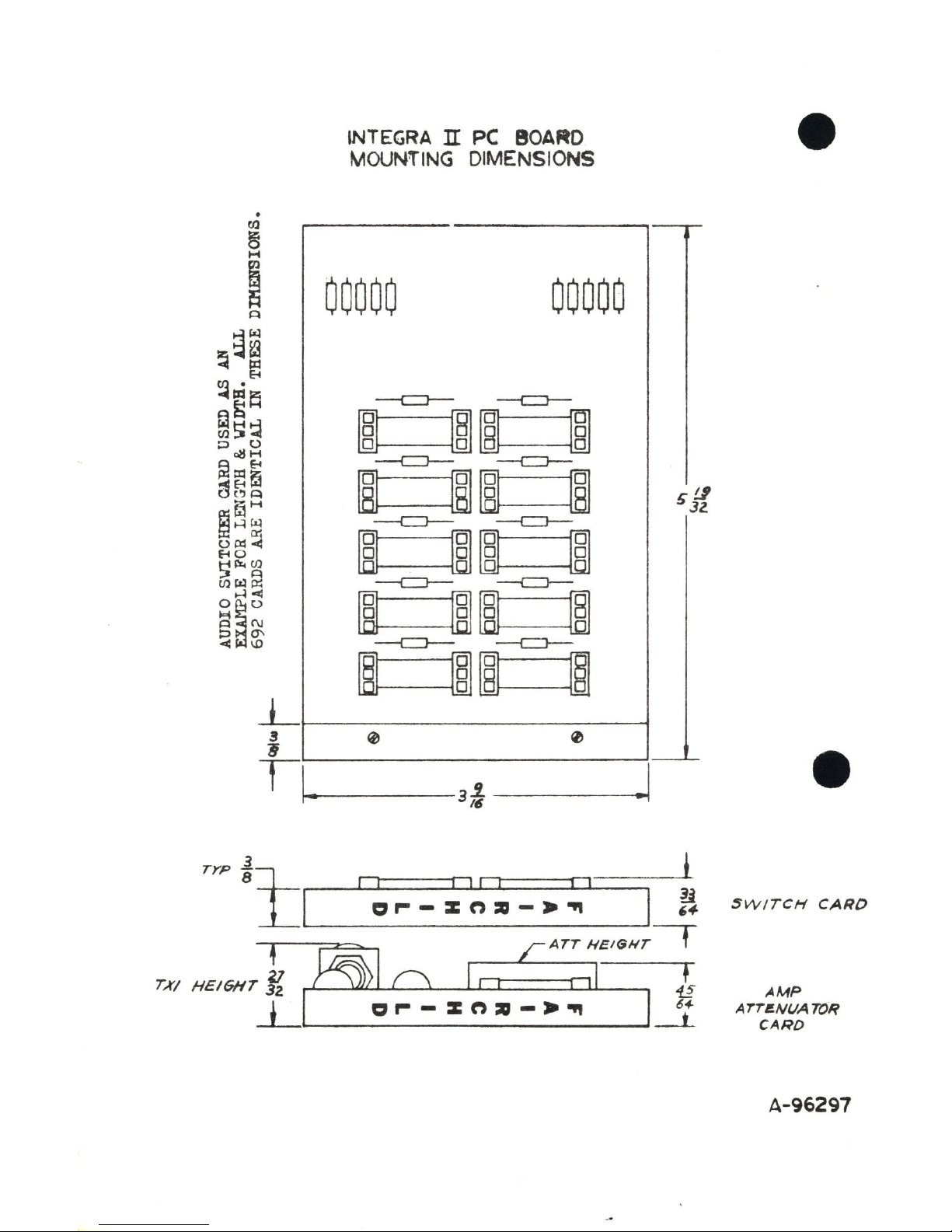
Fairchild Integra II Series User manual

Fairchild
Fairchild 610 User manual

Fairchild
Fairchild 2N4123 User manual

Fairchild
Fairchild 610 User manual

Fairchild
Fairchild 692DCA User manual

Fairchild
Fairchild 870 User manual

Fairchild
Fairchild 692LA-30 User manual

Fairchild
Fairchild 870 User manual