Faithtech FTP3000 Series User manual

Programmable DC Power Supply
User’s Manual
(FTP3000 Series)
©Copyright Faithtech
Version V1.01
2021-07


____________________________________________________________________________
- 1 -
Preface
Dear Sirs,
Thank you for purchasing Faithtech FTP3000 series programmable DC power supplies. This manual contains
detailed information about FTP3000 Series’ installation, operation, and specifications, etc..
Please read this manual carefully for using this product safely and correctly, especially safety precautions.
Please keep this manual properly for future use.
Notice
All rights are reserved by Faithtech. This manual is only for reference. Information may be revised without
prior notice. Faithtech shall not be liable for possible errors or damages caused by using this manual.
Please visit our website http://www.faithtech.cn for latest information.
Product Warranty
Faithtech promises that specifications and features of FTP3000 Series power supplies have completely met
all technical indexes claimed in this manual. We strictly check raw materials and manufacturing technology
to ensure the stability and credulity of products.
Warranty Service
From the date of purchase warranty, within the one-year warranty period, Faithtech will provide free repair
for all faults in the normal usage and maintenance of the product. The user need prepay one-way freight for
sending the product to the service department. The return freight will be paid by Faithtech. If products are
returned from other countries for maintenance service, then you should pay all freight, duties and other
taxes.
Warranty Limitation
The warranty is only limited to the power supply host. Faithtech will not provide free repair if the product is
damaged by misuse, negligence, unauthorized modifications, abnormal application environment or force
majeure, instead Faithtech shall provide estimated maintenance cost before the repair.
This warranty is in lieu of all other warranties. Faithtech does not make any other warranties, expressed or
implied, including guarantees of merchantability, reasonableness and applicability of certain specific
applications, which might arise in the contract, civil negligence or others.
Faithtech assumes no responsibility for its product being used in a hazardous or dangerous manner either alone
or in conjunction with other equipment. High voltage used in some instruments may be dangerous if misused.
Special disclaimers apply to these instruments. Faithtech assumes no liability for any special, incidental or indirect
damages.

FTP3000 Series Programmable DC Power Supply Operation Manual
____________________________________________________________________________
- 2 -
Safety Abstract
Please observe important safety instructions strictly in the process of operating and using the power supply. Not
observing safety precautions or warnings in this manual will probably weaken protective functions provided by
the power supply. Faithtech will not assume any liability for damages if the user does not observe those safety
precautions.
Important Safety Instructions
■Ensure proper grounding. Before turning on the power supply, please make sure that the power supply
is reliably grounded to prevent electric shock.
■Single phase 220VAC input. Make sure the input wire meets the specified standards, and a protective
cover must be installed to prevent electric shock.
■Output cable connection. Make sure the output wire meets the specified standards, and a protective
cover must be installed to prevent electric shock.
■Do not open the instrument case. Operators are not allowed to open the shell of the power supply.
Non-professionals are not allowed to repair or adjust.
■Do not use in a hazardous or dangerous manner either alone or in conjunction with other equipment.
Operating in inflammable or explosive environment is strictly forbidden.
Safety Symbols
Please see the following table for meanings of international symbols applied in the mainframe or the user’s
manual.
----------------------------------------------------------------------------------------------------------------------
WARNING: To avoid injury, death of personnel, or damage to the instrument, the operator
must refer to the explanation in the instruction manual.
----------------------------------------------------------------------------------------------------------------------
High temperature: This symbol indicates the temperature is hazardous to human beings.
Do not touch it to avoid any personal injury.
----------------------------------------------------------------------------------------------------------------------
DANGER: High voltage.
---------------------------------------------------------------------------------------------------------------------
Protective grounding terminal: This symbol indicates that the terminal must be
connected to ground before operation of the equipment to protect against electrical
shock in case of a fault.
----------------------------------------------------------------------------------------------------------------------

____________________________________________________________________________
- 3 -
----------------------------------------------------------------------------------------------------------------------
The WARNING sign highlights an essential operating or maintenance procedure, practice,
condition, statement, etc., which if not strictly observed, could result in injury to, or death of
personnel or long term heath hazards.
----------------------------------------------------------------------------------------------------------------------
The CAUTION sign highlights an essential operating or maintenance procedure, practice,
condition, statement, etc., which if not strictly observed, could result in damage to, or
destruction of equipment.
----------------------------------------------------------------------------------------------------------------------
The Notice sign highlights an essential operating or maintenance procedure, condition,
or statement.
------------------------------------------------------------------------------------------------------------------------------------------
More safety symbols table

FTP3000 Series Programmable DC Power Supply Operation Manual
____________________________________________________________________________
- 4 -
Table Of Contents
1. GENERAL DESCRIPTION...................................................................................................................................... - 6 -
1.1 Overview.................................................................................................................................................... - 6 -
1.2 Main features...........................................................................................................................................- 6 -
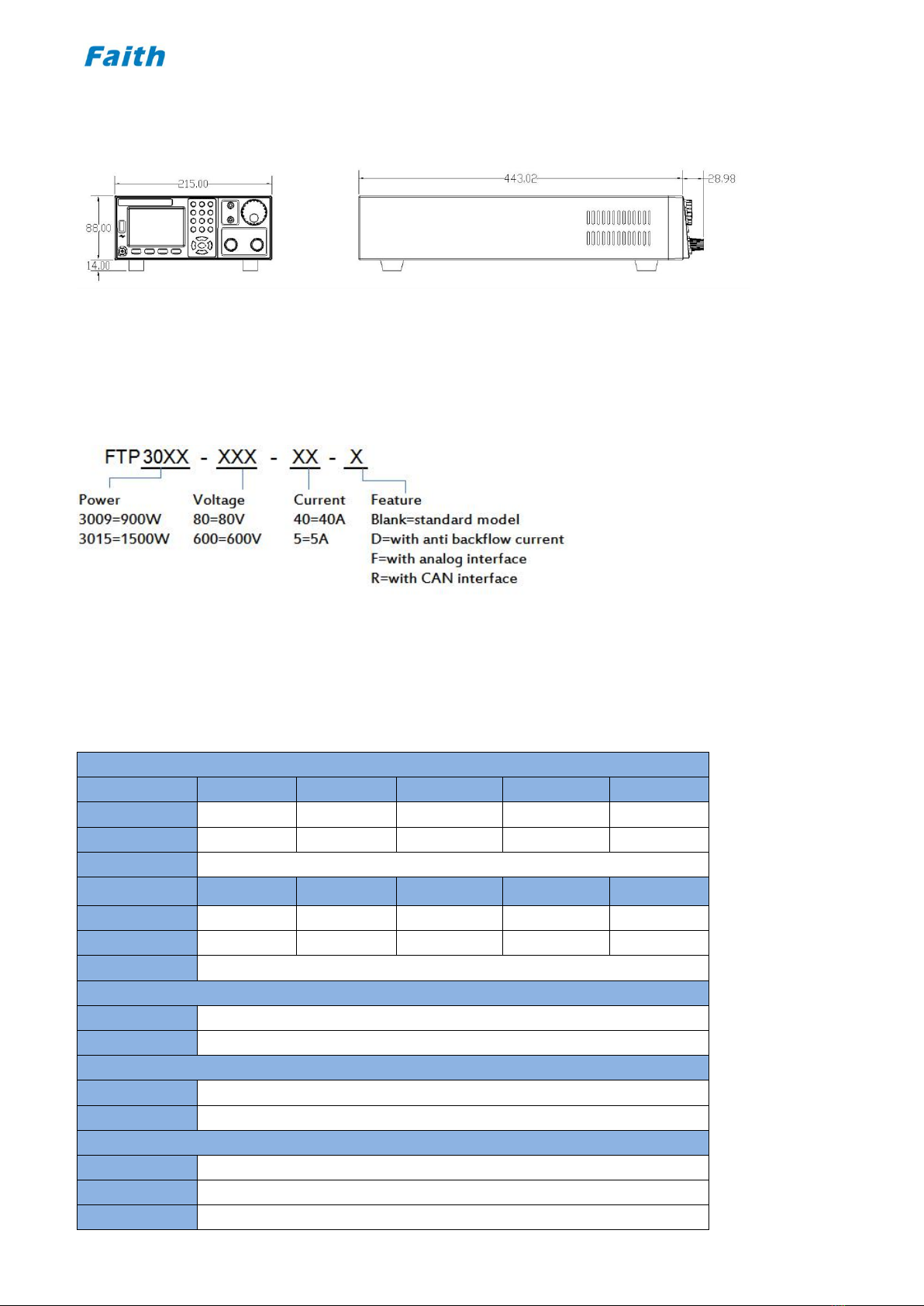
1.3 Dimension diagram...............................................................................................................................- 7 -
1.4 Model Naming..........................................................................................................................................- 7 -
1.5 Specification sheet.............................................................................................................................. - 7 -
2. Quick Guide.................................................................................................................................................................- 9 -
2.1 Checking Goods..................................................................................................................................... - 9 -
2.2 Front Panel..............................................................................................................................................- 10 -
2.3 Keyboard..................................................................................................................................................- 10 -
2.4 Screen Display......................................................................................................................................- 12 -
2.5 Rear Panel...............................................................................................................................................- 13 -
2.6 Installing.................................................................................................................................................. - 14 -
2.6.1 Preparation For Use.......................................................................................................................... - 14 -
2.6.2 Requirements of Input Power......................................................................................................... - 14 -
2.6.3 Power ON Self Check........................................................................................................................- 14 -
2.7 Connection..............................................................................................................................................- 15 -
2.7.1 Output Connection........................................................................................................................... - 15 -
2.7.2 V-Sensing Connection...................................................................................................................... - 15 -
2.7.3 Analog Interface................................................................................................................................ - 16 -
3. FUNCTION INTRODUCTION..............................................................................................................................- 17 -
3.1 Local & remote operation mode.................................................................................................- 17 -
3.2 Menu Layout...........................................................................................................................................- 17 -
3.2.1 Set Menu............................................................................................................................................ - 17 -
3.2.2 Edit Menu........................................................................................................................................... - 19 -
3.2.3 About Menu....................................................................................................................................... - 19 -
3.3 VI (CV/CC) Output Function........................................................................................................... - 19 -
3.4 Voltage Slew Rate & Current Slew Rate............................................................................... - 20 -
3.5 CV/CC Priority Start function........................................................................................................- 21 -
3.6 Output On/Off Control....................................................................................................................... - 22 -
3.7 Analog Programming.........................................................................................................................- 22 -
3.8 Trigger....................................................................................................................................................... - 23 -
3.9 Protection................................................................................................................................................- 24 -
3.10 Save and Recall.................................................................................................................................- 26 -
3.10.1 Save Operation................................................................................................................................ - 26 -
3.10.2 Recall Operation..............................................................................................................................- 26 -
3.10.3 Shortcut Recall.................................................................................................................................- 27 -
3.11 Power Save & Power On Auto Output...................................................................................- 27 -
3.12 External Control................................................................................................................................ - 28 -
3.13 Output Mode & Status Digital Signal Output.................................................................... - 29 -
3.14 Lock and unlock................................................................................................................................- 29 -

____________________________________________________________________________
- 5 -
3.15 SEQ (Sequence) Test Setting.................................................................................................... - 30 -
3.16 Constant Power Output (CP) Setting.....................................................................................- 32 -
3.17 Internal Resistance Simulation (RESI).................................................................................- 33 -
3.18 RAMP Output.......................................................................................................................................- 34 -
3.19 Sound...................................................................................................................................................... - 36 -
3.20 Language...............................................................................................................................................- 36 -
4. COMMUNICATION INTRODUCTION..............................................................................................................- 37 -
4.1 Communication Interface...............................................................................................................- 37 -
4.1.1 RS232.................................................................................................................................................. - 37 -
4.1.2 LAN......................................................................................................................................................- 37 -
4.1.3 CAN..................................................................................................................................................... - 38 -
4.2 Communication Configuration Modification........................................................................ - 38 -
4.3 Communication Protocol................................................................................................................ - 39 -
4.3.1 SCPI Protocol..................................................................................................................................... - 39 -
4.3.2 Modbus Protocol...............................................................................................................................- 39 -
4.3.3 CANopen protocol............................................................................................................................ - 39 -
5. TROUBLESHOOTING............................................................................................................................................ - 40 -
6. APPENDIX...................................................................................................................................................................- 41 -

FTP3000 Series Programmable DC Power Supply Operation Manual
____________________________________________________________________________
- 6 -
1. General Description
1.1 Overview
FTP3000 series programmable DC power supply is a power supply with super practicality and versatility
developed by Faith after years of experience in the design and development of DC switching power supplies.
FTP3000 series power output range 900W/1500W, output voltage up to 600V, current up to 80A. It can be
widely used in various test environment such as laboratory test, vehicle equipment test, solar inverter test,
DC/DC converter and inverter test, engine start test, automatic battery charging, and electronic product life
cycle test.
1.2 Main features
■Output voltages: 40 V, 80 V, 150 V, 300 V, 600 V;
■Output current: 5 A, 10 A, 20 A, 40 A, 80 A;
■Output power: 900 W, 1500 W;
■Constant power output;
■Precision V & I measurement;
■High speed programming;
■1ms typical transient response;
■Programmable sequence;
■Voltage & current slew rate control;
■CV / CC priority start;
■Foldback protection;
■Wide operating region for output;
■Internal resistance simulating;
■Remote sense compensation;
■Optional analog programming & monitoring interface;
■±OVP, ±OCP, ±OPP, OTP, ±LVP;
■Voltage limit, current limit;
■Standard RS232, LAN, optional GPIB and CAN ports;
■SCPI and ModBus RTU protocol
■TFT color LCD display.

____________________________________________________________________________
- 7 -
1.3 Dimension diagram
1.4 Model Naming
1.5 Specification sheet
Specification table-1
Model
FTP3009-40-80
FTP3009-80-40
FTP3009-150-20
FTP3009-300-10
FTP3009-600-5
Voltage
0~40V
0~80V
0~150V
0~300V
0~600V
Current
0~80A
0~40A
0~20A
0~10A
0~5A
Power
900W
Model
FTP3015-40-80
FTP3015-80-40
FTP3015-150-20
FTP3015-300-10
FTP3015-600-5
Voltage
0~40V
0~80V
0~150V
0~300V
0~600V
Current
0~80A
0~40A
0~20A
0~10A
0~5A
Power
1500W
Voltage programming
Resolution
16Bits
Accuracy
0.1%+0.1%F.S.
Current programming
Resolution
16Bits
Accuracy
0.1%+0.2% F.S.
External analog programming
Control voltage
0~5V corresponds to 0~100%F.S.
Voltage accuracy
0.2%F.S.
Current accuracy
0.5%F.S.

FTP3000 Series Programmable DC Power Supply Operation Manual
____________________________________________________________________________
- 8 -
Analog output
Output voltage
0~100%F.S. corresponds to 0~5V.
Voltage accuracy
0.5%F.S.
Current accuracy
0.5%F.S.
Line regulation
Voltage
0.01%+0.01%F.S.
Current
0.02%+0.01%F.S.
Load regulation
Voltage
0.01%+0.05%F.S.
Current
0.02%+0.1%F.S.
Voltage measurement
Resolution
16Bits
Accuracy
0.1%+0.1%F.S.
Current measurement
Resolution
16Bits
Accuracy
0.1%+0.2%F.S.
Output noise & ripple
Ripple Vpp
40mV
60mV
80mV
150mV
300mV
Ripple Vrms
10mV
20mV
20mV
30mV
60mV
Slew rate
Voltage
5V/ms(max)
Current
2A/ms(max)
OVP setting
Range
0~110%F.S.
Accuracy
1%F.S.
Transient response
Typical 1ms, voltage recover to the designed accuracy after a 50% change of load
Efficiency
0.9(Typical)
Communication
RS232, LAN
INPUT
190VAC~265VAC, 47Hz~63Hz, PF: 0.99(Typical)
Working temp
0℃~40℃
Storage temp
-20℃~70℃
Altitude
<2000m
Size
215 (W)×88(H)×452.5(D)mm
Weight
7kg

____________________________________________________________________________
- 9 -
2. Quick Guide
2.1 Checking Goods
Upon reception of the power supply, please examine the equipment according to procedures stipulated as below.
(1) Check if there is damage during transportation.
Contact authorized dealer or Faithtech after-sale service immediately if the packing or protective cushion is
severely damaged.
-----------------------------------------------------------------------------------------------------------------------
Do not return the instrument without obtaining prior approval from Faithtech.
-----------------------------------------------------------------------------------------------------------------------
(2) Check for the accessories.
Make sure you have received the following accessories along with the power supply:
Table 2-1 Accessories Explanation
Accessory
QTY
Explanation
AC input power cable
1 PCS
220VAC input power cable
RS232 communication cable
1 PCS
For connecting PC and RS232 port
LAN communication cable
1 PCS
For connecting PC and LAN port
User Manual
1 PCS
Installing and operation info
CD Disk
1 PCS
Tech info
Warranty and after-sale info
1 PCS
Warranty and after-sale info
Contact authorized dealer or Faithtech after-sale service immediately if there is damage or miss.
(3) Check for the power supply unit.
Contact authorized dealer or Faithtech after-sale service immediately if the power supply case is damaged or
working abnormally.
(4) Cleaning.
If you need to clean the casing of the machine, please wipe it gently with a dry cloth or a slightly damp cloth. Do
not wipe the inside of the machine.
-----------------------------------------------------------------------------------------------------------------------
Turn off the power supply before cleaning.
-----------------------------------------------------------------------------------------------------------------------

FTP3000 Series Programmable DC Power Supply Operation Manual
____________________________________________________________________________
- 10 -
2.2 Front Panel
Figure 2-1 FTP3000 Front Panel
①Power switch
②Multi-function key
③TFT color screen
④Numeric number key and decimal point key (input data or work with “shift” key for compound operation.
⑤Cursor Move Direction key and Enter key
⑥Power supply Output terminal
⑦V-sense terminal
⑧Adjusting rotary knob
2.3 Keyboard
Figure 2-2 FTP3000 keyboard

____________________________________________________________________________
- 11 -
Table 2-2 Key Function Descriptions
Button
Description
Multi-function key, the corresponding key function is displayed in screen above the key
Input numeric numbers, or work with “Shift” key to perform the functions underneath
Decimal point key
Exit edit state or current menu.
Cursor move up
Cursor move down
Cursor move left
Cursor move right
Enter into sub item, or enter into edit state, or confirm input parameter.
Table 2-3 Compound Operation Descriptions
Button
Description
Save present parameter setting into internal memory location
Recall the saved parameters
Clear protection state and information
Select advance test function
Enter into menu setting
Lock/unlock the keyboard
Trigger

FTP3000 Series Programmable DC Power Supply Operation Manual
____________________________________________________________________________
- 12 -
2.4 Screen Display
Figure 2-3 MAIN PAGE Display
①Status prompt area; ②Readback voltage, current, etc. parameters display area;
③Parameter setting area; ④Multi-function key indication;
About Status prompt area:
Output mode: CV, CC
Analog programming: Blank (analog program is Off), P-U, P-I, P-UI
V-SENSE: Blank (local sensing), Sense (Remote sensing)
Protection: Blank (no protection occurred), PFCF, SDF, OT, OCP, OPP, LVP, AMP, E01, E02, OC, OP, OV, OVP, OCVP,
RVP, COMF
Output indicator: Off (output turned off), On (output turned on)
About readback V, I parameters display area:
Displays readback voltage, current, power, measurement result etc.. However, the actual displayed information
varies, for example, in voltage/current static output mode, the area displays output voltage, current and power; in
sequence test mode, the area displays output voltage, current, sequence current steps and sequence cycle times.
About parameters setting area:
1. Rotate the rotary knob or press the direction key to move the cursor to the parameter to be edited;
2. Press “Enter” key to enter into parameter edit state;
3. Press numeric number key or rotate the rotary knob to input value;
4. Press “Enter” to validate the input and exit editing state.
About multi-function key indication:
: switch to VI (constant voltage/current) output mode, cursor is in voltage parameter;
: switch to VI (constant voltage/current) output mode, cursor is in current parameter;
: work with number key together for performing functions written underneath;
: Turn on/off power supply output.

____________________________________________________________________________
- 13 -
2.5 Rear Panel
Figure 2-4 FTP3000 Rear Panel
Item
Name
Description
1
CAN (optional)
The remote controller uses the CAN connector to connect to a
PC for remote operation.
2
RS232
The remote controller uses the RS232 connector to connect to
a PC for remote operation.
3
Ventilation port
Ventilation
4
Analog interface (optional)
This interface has the functions of analog programming input,
voltage/current monitoring output, external control, power
supply status and work mode digital signal output.
5
LAN
The remote controller uses the LAN connector to connect to a
PC for remote operation.
6
AC INPUT
Single phase AC input: 190VAC~265VAC, 47~63Hz;
7
Ventilation port
Ventilation

FTP3000 Series Programmable DC Power Supply Operation Manual
____________________________________________________________________________
- 14 -
2.6 Installing
2.6.1 Preparation For Use
(1) Ensure the Power Supply is connected to the AC line input that meets the specification.
(2) The instrument must be installed in an area with good air circulation to avoid the internal temperature getting
too high.
(3) For indoor use only, ambient temperature 0°C to 40°C.
2.6.2 Requirements of Input Power
Please pay attention to the following items for FTP3000 series power supply input connection:
①Single phase AC input: 190VAC~265VAC, 47~63Hz;
②The AC input power cord is a 3-core cable with grounding connection, DO NOT operate the instrument if there
is no proper socket;
③There is 1PCS AC input power cable included with the accessories, which should be compatible with your local
electric voltage. Contact Faithtech agent or after-sale service immediately if you find the input cable is not
matching with the power supply AC input terminal.
----------------------------------------------------------------------------------------------------------------------------
The instrument provides mainframe grounding connection via 3-core power cable. Make
sure there is proper ground connection in applying socket before operation. Under no
circumstances shall this DC Power Supply be operated without an adequate ground
connection.
----------------------------------------------------------------------------------------------------------------------------
2.6.3 Power ON Self Check
When powered on, the power supply will conduct self check, the check process and results will be displayed on
the screen, such as below:
Figure 2-5 FTP3000 Power ON Self Check
The power supply will enter MAIN PAGE if all checking results are OK, otherwise it will wait for 3 seconds before
entering MAIN PAGE.
If there is FAULT during power supply power on self check, please refer to “Table 5-2 Power On Self-Check Fault”.

____________________________________________________________________________
- 15 -
2.7 Connection
2.7.1 Output Connection
The device under test positive and negative input terminal is connected to the “+” and “-” output terminals on the
front panel of the power supply respectively. When connecting, pay attention to the wire diameter, length and
polarity of the output cable. To prevent the wire diameter from being too small to affect the test accuracy and
generate large heat to cause safety accidents, please refer to "Table 6-1 Recommended Wire Diameters for
Cables" for wire diameter selection.
Figure 2-6 Power Supply Output Connection
----------------------------------------------------------------------------------------------------------------------
The diameter of the wire connected to the load must be adequate so as to carry the
maximum applied current.
----------------------------------------------------------------------------------------------------------------------
2.7.2 V-Sensing Connection
There are two kinds of V-sensing: local V-sensing and remote V-sensing.
FTP3000 series power supplies are able to compensate for the voltage drop caused by output connecting cables.
For remote sensing, be sure to connect the power supply’s remote sense connector “+S” to the load’s positive
input terminal and the “–S” connector to the load’s negative input terminal. Do not reverse the connections.
Figure 2-7 Power Supply Remote V-Sense Connection

FTP3000 Series Programmable DC Power Supply Operation Manual
____________________________________________________________________________
- 16 -
2.7.3 Analog Interface
FTP3000 series power supply provides optional analog Interface at its rear panel. This interface has the functions
of analog programming input, voltage/current monitoring output, external digital signal input, power supply
status and work mode digital signal output.
Figure 2-8 Analog Interface
Table 2-5 Analog Interface PIN Function Description
PIN
Name
I/O
Description
1
VSET-
Input
Power supply voltage analog programming port negative terminal, input signal range 0~5V
2
VSET+
Input
Power supply voltage analog programming port positive terminal, input signal range 0~5V
3
ISET-
Input
Power supply current analog programming port negative terminal, input signal range 0~5V
4
ISET+
Input
Power supply current analog programming port positive terminal, input signal range 0~5V
5
GND
---
Reference ground
6
IMON
Output
Power supply output current monitoring port, monitor output range 0~5V
7
GND
---
Reference ground
8
VMON
Output
Power supply output voltage monitoring port, monitor output range 0~5V
9
MODE
Output
Output mode indicating port. The port outputs low level signal under CV mode, high level
signal under CC mode
10
GND
---
Reference ground
11
INHIBIT
Input
External control, used as trigger signal or output on/off control signal
12
READY
Output
Power supply working state indicator, the port outputs High level signal if working normally,
low level signal if fault or protection
----------------------------------------------------------------------------------------------------------------------
1. The digital signal level is 0~5V.
2. The analog interface terminal is electrically isolated from the power supply output
terminal.
----------------------------------------------------------------------------------------------------------------------

____________________________________________________________________________
- 17 -
3. Function Introduction
This chapter describes the main functions and characteristics of the power supply. Reading this chapter, you will
have a deeper understanding of FTP3000 series power supplies.
3.1 Local & remote operation mode
The power supply provides two operation modes: local operation and remote operation. In the local operation
mode, the user mainly operates through the keyboard and knob on the front panel, and checks the power status
through the LCD display; in the remote operation mode, the user mainly performs settings and operations via the
communication interface and programming commands.
Local operation mode
When the power supply is turned on, it operates in local operation mode by default. In this mode, the user
operates the power supply through the front panel keyboard and rotary knob. The LCD screen provides users with
display functions such as parameter viewing, measurement display and status indication.
Some parameters can only be set in local mode, including:
System language
Serial port baud rate and parity method
Key sound
IP address and subnet mask
Communication protocol
Remote operation mode
To enter the remote operation mode, please use the proper communication cable to connect the PC with the
power supply. The communication configuration parameters must be consistent with the control device settings.
Upon receiving the programming command, the power supply automatically switches to the remote operation
mode from local control mode.
In remote control mode, all other keys are disabled except key, and the power supply can only be
controlled by programming commands. Press on the front panel to return to local operation mode.
3.2 Menu Layout
3.2.1 Set Menu
Press to enter into main menu, then select “Set” and press to pop up
sub menu as below:

FTP3000 Series Programmable DC Power Supply Operation Manual
____________________________________________________________________________
- 18 -
Table 3-1 Set Menu Layout
System
IP
Default 192.168.1.123
S-Mask
Default 255.255.255.0
Baud
Serial port baud rate, 4800/9600/19200/38400/115200, default: 9600.
Parity
None/odd parity/even parity, default: None
Sound
Keyboard sound ON/OFF. Default: ON
Power Save
Power down save function ON/OFF. Default: ON
Language
Simplified Chinese/Traditional Chinese/English. Default: English.
Shortcut
Fast recall function ON/OFF. Default: Off
Power On
Define power supply output On/Off state at its power on moment. Default: Off
Output
V_MAX
Upper limit of static VI output voltage set , default 100%F.S. output voltage
V_MIN
Lower limit of static VI output voltage set, default 0
I_MAX
Upper limit of static VI output current set, default 100%F.S. output current
I_MIN
Lower limit of static VI output current set, default 0
V_SLEW
Set Voltage slew rate for static VI output, range: 0.001V/s~5000V/s, default 5000V/s
I_SLEW
Set current slew rate for static VI output, range: 0.001A/s~2000A/s, default 2000A/s
Protect
OVP
Set overvoltage protection threshold, set 0 to turn off this protection, default 0
OCP
Set overcurrent protection threshold, set 0 to turn off this protection, default 0
OPP
Set overpower protection threshold, set 0 to turn off this protection, , default 0
FoldBack
Monitor output mode, protection is triggered when mode changes, settable among
choices: OFF / CC-to-CV / CV-to-CC, default set OFF
Fold-Time
Output mode changes must last for a set time for protection to be triggered. Time range:
0.1s to 600.0s
LVP
Set low voltage protection threshold, default set 0 to turn off this protection.
Reverse
Turn on/off reverse voltage protection, default value: OFF
Comm_Dog
Set communication time out protection, range: 0.0~3600.0s, set 0 to turn off this
protection;
APP Set
Prio_Slt
Choice for CV or CC priority start. Default value: Volt (CV Priority)
EXT-Single
Choose external control signal behavior, Trigger/Toggle/Hold, default: Trigger
APG
Choose external programming mode, Off/U/I/U+I, default: Off.
Response
Choose response speed in CP output mode, range 1~100%, default 50%
Sense
Choose V-sense type, local/remote, default local
Comm Pro
Choose communication protocol, SCPI/Modbus, default Modbus
DevAddr
Set device address in Modbus protocol, range 0~254
Factory
Reset to factory setting. Restart the instrument for changes to take effect.
Table of contents
Other Faithtech Power Supply manuals
Popular Power Supply manuals by other brands

nextys
nextys NUPS12 instruction manual

Ubiquiti
Ubiquiti EdgePower EP-54V-150W quick start guide

Elenco Electronics
Elenco Electronics XP-603 instruction manual

SIEB & MEYER
SIEB & MEYER PS10 Hardware description

Wheelock
Wheelock POWERPATH series PS-12-24-8CP installation instructions

Dell
Dell EU2SPE Disassembly instructions