Solar-Log 2050 User manual

®
Solar-Log® Installation Manual
Solar-Log 2050 Assembly

Table of Contents
1 Important Safety Instructions 3
2 Package Contents 4
2.1 What’s in your shipment 4
3 Assembly 5
4 Installation 7
5 Wiring 8
6 Configuration 12
6.1 Connecting the Solar-Log to a network/PC 12
6.2 Setting up the Solar-Log using the configuration Assistant 13
7 Appendix A: CT Placement 24

3
1 Important Safety Instructions
Save These Instructions
The Solar-Log 2050 Assembly is used in conjunction with a Solar-Log® data logger that is capable of communicating with a
wide variety of inverters, and one or several inverters of choice that can produce hundreds of AC current amps. These Safety
Instructions are to help ensure safe installation and operation of the Solar-Log 2050 and the equipment it is connected to. Be
sure to read the instructions which came with the Solar-Log 2050 and all other connected equipment carefully. Inspect the
Solar-Log 2050 and all other equipment and read all cautionary and instructive markings on all equipment. Be sure to follow
all cautions and instructions when installing all equipment. Save this manual, it has important maintenance and operation
information.
Proper equipment grounding must be performed as directed in the grounding section of this manual.
THIS IS THE SYMBOL FOR GROUND:
THIS IS THE SYMBOL FOR DIRECT CURRENT (DC):
THIS IS THE SYMBOL FOR ALTERNATING CURRENT (AC):
• Use appropriate size conductors rated for at least 90º C.
• Torque all connections as recommended in this manual.
Solar Data Systems, Inc. requires that all wiring must be done by a licensed electrician or certified technician in accordance
to all local and national electrical codes applicable in your jurisdiction. Do not perform electrical work without the proper
qualifications.
To avoid a risk of fire and electric shock, make sure that existing wiring is in excellent condition and that the conductors are
correctly rated. Do not operate any system components with damaged or substandard conductors. Use only attachments
recommended or sold by Solar Data Systems, Inc. or our Authorized Distribution Partners. Attaching other devices may result
in a risk of fire, electric shock, or injury to persons. To reduce the risk of electrical shock, disconnect all sources of AC and DC
power from the Solar-Log 2050 before removing the cover and attempting any maintenance or working on any components
connected to the Solar-Log 2050.
Intended Use
The Solar-Log 2050 is designed for use only with Solar Data Systems, Inc. equipment. Any inappropriate application may result
in a fire hazard or personal injury.
Warning
The Solar-Log 2050 is designed for indoor or outdoor use. The enclosure is rated IP66 which oers resistance to dust and
sprayed water infiltration. It must be installed using the proper fittings to maintain this rating. Failure to do so in damp
environments will significantly shorten the life of this product and may aect the product warranty.
Do not mount the Solar-Log 2050 Enclosure in an area exposed to direct sunlight. It must be placed in a constantly shaded
area.
Do not disassemble the Solar-Log 2050. The Solar-Log 2050 does not have any user-serviceable parts.
Always use insulated tools to reduce the chance of short-circuits when installing or working with power connections, PV arrays
and any other connected equipment. To further reduce the risk of exposure to live circuits remove all jewelry while installing this
system.

4
2 Package Contents
2.1 What’s in your shipment
Figure 2.1: Solar-Log 2050, Current Transformers (CTs), Solar-Log® Data Logger
The shipment comes with the following components:
• Solar-Log 2050 (art. no. 840850): In an indoor/outdoor enclosure, the assembly includes a revenue grade meter, power
supply, fusing blocks, shorting blocks, RS485/422 ports, and a swing frame
• Current Transformers (CTs) models and number of units vary
• One of the following Solar-Log® data logger models: Solar-Log 1200 (art. no. 255591), Solar-Log 1900 (art. no. 256241),
Solar-Log 2000 (art. no. 255592)
Note:
If you are using the Solar-Log 2050 assembly for consumption monitoring only, the Solar-Log® data logger might not be
included in your shipment. The Solar-Log 2050, Solar-Log® Data Logger, and CTs are all sold separately.

5
3 Assembly
1. Remove the front cover on the Solar-Log 2050 enclosure by uscrewing the 4 plastic captive screws.
2. Remove the 2 screws (Figure 3.1) & open the swingframe.
Figure 3.1: Swing Frame Screws

6
3. Mount the Logger to the swingframe using the screws, nuts & washers provided. Be sure to guide wires under the wire guide
of the Logger (Figure 3.2).
Figure 3.2: Logger screw holes for attaching to swing frame & wire guide on the back of the Logger.
4. Connect the DC Power, Port A & Port B connectors to the Logger (Figure 3.3).
Figure 3.3: Logger Connections
7
4 Installation
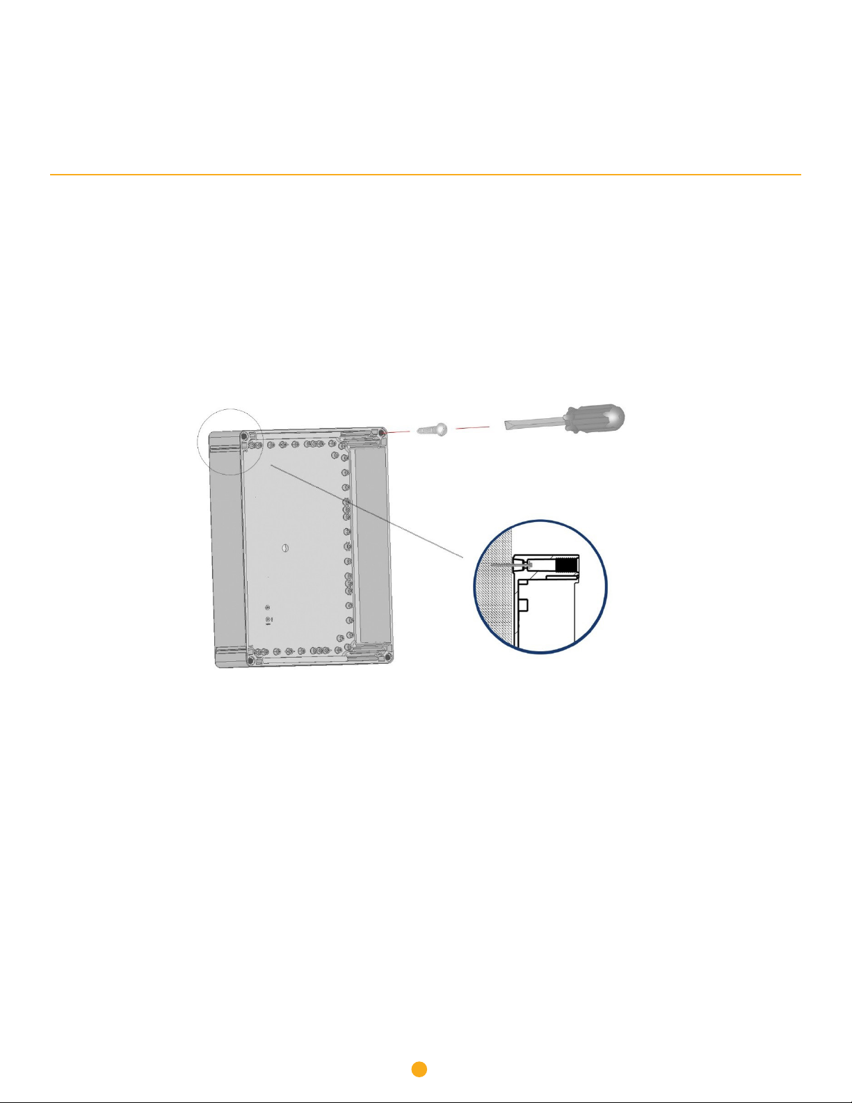
1. Select a suitable wall location and use suitable rustproof screws to secure Solar-Log 2050 unit to the support. Dierent
anchors and screws for fitting the Solar-Log 2050 box are required depending on the support. Therefore anchors and screws
for mounting are not supplied (Figure 4.1).
2. Drill the needed conduit holes for mains power and other connections. Run power mains and communication lines in
separate conduit.
Note: DO NOT DRILL OR SCREW DIRECTLY INTO THE ENCLOSURE! In order to keep the enclosure waterproof and maintain its
environmental (IP) ratings please use the 4 pre-drilled mounting/lid holes for fastening the enclosure to the wall.
Figure 4.1: Mounting Instructions
Wall Screw
Cover Screw
8
5 Wiring
Note:
Before you start wiring make sure the system is de-energized. Refer to Figures 5.3 & 5.4:
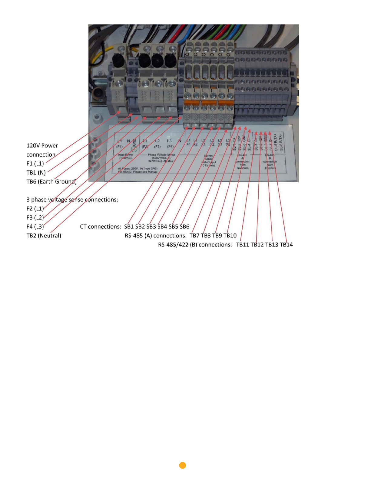
1. Connect the input power to F1 (line) and N (Neutral) and GND (Ground). Torque F1 to 17.7 in-lbs. (2Nm), and N and GND to 5.3
in-lbs. (0.6Nm).
2. Connect the 3 phase voltage sense wires to F2 (L1), F3 (L2), F4 (L3), and N (Neutral). Torque F2 - F4 to 17.7 in-lbs. (2Nm),
and N to 5.3 in-lbs. (0.6Nm).
3. Install current transformers (CTs) on the mains voltage feed wires. Refer to CT labeling for Source/Load direction and see
Appendix A.
4. Connect the CT sense wires to the appropriate terminals. Torque terminal connections to 5.3 in-lbs. (0.6Nm).
Note:
Connect the CT X1 wire to the X1 terminal and the X2 wire to the X2 terminal. The CT sense wires may be extended, as
necessary. Splice 18 AWG hookup wires and minimize wire extension length to limit additional impedance on the circuit.
Note:
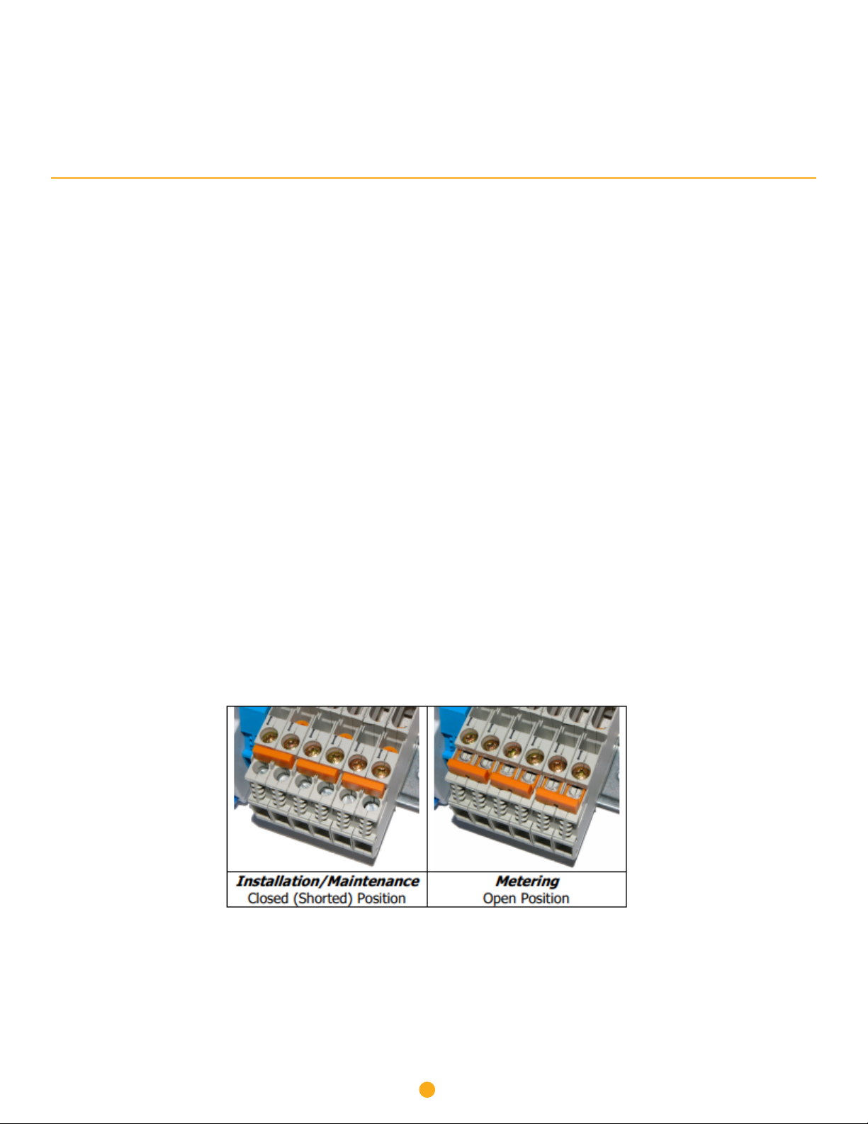
For 5A CT systems only: When the CT wires are in place on the short blocks (Figure 6) you must now lower the orange tab over
the screw terminals. This prevents access to the circuit with a screwdriver, as well as completes the circuit. Unscrew both the
screws near the “I” and pull the orange bar over the screw terminals. Re-fasten the screw closest to the “I”. The circuit is now
complete. The meter must NOT be disconnected when the shorting block is in the OPEN position.
Figure 5.1: CT Shorting Block

9
5. The RS-485 (or RS-422) connections between the Solar-Log® and Revenue Grade Meter are pre-wired. Connections to the
Inverter(s) are made to the RS-485 Port B terminals at the right side of the enclosure. Torque terminal connections to 5.3 in-lbs.
(0.6Nm).
6. Power the enclosure and wait for the Solar-Log® to complete its booting process.
7. For 3 phase systems, six green LED’s on the WattsOn meter should be solid (exception: bi-directional meter). If any of the
green LED’s in the bottom row are blinking the CT is in the wrong direction. Flip the CT or the wire leads in the terminal block.
If any of the six LED’s are red (solid or blinking) then the CT and voltage tap are phase mismatched. Swap CT leads in terminal
blocks till all six lights are green.
Figure 5.2: Elkor Meter LEDs
10
Note:
CT lead wire color can vary. Standard wire color is shown. Verify lead color of CT in manufacturer manual.
Terminals SB1-SB6 for mA meters are equipped with standard terminal blocks instead of shorting blocks.
Figure 5.3: Wiring Compartment

11
Note: The Solar-Log 2000 includes a third RS485/422 bus where buses B and C connect to the terminal blocks.
Figure 5.4: Three Phase Wiring Diagram

12
6 Configuration
• The Solar-Log® has an integrated web server, which contains all the software necessary for operation and configuration.
• No additional software needs to be installed on the PC to access the Solar-Log®. A common web browser with JavaScript
enabled is required. We recommend using the current version of Mozilla’s Firefox or Google’s Chrome.
• To run the web browser, a network connection is required between the PC and Solar-Log®, and Solar-Log® must be up and
running. It is recommended to have DHCP enabled on the router.
6.1 Connecting the Solar-Log® to a network / PC
The Solar-Log® is equipped with a standard Ethernet RJ45 socket, which can be connected through any commercially available
network cable. Speeds of 10 Mbit and 100 Mbit are supported. In general, any PC networking technology can be used for
connecting the Solar-Log®. The following technologies are available:
• Connection through an Internet router Ethernet RJ45 network cable (This is the preferred method).
• Direct cable connection from PC to Solar-Log® Ethernet RJ45 network patch cable. If connecting directly to a PC, the
cable must be the crossover network cable type (patch cable).
Note: A crossover cable may not be necessary if using a newer Laptop with Autosense.
Device URL
• Start the web browser.
• Enter http://solar-log in the address bar and press the ENTER key.
• The main menu of the Solar-Log® is displayed.
Device URL when there are several Solar-Log® devices on the network
• Start the web browser.
• Enter http://solar-log-wxyz in the address bar and press the ENTER key: Here wxyz stands for the last 4 digits from serial
number of the Solar-Log™. The serial number is printed on the model tag.
• The main menu of the Solar-Log® is displayed.
13
6.2 Setting up the Solar-Log® using the Configuration Assistant
Initial Setup
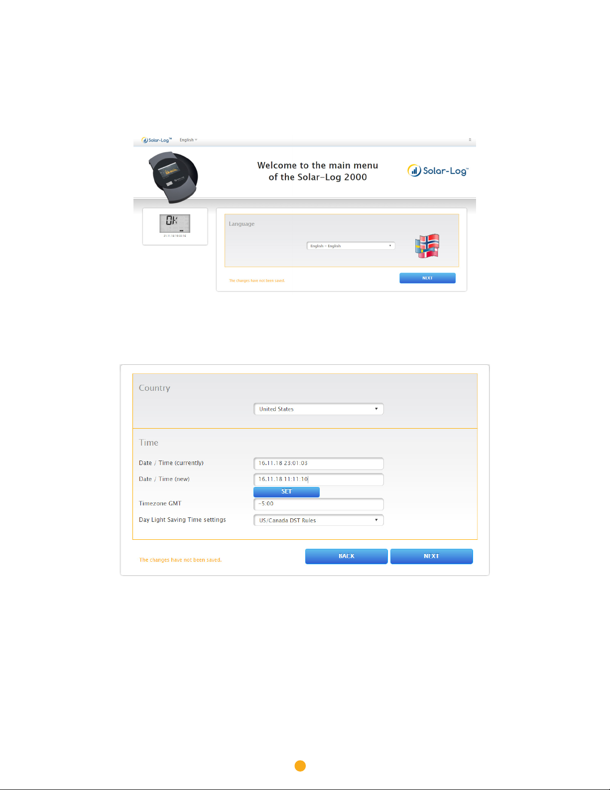
1. Select the correct language. Then Select NEXT.
2. Select the Country
a. Set the Date / Time. Note the format is MM.DD.YY HH:MM:SS (time is in 24hr format).
b. Select SET and verify the time Date/Time (currently) is now correct.
c. Set the Time Zone (EST= -5:00, CST = -6:00, MST = -7:00, PST = -8:00, HST = -10:00).
d. Set the Day Light Saving Time Settings to either US/Canada DST rules or None.
e. Select NEXT.
14
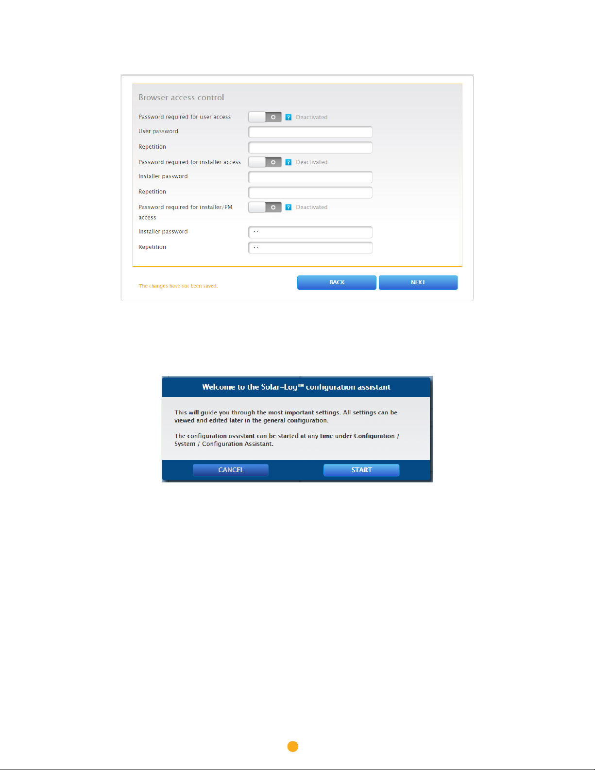
3. Set the password for the installer and/or the user if it is desired. Otherwise, set the Password required to Deactivated to
disable password protection of the local interface. Then select NEXT.
4. Select START to begin the Configuration Assistant.

15
Configuration Assistant
1. Set Obtain IP address automatically to Activated or fixed values may by entered.
2. Select CONNECTION TEST and the Logger will test the internet connection. This will take a few minutes.
3. Connection Test: If you get the above screen your internet settings are correct & you may continue by selecting OK.
4. Firmware-Update: Select NO. Upgrades can be done at later time.

16
5. Select the Blue +on the right side of the screen.
6. Set Device Class to Meter and fill in the information as shown above. Then select OK.
Note: Add any additional components the Solar-Log® it to communicate with.
Refer to Solar-Log-America.com>Support>Supported Components to get the settings.

17
7. Select START to begin searching for the defined components.
8. When the 1 Found is displayed you can select SKIP to continue to the next step in the process.

18
9. Click YES to apply the changes.
10. Click OK.

19
11. Select NEXT.
12. Verify that the Operating mode is set to Total plan meter.
13. If your system is using CT’s with the part # MRS-75 or MRS-125 on the label set the CT current to 37500000. For
all other CT models contact Solar-Log® Technical Support for assistance.
14. Set the Name to Solar Meter.

20
15. Enter the DC watts of the whole plant (Watts per panel x # of panels).
16. Select NEXT.
17. Set Activate transfers to Activated.
18. Enter the correct portal server for you company.
19. Select NEXT.
20. Select FINISH to complete the configuration.
Other manuals for 2050
1
Table of contents


