Faithtech FTP Series User manual

Programmable DC Power Supply
User’s Manual
(FTP Series)
©Copyright Faithtech
Version V1.06
2021-06


____________________________________________________________________________
- 1 -
Preface
Dear Sirs,
Thank you for purchasing Faithtech FTP Series programmable DC power supplies. This manual contains
detailed information about FTP Series’ installation, operation, and specifications, etc..
Please read this manual carefully for using this product safely and correctly, especially safety precautions.
Please keep this manual properly for future use.
Notice
All rights are reserved by Faithtech. This manual is only for reference. Information may be revised without
prior notice. Faithtech shall not be liable for possible errors or damages caused by using this manual.
Please visit our website http://www.faithtech.cn for latest information.
Product Warranty
Faithtech promises that specifications and features of FTP Series power supplies have completely met all
technical indexes claimed in this manual. We strictly check raw materials and manufacturing technology to
ensure the stability and credulity of products.
Warranty Service
From the date of purchase warranty, within the one-year warranty period, Faithtech will provide free repair
for all faults in the normal usage and maintenance of the product. The user need prepay one-way freight for
sending the product to the service department. The return freight will be paid by Faithtech.
Warranty Limitation
The warranty is only limited to the power supply host. Faithtech will not provide free repair if the product is
damaged by misuse, negligence, unauthorized modifications, abnormal application environment or force
majeure, instead Faithtech shall provide estimated maintenance cost before the repair.
This warranty is in lieu of all other warranties. Faithtech does not make any other warranties, expressed or
implied, including guarantees of merchantability, reasonableness and applicability of certain specific
applications, which might arise in the contract, civil negligence or others.
Faithtech assumes no responsibility for its product being used in a hazardous or dangerous manner either alone
or in conjunction with other equipment. High voltage used in some instruments may be dangerous if misused.
Special disclaimers apply to these instruments. Faithtech assumes no liability for any special, incidental or indirect
damages.

FTP Series Programmable DC Power Supply Operation Manual
____________________________________________________________________________
- 2 -
Safety Abstract
Please observe important safety instructions strictly in the process of operating and using the power supply. Not
observing safety precautions or warnings in this manual will probably weaken protective functions provided by
the power supply. Faithtech will not assume any liability for damages if the user does not observe those safety
precautions.
Important Safety Instructions
■Ensure proper grounding. Before turning on the power supply, please make sure that the power supply
is reliably grounded to prevent electric shock.
■Single phase 220VAC input. Make sure the input wire meets the specified standards, and a protective
cover must be installed to prevent electric shock.
■Output cable connection. Make sure the output wire meets the specified standards, and a protective
cover must be installed to prevent electric shock.
■Do not open the instrument case. Operators are not allowed to open the shell of the power supply.
Non-professionals are not allowed to repair or adjust.
■Do not use in a hazardous or dangerous manner either alone or in conjunction with other equipment.
Operating in inflammable or explosive environment is strictly forbidden.
Safety Symbols
Please see the following table for meanings of international symbols applied in the mainframe or the user’s
manual.
----------------------------------------------------------------------------------------------------------------------
WARNING: To avoid injury, death of personnel, or damage to the instrument, the operator
must refer to the explanation in the instruction manual.
----------------------------------------------------------------------------------------------------------------------
High temperature: This symbol indicates the temperature is hazardous to human beings.
Do not touch it to avoid any personal injury.
----------------------------------------------------------------------------------------------------------------------
DANGER: High voltage.
---------------------------------------------------------------------------------------------------------------------
Protective grounding terminal: This symbol indicates that the terminal must be
connected to ground before operation of the equipment to protect against electrical
shock in case of a fault.
----------------------------------------------------------------------------------------------------------------------

____________________________________________________________________________
- 3 -
----------------------------------------------------------------------------------------------------------------------
The WARNING sign highlights an essential operating or maintenance procedure, practice,
condition, statement, etc., which if not strictly observed, could result in injury to, or death of
personnel or long term heath hazards.
----------------------------------------------------------------------------------------------------------------------
The CAUTION sign highlights an essential operating or maintenance procedure, practice,
condition, statement, etc., which if not strictly observed, could result in damage to, or
destruction of equipment.
----------------------------------------------------------------------------------------------------------------------
The Notice sign highlights an essential operating or maintenance procedure, condition,
or statement.
------------------------------------------------------------------------------------------------------------------------------------------
More safety symbols table

FTP Series Programmable DC Power Supply Operation Manual
____________________________________________________________________________
- 4 -
Table Of Contents
1. GENERAL DESCRIPTION...................................................................................................................................... - 6 -
1.1 Overview.................................................................................................................................................... - 6 -
1.2 Main features...........................................................................................................................................- 6 -
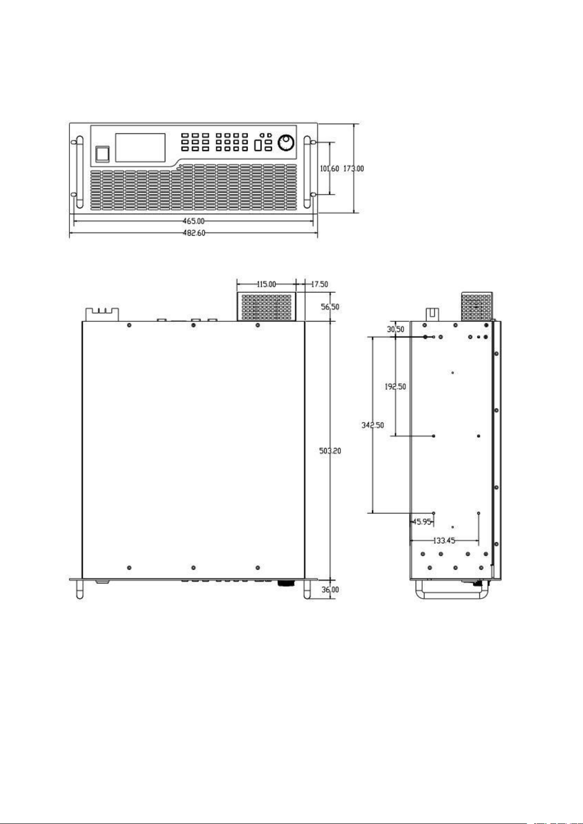
1.3 Dimension diagram...............................................................................................................................- 7 -
1.3.1 Model of 2kW, 3.2kW...........................................................................................................................- 7 -
1.3.2 Model of 6.5kW..................................................................................................................................... - 8 -
1.4 Model Naming..........................................................................................................................................- 9 -
1.5 Specification sheet.............................................................................................................................. - 9 -
2. Quick Guide...............................................................................................................................................................- 12 -
2.1 Checking Goods................................................................................................................................... - 12 -
2.2 Front Panel..............................................................................................................................................- 13 -
2.3 Keyboard..................................................................................................................................................- 13 -
2.4 Screen Display......................................................................................................................................- 15 -
2.5 Rear Panel...............................................................................................................................................- 16 -
2.6 Installing.................................................................................................................................................. - 17 -
2.6.1 Preparation For Use.......................................................................................................................... - 17 -
2.6.2 Requirements of Input Power......................................................................................................... - 17 -
2.6.3 Power ON Self Check........................................................................................................................- 17 -
2.7 Connection..............................................................................................................................................- 18 -
2.7.1 Input Connection...............................................................................................................................- 18 -
2.7.2 Input Connection for Multiple Power Supplies............................................................................ - 18 -
2.7.3 Output Connection........................................................................................................................... - 19 -
2.7.4 V-Sensing Connection...................................................................................................................... - 19 -
2.7.5 Analog Interface................................................................................................................................ - 20 -
3. FUNCTION INTRODUCTION..............................................................................................................................- 22 -
3.1 Local & remote operation mode.................................................................................................- 22 -
3.2 Menu Layout...........................................................................................................................................- 22 -
3.2.1 Set Menu............................................................................................................................................ - 22 -
3.2.2 Edit Menu........................................................................................................................................... - 24 -
3.2.3 About Menu....................................................................................................................................... - 24 -
3.3 Switch Power Supply Output Mode...........................................................................................- 24 -
3.4 Turn ON/OFF Power Supply Output........................................................................................... - 25 -
3.5 Setting Voltage, Current................................................................................................................. - 25 -
3.6 Save and Recall................................................................................................................................... - 26 -
3.6.1 Save Operation.................................................................................................................................. - 26 -
3.6.2 Recall Operation................................................................................................................................ - 26 -
3.6.3 Shortcut Recall...................................................................................................................................- 26 -
3.7 Output Setting.......................................................................................................................................- 27 -
3.7.1 Voltage/Current Limit Set................................................................................................................ - 27 -
3.7.2 DC_ON Set..........................................................................................................................................- 27 -
3.7.3 Voltage Slew Rate............................................................................................................................. - 28 -

____________________________________________________________________________
- 5 -
3.7.4 Current Slew Rate..............................................................................................................................- 29 -
3.7.5 CV/CC Priority Start function...........................................................................................................- 29 -
3.8 Protection................................................................................................................................................- 30 -
3.9 External Analog Programming.....................................................................................................- 32 -
3.9.1 External Analog Programming Connection...................................................................................- 33 -
3.9.2 External Analog Programming Reference Voltage...................................................................... - 33 -
3.10 External Control................................................................................................................................ - 34 -
3.11 Master-slave Parallel and Serial Operation....................................................................... - 35 -
3.11.1 Output Connection......................................................................................................................... - 35 -
3.11.2 Communication Connection..........................................................................................................- 36 -
3.11.3 Slave Setting.................................................................................................................................... - 37 -
3.11.4 Master Setting................................................................................................................................. - 38 -
3.11.5 Parallel/Serial Operation V/I Setting............................................................................................ - 38 -
3.11.6 Parallel/Serial Operation Protection.............................................................................................- 39 -
3.12 Constant Power Output (CP) Setting.....................................................................................- 40 -
3.13 SEQ (Sequence) Output Setting............................................................................................... - 40 -
3.14 System Configuration.....................................................................................................................- 43 -
3.14.1 Power Save.......................................................................................................................................- 43 -
3.14.2 Power Output.................................................................................................................................. - 43 -
3.14.3 Shortcut Recall.................................................................................................................................- 44 -
3.14.4 Remote Communication Address.................................................................................................- 44 -
3.14.5 Baud Rate and Parity Set................................................................................................................- 44 -
3.14.6 Sound................................................................................................................................................- 44 -
3.14.7 Language..........................................................................................................................................- 44 -
4. COMMUNICATION INTRODUCTION..............................................................................................................- 45 -
4.1 Communication Interface...............................................................................................................- 45 -
4.1.1 RS232.................................................................................................................................................. - 45 -
4.1.2 LAN......................................................................................................................................................- 45 -
4.1.3 Voltage, Current Acquisition Speed............................................................................................... - 46 -
4.2 Communication Protocol................................................................................................................ - 46 -
5. TROUBLESHOOTING............................................................................................................................................ - 48 -
6. APPENDIX...................................................................................................................................................................- 49 -

FTP Series Programmable DC Power Supply Operation Manual
____________________________________________________________________________
- 6 -
1. General Description
1.1 Overview
FTP series programmable DC power supply is a high-performance DC power supply, with rated output
power 2/3.2/6.5kW, output voltage up to 1500V, current up to 240A. It has the advantages of wide range
output, low ripple noise, fast transient response, high resolution, high precision, voltage and current slew
rate settable. Moreover, the 40V and 80V model FTP can be configured with automotive waveform test
feature, compatible with ISO16750-2, VW80000 standards.
FTP series is the best choice for ATE system integration, laboratory test, vehicle equipment test,
superconducting test, motor test, battery charging simulation, voltage and current sensor calibration, laser
test and power supply, electronic product life cycle test and other applications.
1.2 Main features
■Output voltages: 40 V up to 1500 V;
■Output current: 3.5 A up to 240 A;
■Output power: 2 / 3.2 / 6.5 kW;
■Constant power output;
■Easy Master-Slave parallel or serial;
■Precision V & I measurement;
■High speed programming;
■1ms typical transient response;
■Programmable sequence;
■Voltage & current slew rate control;
■CV / CC priority;
■Foldback protection;
■Wide operating region for output;
■Remote sense compensation;
■Optional analog programming & monitoring interface;
■±OVP, ±OCP, ±OPP, OTP, ±LVP;
■Voltage limit, current limit;
■Standard LAN, RS232, optional GPIB interface;
■SCPI and ModBus RTU protocol;
■TFT color LCD display.

____________________________________________________________________________
- 7 -
1.3 Dimension diagram
1.3.1 Model of 2kW, 3.2kW

FTP Series Programmable DC Power Supply Operation Manual
____________________________________________________________________________
- 8 -
1.3.2 Model of 6.5kW

____________________________________________________________________________
- 9 -
1.4 Model Naming
1.5 Specification sheet
Specification table 1
Model
FTP020-40-120
FTP020-50-110
FTP020-80-60
FTP020-120-40
FTP020-160-30
FTP020-300-16
Voltage
0~40V
0~50V
0~80V
0~120V
0~160V
0~300V
Current
0~120A
0~110A
0~60A
0~40A
0~30A
0~16A
Power
2000W
Model
FTP032-40-120
FTP032-50-110
FTP032-80-60
FTP032-120-40
FTP032-160-30
FTP032-300-16
Voltage
0~40V
0~50V
0~80V
0~120V
0~160V
0~300V
Current
0~120A
0~110A
0~60A
0~40A
0~30A
0~16A
Power
3200W
Model
FTP065-40-240
FTP065-50-220
FTP065-80-120
FTP065-120-80
FTP065-160-60
FTP065-300-32
Voltage
0~40V
0~50V
0~80V
0~120V
0~160V
0~300V
Current
0~240A
0~220A
0~120A
0~80A
0~60A
0~32A
Power
6500W
Voltage programming
Resolution
16Bits
Accuracy
0.1%+0.1%F.S.
Current programming
Resolution
16Bits
Accuracy
0.1%+0.3%F.S.
0.1%+0.2% F.S.
External analog programming
Control voltage
0~5V or 0~10V corresponds to 0~100%F.S.
Voltage accuracy
0.2%F.S.
Current accuracy
0.5%F.S.
Analog output
Output voltage
0~100%F.S. corresponds to 0~10V.
Voltage accuracy
0.5%F.S.
Current accuracy
0.5%F.S.
Line regulation
Voltage
0.01%+0.01%F.S.
Current
0.02%+0.01%F.S.

FTP Series Programmable DC Power Supply Operation Manual
____________________________________________________________________________
- 10 -
Load regulation
Voltage
0.01%+0.05%F.S.
0.01%+0.01%F.S.
Current
0.02%+0.1%F.S.
Voltage measurement
Resolution
16Bits
Accuracy
0.1%+0.1%F.S.
Current measurement
Resolution
16Bits
Accuracy
0.1%+0.3%F.S.
0.1%+0.2%F.S.
Ripple noise
Ripple Vpp
60mV
70mV
80mV
80mV
100mV
100mV
Ripple Vrms
20mV
20mV
20mV
20mV
40mV
40mV
Rise slew rate
Voltage
5V/ms(max)
Current
2A/ms(max)
OVP Setting
Range
0~110%F.S.
Accuracy
1%F.S.
Transient
Typical 1ms
Efficiency
0.9(Typical)
Parallel/Serial
Support master-slave parallel and serial operation
Communication
RS232 and LAN
AC input
190VAC~265VAC, 47Hz~63Hz, PF: 0.98(Typical)
Operation temp
0℃~40℃
Storage temp
-20℃~70℃
Altitude
<2000m
Dimension
430(W)×88(H)×453(D)mm (2kW&3.2kW model); 430(W)×177(H)×503(D)mm (6.5kW model)
Weight
15kg(2kW&3.2kW model); 29kg(6.5kW model)
Specification table 2
Model
FTP020-400-12
FTP020-600-8
FTP020-800-8
FTP020-1000-5
FTP020-1200-5
FTP020-1500-3.5
Voltage
0~400V
0~600V
0~800V
0~1000V
0~1200V
0~1500V
Current
0~12A
0~8A
0~8A
0~5A
0~5A
0~3.5A
Power
2000W
Model
FTP032-400-12
FTP032-600-8
FTP032-800-8
FTP032-1000-5
FTP032-1200-5
FTP032-1500-3.5
Voltage
0~400V
0~600V
0~800V
0~1000V
0~1200V
0~1500V
Current
0~12A
0~8A
0~8A
0~5A
0~5A
0~3.5A
Power
3200W
Model
FTP065-400-24
FTP065-600-16
FTP065-800-16
FTP065-1000-10
FTP065-1200-10
FTP065-1500-7
Voltage
0~400V
0~600V
0~800V
0~1000V
0~1200V
0~1500V
Current
0~24A
0~16A
0~16A
0~10A
0~10A
0~7A
Power
6500W
Voltage programming
Resolution
16Bits

____________________________________________________________________________
- 11 -
Accuracy
0.1%+0.1%F.S.
Current programming
Resolution
16Bits
Accuracy
0.1%+0.2% F.S.
External analog programming
Control voltage
0~5V or 0~10V corresponds to 0~100%F.S.
Voltage accuracy
0.2%F.S.
Current accuracy
0.5%F.S.
Analog output
Output voltage
0~100%F.S. corresponds to 0~10V.
Voltage accuracy
0.5%F.S.
Current accuracy
0.5%F.S.
Line regulation
Voltage
0.01%+0.01%F.S.
Current
0.02%+0.01%F.S.
Load regulation
Voltage
0.01%+0.01%F.S.
Current
0.02%+0.1%F.S.
Voltage measurement
Resolution
16Bits
Accuracy
0.1%+0.1%F.S.
Current measurement
Resolution
16Bits
Accuracy
0.1%+0.2%F.S.
Ripple noise
Ripple Vpp
300mV
300mV
500mV
450mV
500mV
700mV
Ripple Vrms
60mV
60mV
80mV
80mV
120mV
150mV
Rise slew rate
Voltage
5V/ms(max)
Current
2A/ms(max)
OVP Setting
Range
0~110%F.S.
Accuracy
1%F.S.
Transient
Typical 1ms
Efficiency
0.9(Typical)
Parallel/Serial
Support master-slave parallel and serial operation
Communication
RS232 and LAN
AC input
190VAC~265VAC, 47Hz~63Hz, PF: 0.98(Typical)
Operation temp
0℃~40℃
Storage temp
-20℃~70℃
Altitude
<2000m
Dimension
430(W)×88(H)×453(D)mm(2kW&3.2kW model); 430(W)×177(H)×503(D)mm(6.5kW model)
Weight
15kg(2kW&3.2kW model); 29kg(6.5kW model)

FTP Series Programmable DC Power Supply Operation Manual
____________________________________________________________________________
- 12 -
2. Quick Guide
2.1 Checking Goods
Upon reception of the power supply, please examine the equipment according to procedures stipulated as below.
(1) Check if there is damage during transportation.
Contact authorized dealer or Faithtech after-sale service immediately if the packing or protective cushion is
severely damaged.
-----------------------------------------------------------------------------------------------------------------------
Do not return the instrument without obtaining prior approval from Faithtech.
-----------------------------------------------------------------------------------------------------------------------
(2) Check for the accessories.
Make sure you have received the following accessories along with the power supply:
Table 2-1 Accessories Explanation
Accessory
QTY
Explanation
AC input power cable
1 PCS
*10A(2kW) / 16A(3.2kW) 3-core power cable
RS232 communication cable
1 PCS
For connecting PC and RS232 port
LAN communication cable
1 PCS
For connecting PC and LAN port
Protective cover
1 PCS
For output protection
User Manual
1 PCS
Installing and operation info
CD Disk
1 PCS
Tech info
Warranty and after-sale info
1 PCS
Warranty and after-sale info
*6.5kW model does not come with AC input cable.
Contact authorized dealer or Faithtech after-sale service immediately if there is damage or miss.
(3) Check for the power supply unit.
Contact authorized dealer or Faithtech after-sale service immediately if the power supply case is damaged or
working abnormally.
(4) Cleaning.
If you need to clean the casing of the machine, please wipe it gently with a dry cloth or a slightly damp cloth. Do
not wipe the inside of the machine.
-----------------------------------------------------------------------------------------------------------------------
Turn off the power supply before cleaning.
-----------------------------------------------------------------------------------------------------------------------

____________________________________________________________________________
- 13 -
2.2 Front Panel
Figure 2-1 FTP Front Panel
①Power switch
②TFT color screen
③Keyboard
④Rotary knob
2.3 Keyboard
Figure 2-2 FTP keyboard
Table 2-2 Key Function Descriptions
Button
Description
Move the cursor position, or increase/decrease numeric number
Go to voltage/current output interface
Go to sequence output interface
Go to constant power output interface

FTP Series Programmable DC Power Supply Operation Manual
____________________________________________________________________________
- 14 -
Switch to local operation mode from remote control mode
Save the settings of the static output to internal memory.
Go to main menu.
Lock/Unlock the keyboard
Recall the saved settings from internal memory.
Clear the occurred protection and warning messages.
to
and
Input numeric numbers and decimal point
Each press clears one digit of your numeric or decimal input.
Control the cursor to move between digits when setting parameters. In menu navigation,
used for navigating and selecting the menu item.
Enter into set item, or confirm input and exit set item.
Exit set item or current menu.
Turn on/off power supply output.

____________________________________________________________________________
- 15 -
2.4 Screen Display
Figure 2-3 MAIN PAGE Display
①Specification info of the power supply;
②Parameters setting area;
③Status prompt area;
④Readback voltage, current, etc. parameters display area;
About specification info:
Displays the rated voltage, rated current, rated power of the power supply;
About V, I parameters display area:
Displays readback voltage, current, power, measurement result etc.. However, the actual displayed information
varies, for example, in voltage/current static output mode, the area displays output voltage, current and power; in
sequence test mode, the area displays output voltage, current, sequence current steps and sequence cycle times.
About Status prompt area:
Protection occurred: Blank (no protection occurred), OVP, OCVP, OCP, OPP, OTP, LVP, RVP, etc..
protections occurred;
Output mode indicator: CV, CC, CP, Off;

FTP Series Programmable DC Power Supply Operation Manual
____________________________________________________________________________
- 16 -
2.5 Rear Panel
Figure 2-4 FTP Rear Panel
Item
Name
Description
1
DC Output
The output terminals of the DC Power Supply.
2
Remote/Local V-SENSE
This connector compensates for any voltage drop
generated by the cable resistance. Be sure to connect the
remote sense connector “+” to the positive output terminal
and the “–” connector to the negative output terminal. Do
not reverse the connections.
3
Parallel Current Share In
For master-salve parallel operation
4
Parallel Current Share Out
For master-salve parallel operation
5
RS485
For master-salve parallel or serial operation
6
RS232
The remote controller uses the RS232 connector to connect
to a PC for remote operation.
7
LAN
The remote controller uses the LAN connector to connect to
a PC for remote operation.
8
Analog interface
This interface has the functions of analog programming
input, voltage/current monitoring output, external control,
power supply status and work mode indication.
9
AC INPUT
Single phase AC INPUT

____________________________________________________________________________
- 17 -
2.6 Installing
2.6.1 Preparation For Use
(1) Ensure the Power Supply is connected to the AC line input that meets the specification.
(2) The instrument must be installed in an area with good air circulation to avoid the internal temperature getting
too high.
(3) For indoor use only, ambient temperature 0°C to 40°C.
2.6.2 Requirements of Input Power
Please pay attention to the following items for FTP series power supply input connection:
①Single phase AC input: 190VAC~265VAC, 47~63Hz;
②Ensure reliable grounding;
③The AC power cord temperature resistance is greater than 85℃;
④Please refer to "Table 6-1 Recommended Wire Diameters for Cables" for the selection of input wire diameters
to avoid potential safety hazards due to thinner wire diameters.
----------------------------------------------------------------------------------------------------------------------------
1. To protect the operator, the wire connected to the GND terminal must be connected to
the earth. Under no circumstances shall this DC Power Supply be operated without an
adequate ground connection.
2. Installation of the power cord must be done by a professional and compliant with local
electrical codes.
----------------------------------------------------------------------------------------------------------------------------
2.6.3 Power ON Self Check
When powered on, the power supply will conduct self check, the check process and results will be displayed on
the screen, such as below:
Figure 2-5 FTP Power ON Self Check
The power supply will enter MAIN PAGE if all checking results are OK.
If there is FAULT during power supply power on self check, please contact authorized Faithtech agent or Faithtech
after-sale service.

FTP Series Programmable DC Power Supply Operation Manual
____________________________________________________________________________
- 18 -
2.7 Connection
2.7.1 Input Connection
The user connects the three-phase wire and the ground wire to the power supply input terminal as shown in
Figure 2-6. For the size of the wire diameter, please refer to "Table 6-1 Recommended Wire Diameter for Cables".
Figure 2-6 FTP Power supply Input Connection
----------------------------------------------------------------------------------------------------------------------------
1. To protect the operator, the wire connected to the GND terminal must be connected to
the earth. Under no circumstances shall this DC Power Supply be operated without an
adequate ground connection.
2. Installation of the power cord must be done by a professional and compliant with local
electrical codes.
----------------------------------------------------------------------------------------------------------------------------
2.7.2 Input Connection for Multiple Power Supplies
If multiple models are connected to the grid, it is recommended to distribute the access points in a balanced
manner as shown in the figure below.
Figure 2-7 Input Connection of multiple FTP Models
This manual suits for next models
18
Table of contents
Other Faithtech Power Supply manuals