FOR-A UFH-70VDA User manual

UFH-70VDA
Video Distribution Amplifier
1st Edition
OPERATION
MANUAL


Upon Receipt
Unpacking
UFH-70VDA units and their accessories are fully inspected and adjusted prior to shipment.
Operation can be performed immediately upon completing all required connections and
operational settings.
Check your received items against the packing lists below.
ITEM QTY REMARKS
UFH-70VDA 1
Operation Manual 1
Check
Check to ensure no damage has occurred during shipment. If damage has occurred, or items
are missing, inform your supplier immediately.

Table of Contents
1. Prior to Starting........................................................................................................................... 1
1-1. Welcome ............................................................................................................................ 1
1-2. Features ............................................................................................................................. 1
1-3. About This Manual.............................................................................................................. 1
2. Panel Descriptions ..................................................................................................................... 2
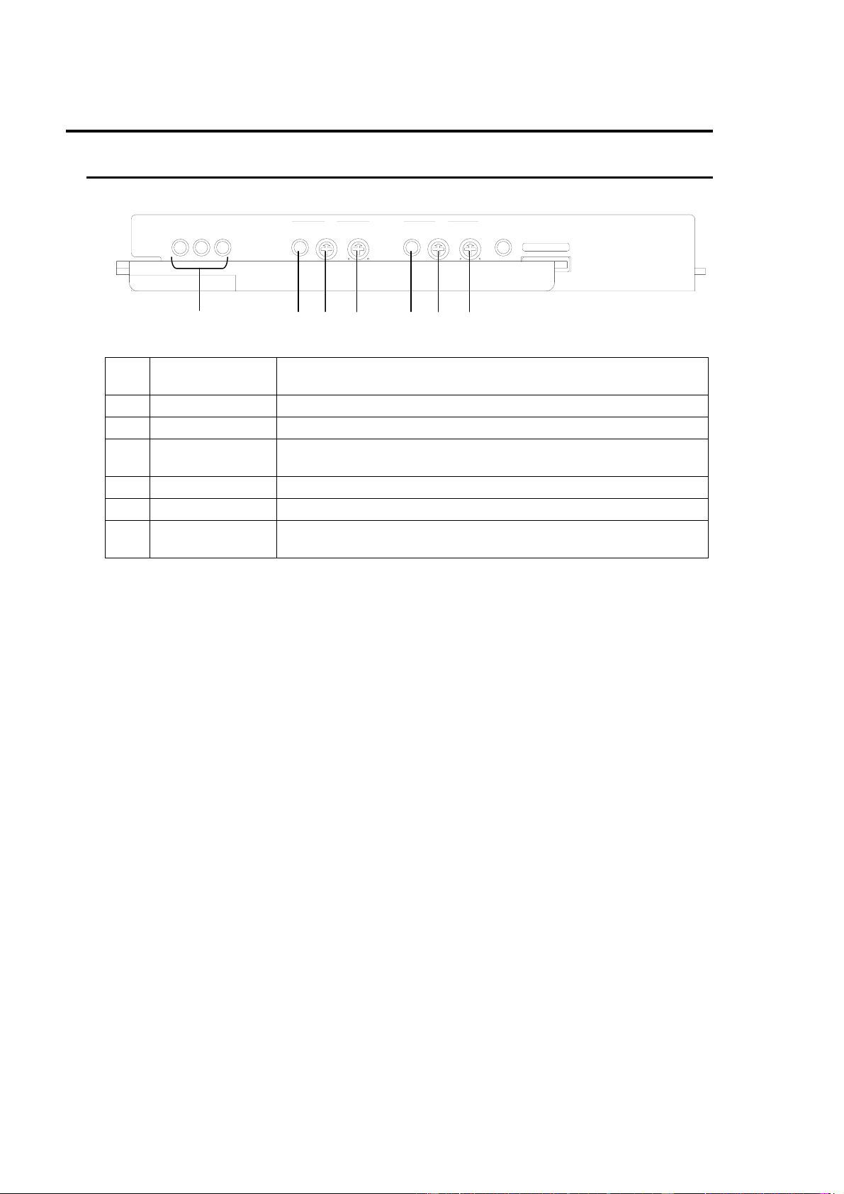
2-1. Front Panel......................................................................................................................... 2
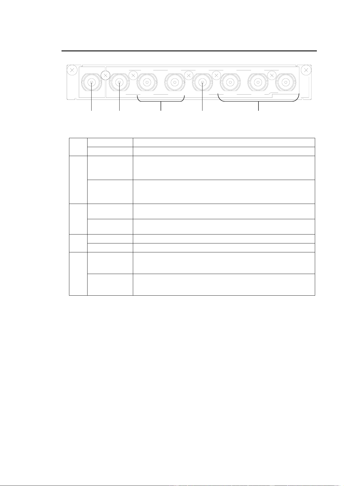
2-2. Rear Panel ......................................................................................................................... 3
3. Connection ................................................................................................................................. 4
4. Block Diagram............................................................................................................................ 5
5. Operation ................................................................................................................................... 6
5-1. Powering On....................................................................................................................... 6
5-2. Internal Settings ................................................................................................................. 7
5-2-1. Switch Locations ........................................................................................................ 7
5-2-2. Operation Mode(S1, S201).................................................................................... 7
5-2-3. OUT 1 THRU (OUT A1) Output Mode (S101, S102) .................................................. 8
5-2-4. Clamp Settings (S103, S104 / S203, S204) ............................................................... 9
6. Specifications and Dimensions................................................................................................. 10
6-1. Specifications ................................................................................................................... 10
6-2. Dimensions ...................................................................................................................... 11

1
1. Prior to Starting
1-1. Welcome
Congratulations! By purchasing UFH-70VDA Video Distribution Amplifier you have entered the
world of FOR-A and its many innovative products. Thank you for your patronage and we hope
you will turn to FOR-A products again and again to satisfy your video and audio needs.
FOR-A provides a wide range of products, from basic support units to complex system
controllers, which have been increasingly joined by products for computer video based systems.
Whatever your needs, talk to your FOR-A representative. We will do our best to be of continuing
service to you.
1-2. Features
The UFH-70VDA is module type analog video distributor that can be installed in the UFH frame.
It can distribute one input into seven outputs or two systems of one input into three outputs.
Video gain control available on the front panel
Cable compensation up to 300m (when BNC 5C-2V, RG-11A/U or equivalent cable used).
Input signal detection feature
Enables setting of 1 input with 7-way distribution or two systems of 1 input with 3-way
distribution.
DC clamp and AC or DC coupled outputs selectable.
Possible to loop through Input A by internal setting
1-3. About This Manual
This manual is intended to help the user easily operate this product and make full use of its
functions during operations. Before connecting or operating your unit, read this operation
manual thoroughly to ensure you understand the product. After reading, it is important to keep
this manual in a safe place and available for reference.

2
2. Panel Descriptions
2-1. Front Panel
(1) Power Indicator Lights up when the power supply circuit on the board is operated
properly.
(2) INPUT Lights up when an analog composite signal is input.
(3) GAIN Used to adjust the video gain.
(4) COMPEN Used to adjust the cable compensation in a range from 0 to
300m (when 5C2V compatible cable used).
(5) INPUT (*1) Lights up when an analog composite signal is input.
(6) GAIN (*1) Used to adjust the video gain.
(7) COMPEN (*1) Used to adjust the cable compensation in a range from 0 to
300m (when BNC 5C-2V, RG-11A/U or equivalent cable used).
(*1) Available in dual channel mode (2 systems of 1 input into 3 outputs).
(1) (2) (3) (4) (5) (6) (7)
UFH-70VDA
+3.3V +5V -5V INPUT GAIN COMPEN
AINPUT GAIN (OPTION)
B
300
0
300
0UFH-70VDA
COMPEN INTERFACE

3
2-2. Rear Panel
VIDEO IN Used as a video input in single channel mode.
(1) IN A Used as a video input (Ch A) in dual channel mode.
OUT 1THRU
Used as a video output in single channel mode.
This connector can be used as a loopthrough connector (VIDEO
IN/IN A signal loopthrough) by internal settings.
(2)
OUT A1
Used as a video output (Ch A) in dual channel mode.
This connector can be used as a loopthrough connector (VIDEO
IN/IN A signal loopthrough) by internal settings.
OUT2,
OUT3 Used as a video output in single channel mode.
(3) OUT A2,
OUT A3 Used as a video output (Ch A) in dual channel mode.
OUT4 Used as a video output in single channel mode.
(4) IN B Used as a video input (Ch B) in dual channel mode.
OUT5,
OUT6,
OUT7 Used as a video output in single channel mode.
(5) OUT B1,
OUT B2,
OUT B3 Used as a video output (Ch B) in dual channel mode.
INAOUTA1OUTA2OUTA3INBOUTB1OUTB2OUTB3
UFH-70VDA
OUT1/THRU
VIDEOINOUT2OUT3OUT4OUT5OUT6OUT7
(3)(1) (2) (4) (5)

4
3. Connection
Connect the unit to other equipment in the total system as shown in the figure below.
Note that before installing the UFH-70VDA into the System Frame, you should thoroughly read the
operation manual for the System Frame where you will be installing. Turn off the System Frame
and other equipment before connection.
(1)Single channel mode (1 input into 7 outputs)
(2)Dual channel mode (2 systems of 1 input into 3 outputs)
Composite signal
(Ch A) IN A OUT A1
OUT A2
OUT A3
UFH-70VDA
UFH Frame
OUT B1
OUT B2
OUT B3
Composite signals
(Ch A)
IN B
Composite signals
(Ch B)
Composite signal
(Ch B)
VIDEO IN OUT 1
OUT 2
OUT 3
OUT 4
UFH-70VDA
OUT 5
OUT 6
OUT 7
UFH Frame
Composite signal
Composite signals

5
4. Block Diagram
A block diagram of the UFH-70VDA is shown below:
VIDEO IN, IN A
OUT 1 / THRU, OUT A1
OUT 2, OUT A2
OUT 3, OUT A3
OUT 4, IN B
OUT 5, OUT B1
OUT 6, OUT B2
OUT 7, OUT B3
・Gain Adjust
・Cable Compensation
・Input Detection
・Gain Adjust
・Cable Compensation
・Input Detection

6
5. Operation
5-1. Powering On
1) Loosen the screws on both side of the front panel of UFH frame, and then grasp the knob
screws to pull them out.
2) Turn on the power switches.
SYSTEM FRAM E
GENLOCK
12FAN
ALARM
TEMP DC PO W UFH-112
POWER
1
2
POWER GENLOCK
12FAN
ALARM
TEMP DC PO W

7
5-2. Internal Settings
The following settings can be made via the front module of the UFH-70VDA.
Switch settings must be made prior to installing any module to the UFH frame.
5-2-1. Switch Locations
5-2-2. Operation Mode(S1, S201)
The S1 and S201 switches are used to select between single channel (1 input into 7 outputs)
and dual channel (2 systems of 1 input into 3 outputs) modes.
The factory default setting is A position (single channel mode).
When changing the mode, be sure to set the S1 and S201 switches to the same operation mode.
The system will not operate properly if the settings do not match.
Switch Setting
S1 S201 Operation Mode
A position A position Single channel mode
A/B position A/B position Dual channel mode
S102
S101S201
S1
S103
S104
S204
S203
S201
S201
S1
A
A/B
MODE SEL 1/2
S1 A
A/B
MODE SEL 2/2

8
5-2-3. OUT 1 THRU (OUT A1) Output Mode (S101, S102)
The S101 and S102 switches are used to set OUT 1 THRU (OUT A1) output mode to
distribution or loopthrough (VIDEO IN / IN A signal loopthrough). When changing the mode,
be sure to set the S101 and S102 switches to the same output mode. The system will not
operate properly if the settings do not match.
The factory default setting is distribution (S101: AMP OUT, S102: 75 Ω).
Switch Setting
S101 S102 Output Mode
AMP OUT position 75 Ωposition Distribution
THRU position Hi position Loopthrough
VIDEO IN, IN A
OUT 1 / THRU, OUT A1
75 Ω
S102
S101
S102
S101
S101 THRU
AMP OUT
OUT / THRU SEL
S102 Hi
75 Ω
75 Ω/ Hi

9
5-2-4. Clamp Settings (S103, S104 / S203, S204)
The S103, S104, S203, and S204 switches are used to enable clamp ON/OFF for the video
output signal.
The factory default settings are as follows:
S103, S203: CLAMP
S104, S204: DC
Ch B Clamp Setting in Dual Channel Mode
Switch Setting
S203 S204 Coupling / Clamp
DC position
CLAMP position AC position DC clamp
DC position DC coupled
DC/AC position AC position AC coupled
Single Channel Mode / Ch A Clamp Setting in Dual Channel Mode
Switch Setting
S103 S104 Coupling / Clamp
DC position
CLAMP position AC position DC clamp
DC position DC coupled
DC/AC position AC position AC coupled
S204
S203
DC
S203
CLAMP
DC/AC
COUPLING
AC
S204
S103
S104
DC
S103
CLAMP
DC/AC
COUPLING
AC
S104

10
6. Specifications and Dimensions
6-1. Specifications
Video Inputs
(insternally selectable)
・Analog composite, 1.0V (p-p), 75Ω, or high impedance loopthrough
selectable, BNC, 1 input
・Analog composite, 1.0V (p-p), 75Ω, BNC, 2 inputs
Video Outputs
(insternally selectable)
・Analog composite, 1.0V (p-p), 75Ω, BNC, 7 outputs
(6 outputs in loopthrough mode)
・Analog composite, 1.0V (p-p), 75Ω, BNC, 2 systems of 3 outputs
(2 outputs for OUT A and 3 outputs for OUT B in loopthrough mode)
Frequency Response 100kHz-6MHz within ±0.2dB
DG/DP 0.5% / 0.5° (APL 50%)
Gain Range -3.0dB to +3.0dB for input
Cable Length
Compensation
300m max. (when BNC 5C-2V, RG-11A/U or equivalent cable used)
Clamp Clamp ON/OFF internally selectable
AC coupled / DC coupled selectable when set to CLAMP OFF.
Temperature 10°C - 40°C
Humidity 30% - 90% (no condensation)
Power +24VDC (supplied with UFH frame)
Power Consumption 2.2VA (2.2W)
Weight 1.0 kg
Dimensions Front module: 138.5 (W) x 400 (D) mm
Rear module: 141 (W) x 101 (D) mm
Required slot 1 slot

11
6-2. Dimensions
(All dimensions in mm.)
87.8 379.5
UFH -70V D A
UFH-70VDA
+3.3 V +5V -5 V INPUT GAIN COMPEN
AINPUT GAIN (OPTION)
B
30003000
VIDEOINOUT1/THRUOUT2OUT3OUT4OUT5OUT6OUT7
INAOUTA1OUTA2OUTA3INBOUTB1OUTB2OUTB3
UFH-70VDA
COMPE N INTE RFAC E
141
20
(101) (400)
I/F CARD (Option)


Warning
This equipment has been tested and found to comply with the limits for a
Class A digital device, pursuant to Part 15 of FCC Rules. These limits are
designed to provide reasonable protection against harmful interference
when the equipment is operated in a commercial environment. This
equipment generates, uses, and can radiate radio frequency energy and,
if not installed and used in accordance with the instruction manual, may
cause harmful interference to radio communications. Operation of this
equipment in a residential area is likely to cause harmful interference, in
which case the user will be required to correct the interference at his own
expense.

09/29/2009 Printed in Japan
FOR-A COMPANY LIMITED
Head Office : 3-8-1 Ebisu, Shibuya-ku, Tokyo 150-0013, Japan
Overseas Division Phone: +81 (0)3-3446-3936, Fax: +81 (0)3-3446-1470
Japan Branch Offices : Osaka/Okinawa/Fukuoka/Hiroshima/Nagoya/Sendai/Sapporo
R&D/Production : Sakura Center/Sapporo Center
FOR-A America Corporate Office
11125 Knott Ave., Suite #A, Cypress, CA 90630, USA
Phone: +1 714-894-3311 Fax: +1 714-894-5399
FOR-A America East Coast Office
Two Executive Drive, Suite 670, Fort Lee Executive Park, Fort Lee NJ 07024, USA
Phone: +1 (201) 944-1120 Fax : +1 (201) 944-1132
FOR-A America Distribution & Service Center
2400 N.E. Waldo Road, Gainesville, FL 32609, USA
Phone: +1 352-371-1505 Fax: +1 352-378-5320
FOR-A Corporation of Canada
346A Queen Street West, Toronto, Ontario M5V 2A2, Canada
Phone: +1 416-977-0343 Fax: +1 416-977-0657
FOR-A Latin America & the Caribbean
5200 Blue lagoon Drive,
Suite 760, Miami, FL 33126, USA
Phone: +1-305-931-1700 Fax: +1-305-264-7890
FOR-A UK Limited
UNIT C71, Barwell Business Park, Leatherhead Road, Chessington Surrey, KT9 2NY, UK
Phone: +44 (0)20-8391-7979 Fax: +44 (0)20-8391-7978
FOR-A Italia S.r.l.
Viale Europa 50 20093, Cologno Monzese (MI), Milan, Italy
Phone: +39 02-254-3635/6 Fax: +39 02-254-0477
FOR-A Corporation of Korea
801 Dangsan Bld., 53-1 Dangsan-Dong, Youngdeungpo-Gu, Seoul 150-800, Korea
Phone: +82 (0)2-2637-0761 Fax: +82 (0)2-2637-0760
FOR-A China Limited
708B Huateng Building, No. 302, 3 District, Jinsong, Chaoyang, Beijing 100021, China
Phone: +86 (0)10-8721-6023 Fax: +86 (0)10-8721-6033
*The contents of this manual are subject to change without notice.
Table of contents
Other FOR-A Amplifier manuals

FOR-A
FOR-A UFM-15VDA User manual

FOR-A
FOR-A USF-1040VEA User manual

FOR-A
FOR-A UFH-70ADA User manual

FOR-A
FOR-A DDA-106 User manual

FOR-A
FOR-A USF-1053DDA User manual

FOR-A
FOR-A USF-111DDA-12G User manual

FOR-A
FOR-A USF-105DDA-12G User manual

FOR-A
FOR-A UFM-14DADA User manual

FOR-A
FOR-A ADA+205A User manual

FOR-A
FOR-A USF-1053DDA User manual