FALK QUADRIVE JR User manual

QUADRIVE OWNERS
PRICE $2.00
PN - 2109326
Manual
CAUTION!
Drives are shipped
without oil.
Sizes 4407/M4407
thru 4608/M4608
JR, JF & JSC
®
a good name in industry

Gear Drive Identification
J is the basic drive identification. It can be furnished as a shaft mounted drive JR; a flange mounted drive JF; or a screw conveyor
drive JSC(Size 4407 only), as illustrated below. These unique identifiers, JR, JF, & JSC, are used throughout this manual to assist you
in identifying the instructions which apply to your drive arrangement.
NOTE: Use a TA-Taper bushing when mounting these drives on a straight driven shaft (Hollow shaft is taper bored).
The Falk Corporation, P.O. Box 492, Zip 53201-0492378-102
3001 W. Canal St., Zip 53208-4200, Milwaukee, WI USA Telephone: 414-342-3131August 2004
®
a good name in industry
Owners Manual •Quadrive Shaft Mounted Drives
(Page 2 of 56) Sizes 4407/M4407-4608/M4608
M 4 407 J 25
Size (Series)
Max Bushing Bore (4 7/16")
Drive Type
Ratio (Nominal 25:1)
Blank - Inch
M - Metric
+ TA Removal Tool
(JSC) Screw Conveyor Drive (Size 4407 only)
1) Drive With Seal Housing
2) Drive Shaft
+ Motor Mounts
+ Backstops
+ Cooling Fans
+ Vertical Breathers
+ Trough Ends
+ Thrust Plate Kits
+ V-Belt Guards
(JF) Flange Mounted Drive
1) Drive With Flange
TA Taper Bushing Optional
(JR) Shaft Mounted Drive
1) Basic Drive
2) Tie Rod
3) TA Taper Bushing

Introduction
WARRANTY — The Falk Corporation (the “Company”)
warrants that, for a period of one year from the date of
shipment, the product described herein will deliver successfully
its rated output as indicated on the nameplate, provided, it is
properly installed and maintained, correctly lubricated, and
operated in the environment and within the limits of speed,
torque or other load conditions for which it was sold. Such
product is expressly not warranted against failure or
unsatisfactory operation resulting from dynamic vibrations
imposed upon it by the drive system in which it is installed
unless the nature of such vibrations has been fully defined and
expressly accepted in writing by the Company as a condition of
operation.
WARNING: Consult applicable local and national safety
codes for proper guarding of rotating members.
Lock out power source and remove all external loads from
drive before servicing drive or accessories.
CAUTION: Do not weld the drive housing or accessories
without prior approval from The Falk Corporation. Welding on
the drive may cause distortion of the housing or damage to the
bearings and gear teeth. Welding without prior approval will
void the warranty.
DRIVE RATING — Operate the drive only within the
horsepower and output speed for which it was selected and
specified in Selection Guide 371-110 (M371-110) for the
application. Refer to the nameplate for drive size, ratio and
data.
FALK FACTORY REPAIR AND REBUILD — Falk wants to
continue to be your primary supplier, and extend our service
to you if your equipment is in the need of repair or
replacement.
We are able to furnish a fast turn-around on both the quotation
and rebuild. Nobody can do the job better than Falk. If you
need repair on Falk products...just ask.
Contact your local Falk Representative or Falk Distributor for
more information.
Table Of Contents
Section I — Drive Installation
Outfitting ········································4
Installation ·······································6
Lubrication ·······································8
Startup ·········································8
Section II — Drive Service & Repair
Preventive Maintenance ·································9
Stored & Inactive Drives ·································9
Removal Of Drive····································9
Drive Disassembly ...................................11
Identifying & Ordering Parts ...............................13
Recommended Spare Parts ...............................13
Parts List Of Falk Part Numbers .............................16
Bearing Cross Reference Numbers............................18
Seal Cross Reference Numbers .............................18
Section III — Drive Reassembly
Drive Reassembly ....................................19
Appendix
Appendix A: Lubrication Recommendations .......................26
Appendix B: Backstop Installation ............................29
Appendix C: TA Removal Tool .............................33
Appendix D: Motor Mount Installation..........................35
Appendix E: Vertical Standpipe Installation .......................37
Appendix F: Modification For Non-Standard Mounting Positions .............39
Appendix G: Parts Interchangeability 3000 vs 4000 Series ................41
Appendix H: Retaining Rings For Bushing Nuts and Thrust Plates &
Tooth Combinations For Vibrations Analysis.................43
Appendix J: Drive Shaft Recommendations for Tapered Drive Shafts ............44
Appendix K: Drive Shaft Recommendations Using TA Taper Bushing ............45
Appendix L: Drive Shaft Recommendations Using (TCB) Kit ................47
Appendix M: V-Belt Guard Installation ..........................49
Appendix N: Electric Fan Installation ..........................51
The Falk Corporation, P.O. Box 492, Zip 53201-0492 378-102
3001 W. Canal St., Zip 53208-4200, Milwaukee, WI USA Telephone : 414-342-3131 August 2004
®
a good name in industry
Quadrive Shaft Mounted Drives •Owners Manual
Sizes 4407/M4407-4608/M4608 (Page 3 of 56)
© The Falk Corporation, 1992, 2004. All Rights Reserved. Litho in U.S.A. FALK, EQUI-POISED, QUADRIVE, STEELFLEX, TA TAPER, and TORUS are registered trademarks.
The Contents of this manual are subject to change without notice or obligation. Information contained herein should be confirmed before placing orders.

Section I
Drive Installation
Outfitting
1. JR, JF & JSC — Find the desired mounting position in Figure
1 and install air vent and magnetic drain plug (packaged
separately with drive). Also note and/or mark the oil level
plug location OR in the case of a vertical mounting, refer to
Appendix E, for installation of vertical stand pipe. If the
mounting angle exceeds the limitations shown in Figure 1,
refer to Appendix E, to determine modifications necessary
within the limits illustrated therein. DO NOT fill drive with
lubricant at this time.
2. JR — The tapered bore hollow shaft is designed for use with
a TA Taper bushing for mounting on a driven shaft with a
straight outside diameter. The minimum and maximum
driven shaft engagement, dimension N in Figure 2, are
shown in Table 2. The minimum engagement is necessary
for full bushing engagement; the maximum engagement is
only if a thrust plate will be employed to remove the drive
from the driven shaft (See Appendix C for preferred removal
method). Shaft tolerances for driven shafts are shown in
Table 1.
The Falk Corporation, P.O. Box 492, Zip 53201-0492378-102
3001 W. Canal St., Zip 53208-4200, Milwaukee, WI USA Telephone: 414-342-3131August 2004
®
a good name in industry
Owners Manual •Quadrive Shaft Mounted Drives
(Page 4 of 56) Sizes 4407/M4407-4608/M4608
F
L
9O'CLOCK
F
F
L
L
D
D
D
12 O'CLOCK
6O'CLOCK
REPOSITION PLUGS TO
SUIT REQ'D. MOUNTING
3O'CLOCK
D=DRAIN
F=FILL&VENT
L=OILLEVEL
(HIGHEST
SIDE PLUG)
F
L
D
Figure 1 HORIZONTAL DRIVES
MIN. SPACE
REQUIRED FOR
V-BELT CLEARANCE
THRUST
PLATE
BORE
INPUT
SHAFT
MIN. SPACE
REQUIRED TO SPIN
BUSHING UNIT
BUSHING NUT
DRIVEN SHAFT
BEARING
SUPPORT
SHEAVE
N
Figure 2
STANDPIPE &
VENTED DIPSTICK STANDPIPE &
VENTED DIPSTICK
FILL FILL
DRAIN DRAIN
INPUT SHAFT DOWN INPUT SHAFT UP
±1°
MAX.
VERTICAL DRIVES
20 UP
MAX.
5 DOWN
MAX.
°
°
±10 MAX.°
ANGULAR LIMITS FOR HORIZONTAL MOUNTING
(ALL CLOCK POSITIONS)
TABLE 2 — N Dimension – Inches (mm) H
Drive Size Minimum Maximum
4407 8.38 (212,9) 12.40 (315,0)
4415 10.33 (262,4) 13.44 (341,4)
4507 10.66 (270,8) 14.53 (369,1)
4608 13.03 (331,0) 17.56 (446.0)
HThe minimum engagement is necessary for full bushing engagement, the
maximum engagement is only if a thrust plate will be employed to remove the
drive from the driven shaft.
TABLE1—DrivenShaft Tolerances – In
(mm)
Shaft Diameter Max Undersize
Over Thru
2.500 (63,5) 4.000 (101,6) .006 (0,15)
4.000 (101,6) 6.000 (152,4) .007 (0,18)
6.000 (152,4) 7.000 (177,8) .008 (0,20)

a) THIN WALL BUSHING (with keyway slot through the
bushing wall) — With the driven shaft keyway at the 12
o’clock position, slide bushing assembly onto the driven
shaft, nut end first, and position the keyway slot over the
shaft keyway. The bushing may have to be opened slightly
to assist in installation. Insert a screwdriver into the slot in
the bushing and very lightly pry open until the bushing
slides onto the shaft. Insert the drive key furnished with
the bushing into the shaft keyway. Proceed to Step 6.
b) THICK WALL BUSHING (with separate internal and
external keyways) — Insert the driven shaft key into the
driven shaft keyway. If the driven shaft has an
open-ended keyway, stake the keyway, Figure 3, to
prevent axial dislocation of the shaft key under operating
conditions. Slide the bushing assembly onto the driven
shaft. The bushing may have to be opened slightly to
assist in installation. Insert a screwdriver into the slot in
the bushing and very lightly pry open until the bushing
slides onto the shaft. Rotate the shaft so the external
keyway in the bushing is at the 12 o’clock position. Then
insert the drive key, furnished with the bushing, into the
keyway. Proceed to Step 6.
3. JSC(4407 only) — Remove the output cover from the input
side of the hollow shaft bore and save. Separate contents from
the drive shaft kit. Install thrust plate and retaining ring in the
hollow shaft, Figure 4. Insert key into drive shaft. Slide drive
shaft thru the seal housing into the hollow shaft and insert the
thrust plate fastener thru the thrust plate into the drive shaft.
Tighten fastener to 9500 lb-in. (1 073 Nm) Reinstall hollow
shaft cover. Continue outfitting based on the type of trough end
seal to be installed: (a) Waste Packing Seal; or (b) Lip Seal.
a) WASTE PACKING SEAL (Figure 5) — Pack seal housing
with waste packing and proceed to Step 4.
b) LIP SEAL (Figure 6) — Coat outside diameter of seal
with Permatex #3 or equivalent. Carefully slide seal over
drive shaft extension taking care to not damage the seal
lips. Drive seal into seal housing with the spring loaded
seal lip toward the trough end side of the seal housing,
flush with the seal housing. Proceed to Step 4.
The Falk Corporation, P.O. Box 492, Zip 53201-0492 378-102
3001 W. Canal St., Zip 53208-4200, Milwaukee, WI USA Telephone : 414-342-3131 August 2004
®
a good name in industry
Quadrive Shaft Mounted Drives •Owners Manual
Sizes 4407/M4407-4608/M4608 (Page 5 of 56)
THRUST
PLATE
RETAINING
RING KEY
SEAL HOUSING
HOLLOW SHAFT
Figure 4
Figure 3
DRIVE COVER
THRUST PLATE
RETAINING RING
THRUST PLATE
HOLLOW SHAFT
COVER
DRIVE SHAFT THRUST
PLATE FASTENER INSERT
DRIVE BASE
DRIVE SHAFT KEY
SEAL HOUSING
TROUGH END
TROUGH
END GASKET
TROUGH END
MOUNTING FASTENER
S
WASTE PACKING
DRIVE SHAFT
SEAL HOUSING FASTENERS
WITH LOCK WASHERS
Figure 5
DRIVE COVER
THRUST PLATE
RETAINING RING
THRUST PLATE
HOLLOW SHAFT
COVER
D
RIVE SHAFT THRUST
P
LATE FASTENER
INSERT
DRIVE BASE
DRIVE SHAFT KEY
SEAL HOUSING
TROUGH END
SEAL HOUSING FASTENERS
WITH LOCK WASHERS
TROUGH END
MOUNTING FASTENERS
LIP SEAL
DRIVE SHAFT
Figure 6
KEY
BUSHING
NUT
RETAINING
RING
BUSHING

4. JSC — Fasten the trough end to the seal housing using the flat
head hex socket cap screws included in the drive shaft kit. Refer
to Table 3 for torque value. Proceed to Step 6.
5. JF—(NOTE: If the driven shaft has not been machined to
Falk’s taper bore specifications per Falk Engineering
377-140 and a straight shaft is to be utilized, refer to Falk
Engineering 377-144 for instructions). If a backstop is
required and was Factory installed, remove the cover from
input end of hollow shaft bore and save. Install the thrust
plate and retaining ring in the hollow shaft (Refer to Figure
4). Installation of internal backstops NOT Factory installed,
may require removal of the mounting flange, Ref. #12, Page
14. Proceed to Step 6.
Installation
6. JR, JF & JSC — Refer to Figure 7 for recommended lifting
method. In order to sling JR & JF as illustrated, install the tie
rod fastener in the tie rod anchor brackets. Sling the drive
from the fastener as shown. For vertical installation, use (3)
eye bolts as illustrated. Eyebolt sizes are ½" (12,70 mm) for
4407/ thru 4507 and ¾” (19,05 mm) for 4608. DO NOT
remove sling until drive is secured to shaft. Before lifting the
drive into position, rotate the input shaft until the hollow
shaft keyway will be in position to line-up with the driven
shaft key. JF proceed to Step 11; JSC to Step 12.
7. JR — If the drive was received with a backstop installed, the
backstop must be temporarily removed to facilitate mounting
when the following conditions prevail:
Ratio J05 where rotation arrow indicates
Counter-Clockwise H.S. shaft rotation.
Ratio J09, J14, or J25 where rotation arrow indicates
Clockwise H.S. shaft rotation.
Refer to Section II, Figure 14 for Sizes 4407 thru 4507
and remove cover Ref. #19 and backstop Ref. #5A1. For
Size 4608, refer to Figure 15 and remove backstop Ref.
#5A. Proceed to Step 8.
8. JR — Lift the drive into position and slide onto the drive shaft
taking care that the driven shaft key seats into the hollow
shaft keyway. DO NOT hammer or use excessive force. Refer
to Figure 8 for installation of the tie rod. The exact position
of the tie rod may vary within the range shown. For tie rod
mountings other than shown, refer to Falk. If it is necessary
to shorten the tie rod, cut the excess from either threaded
end.
The support to which the clevis bracket is to be fastened
must sustain the torque reaction shown in Table 4. The
maximum load reaction through the tie rod occurs when the
tie rod is located in the extreme (40°) off angle position. The
magnitude of this force is reduced approximately 30% when
the tie rod is mounted in the preferred position shown in
Figure 8. Use Grade 5 fasteners to anchor the clevis
bracket; see Table 5 for the fastener diameter and tightening
torque.
The Falk Corporation, P.O. Box 492, Zip 53201-0492378-102
3001 W. Canal St., Zip 53208-4200, Milwaukee, WI USA Telephone: 414-342-3131August 2004
®
a good name in industry
Owners Manual •Quadrive Shaft Mounted Drives
(Page 6 of 56) Sizes 4407/M4407-4608/M4608
SLING AROUND
SEAL HOUSING
AND INPUT SHAFT
SLING FROM
LONG FASTENER
WITH NUT
Figure 7
TABLE 3 — (Size 4407 JSC) Trough End Fastener
Size (UNC) & Tightening Torques
lb-in (Nm) Non Lubricated
Fasteners
2.000 2.437 3.000 3.437
.625-11UNC .625-11UNC .750-10UNC .750-10UNC
2190 (247) 2190 (247) 3960 (447) 3960 (447)
TIE ROD
AND
TURNBUCKLE
CLEVIS
BRACKET
A
A
2°
2°
Figure 8 — Tie Rod Mounting Positions
6 O’Clock Mounting Position Shown
Drive Size A
4407 2°
4608 5°
TABLE 4 — Load Reaction Through Tie Rod
Drive Size 4407 4415 4507 4608
Load lbs H17900 21600 28600 33500
Load (N) H(79600) 96100 127200 149100
HLoad includes moment due to motor and motor mount with tie rod at
maximum angle.
TABLE 5 — Tie Rod Clevis Bracket Fastener
Tightening Torque
Drive
Size
Fastener
Size †
Tightening Torque – lb-in (Nm)
Steel
Foundation
Concrete
Foundation
4407 1.000-8UNC 6800 (768) 5600 (633)
4415 1.250-7UNC 12600 (1 424) 10400 (1 175)
4507 1.250-7UNC 12600 (1 424) 10400 (1 175)
4608 1.250-7UNC 12600 (1 424) 10400 (1 175)
†Grade 5 fasteners required.

Bolt the tie rod to both the clevis bracket and the drive
anchor bracket and tighten the bolts until seated against the
brackets. DO NOT bend the bracket as clearance between
the clevis brackets and tie rod is necessary.
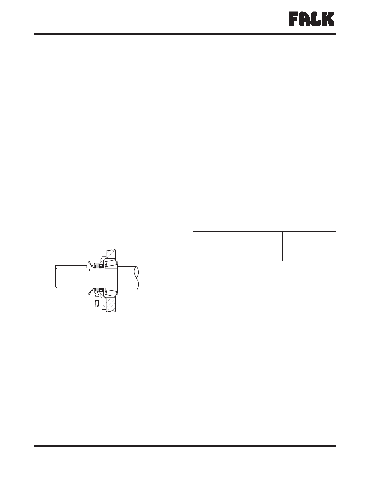
9. JR—Thread the bushing nut onto the hollow shaft one to
two turns. NOTE: The bushing nut threads have been coated
with an anti-seize compound at Falk. This compound should
not be removed. Before re-installing a previously used nut,
recoat the nut threads only with an anti-seize compound.
Keep the tapered surface of the bushing and hollow shaft
bore free from all anti-seize or lubricating compounds.
WARNING: Overtightening can fail the internal retaining
ring. (See Appendix H, for listing of retaining rings).
a) Preferred Method — Use a spanner (Table 6), chain or pipe
wrench to tighten the bushing nut to the torque value
indicated in Table 6. Tighten the setscrew on the bushing
nut.
b) Alternate Method (To be used when exact torque can not
be measured.) — Use a spanner (Table 6), chain or pipe
wrench to tighten the bushing nut just until the drive can
no longer be moved by hand axially on the driven shaft.
Loosen nut ONLY until it can be turned by hand but do
not unseat the taper. Retighten the nut hand tight. Now
mark a spot on the bushing nut. Next mark a spot on the
driven shaft 180° from the first mark. Use the spanner
wrench to tighten the nut until the two marks are aligned
i.e. one half turn. Tighten the setscrew on the bushing
nut.
10. JR — Install backstop, motor mount, motor, sheaves
(Mount sheaves as close to the drive and motor housing
as possible), belts and guard. Refer to Appendix D for
instructions.
11. JF (Using tapered drive shaft) — Put key into the driven
shaft. Lift drive into position and slide onto the driven shaft
taking care that the driven shaft key seats into the hollow
shaft keyway. DO NOT hammer or use excessive force.
Secure the drive to the foundation with fasteners and torque
values shown in Table 7. Next, secure the drive to the shaft
with the thrust plate fastener. Refer to Table 8 for torque
value. Reinstall the hollow shaft cover. Install motor mount,
motor, sheaves, belts and guard. Refer to Appendix D for
instructions.
12. JSC (4407 only) — Assemble drive to trough, using
fasteners & torques given in Table 8, and install drive shaft
coupling bolts per screw conveyor manufacturer’s
instructions. Install motor mount, motor, sheaves, belts and
guard. Refer to Appendix D for instructions.
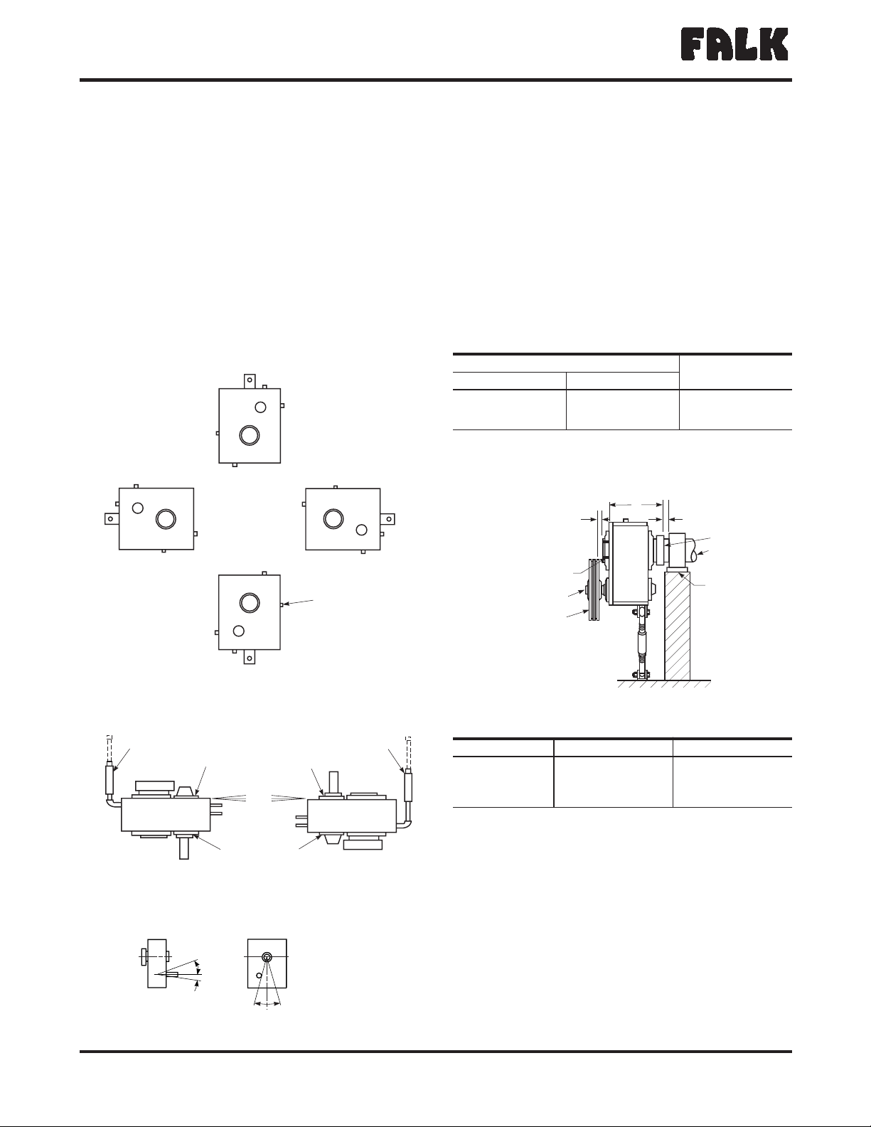
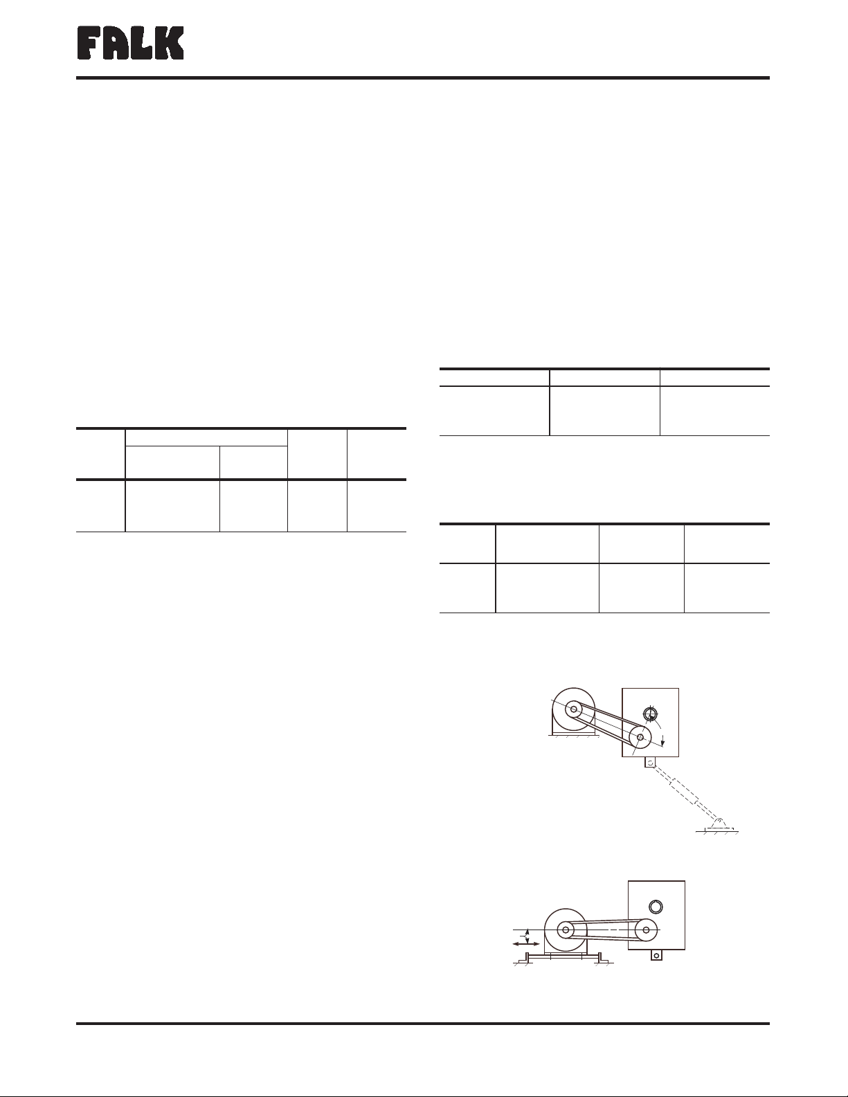
13. JR — When the tie rod turnbuckle is used for belt tension
adjustment, position the motor so that the belt pull will be
about 90° to a line through the drive input shaft and hollow
shaft as shown in Figure 9. For drives where the motor is
moved to adjust belt tension, mount the motor slide base so
that the belt tension adjustment is approximately parallel to
the belt centers. Refer to Appendix D, for instructions relative
to alignment of sheaves and belts.
The Falk Corporation, P.O. Box 492, Zip 53201-0492 378-102
3001 W. Canal St., Zip 53208-4200, Milwaukee, WI USA Telephone : 414-342-3131 August 2004
®
a good name in industry
Quadrive Shaft Mounted Drives •Owners Manual
Sizes 4407/M4407-4608/M4608 (Page 7 of 56)
TABLE 6 — Spanner Wrench Type and
Spanner Nut Tightening Torque
Drive
Size
Adjustable Hook Spanner Wrench Spanner Nut
Tightening
Torque
lb-in (Nm)
Nut Rotation
from Seated
Condition
Armstrong Tools Williams
4407 34-313 6 1/8"-8 3/4" 474B 4000 (452) 180
4415 34-313 6 1/8"-8 3/4" 474B 4000 (452) 180
4507 73-213 HCT-15-2 H4000 (452) 180
4608 73-213 HCT-15-2 H4000 (452) 180
HThese are chain wrenches where standard spanner wrenches are not
available.
TABLE7—JFandJSCDrives—Foundation
Fastener & Tightening Torque
(Non-Lubricated Fasteners)
Drive Size Fastener Size & Grade Torque lb-in (Nm)
4407 .750-10UNC, Gr. 5 2940 (332)
4415 1.250-7UNC, Gr. 5 12600 (1 424)
4507 1.250-7UNC, Gr. 5 12600 (1 424)
4608 1.500-6UNC, Gr. 5 22100 (2 497)
90°
BELT TENSION ADJUSTED
WITH TORQUE ARM
BELT TENSION ADJUSTED
WITH MOVABLE MOTOR
PARALLEL
Figure 9
TABLE8—Thrust Plate Fastener Data
(Non Lubricated Fasteners)
Drive Size Fastener Size
& Grade HTorque lb-in (Nm)
Minimum Thread
Depth
Inches (mm)
4407 1.000-8UNCx4.00, Gr. 8 9500 (1 073) 2.75 (69,9)
4415 1.250-7UNCx4.00, Gr. 8 19150 (2 164) 2.75 (69,9)
4507 1.250-7UNCx4.00, Gr. 8 19150 (2 164) 2.75 (69,9)
4608 1.250-7UNCx4.00, Gr. 8 19150 (2 164) 2.75 (69,9)
HFastener lengths given are for applications using tapered (JSC type driven
shafts. Other lengths may be needed for applications using tapered bushings.

Lubrication
CAUTION: Drives shipped without oil.
14. JR, JF & JSC — Refer to Appendix A for selection of
lubricant. Refer to Table 9 for approximate oil capacity of
drives.
15. JR, JF & JSC — HORIZONTAL MOUNTING
Remove air vent and oil level plug (Refer to Step 1). Fill the
drive until oil shows in the oil level hole. Coat the air vent
and plug threads with #3 Permatex or equivalent thread
sealant before replacing.
JRV, JFV & JSCV — (VERTICAL MOUNTING) - Refer to
Figure 1, Step 1.
Input Shaft DOWN — Remove the fill plug and fill
with oil to level marked on the dipstick.
Input Shaft UP — Remove the oil level and fill plugs
and fill until oil shows in the oil level hole.
Coat the plug threads with #3 Permatex or equivalent
thread sealant before replacing.
If stand pipe is used as oil fill, the intermediate cover plug
must be removed to eliminate entrapped air.
16. JR, JF & JSC — Where applicable, pump grease into the
input seal cover, Figure 10, until the grease appears at the
shaft. Wipe off excess grease from the shaft. DO NOT use
grease where it could contaminate the product e.g. foods,
drugs etc.
Start Up
17. JR, JF & JSC — Before operating the drive, check any fasteners,
pipe plugs, air vent, etc. which may have been loosened in the
course of Outfitting, Installing and Lubricating the drive, to be
sure that they have been properly retightened. Check correct
rotation of motor & backstop and be sure drive is properly
lubricated. After one week of operation repeat check of all
external fasteners and pipe plugs.
18. After one month of operation:
a) Operate the drive until the sump oil reaches normal
operating temperature. Shut the drive down and
drain immediately.
b) Immediately flush the drive with an oil of the same type
and viscosity grade as the original charge (warmed to
approximately 100°F in cold weather). Rapidly pour or
pump a charge equal to 25-100% of the initial fill thru
the drive, or until clean oil flows thru the drain.
c) Close the drain and refill the drive to the correct level
with new or reclaimed oil of the correct type and
viscosity. If determined to be in good condition by the
supplier, drain oil may be reused if it is filtered thru a
100 micron or finer filter.
The Falk Corporation, P.O. Box 492, Zip 53201-0492378-102
3001 W. Canal St., Zip 53208-4200, Milwaukee, WI USA Telephone: 414-342-3131August 2004
®
a good name in industry
Owners Manual •Quadrive Shaft Mounted Drives
(Page 8 of 56) Sizes 4407/M4407-4608/M4608
Figure 10
TABLE9—Approximate Oil Capacity –
Gallons (Liters) H
Drive Size JR, JF & JSC JRV & JFV
4407 4.3 (16,3) 6.3 (23,8)
4415 7.0 (26,5) 9.5 (36,0)
4507 10.3 (39,0) 13.3 (50,3)
4608 25.0 (94,6) 31.3 (118)
HQuantities are approximate. Always fill drive to specified level.

Section II
Drive Service & Repair
Preventive Maintenance
PERIODICALLY — Carefully check the oil level of the drive
when it is stopped and at ambient temperature, add oil if
needed. If the oil level is above the specified level, have the
oil analyzed for water content. Moisture in the oil may
indicate seal leakage or condensation. If so, correct the
defect immediately and change the oil. DO NOT overfill or
oil leakage may result. On vertical shaft drives, remove fill
plug before filling or checking oil level. If a drive is
equipped with a fan, periodically clean accumulated foreign
matter from the fan and fan guard to allow adequate air
flow.
GREASE PURGED SEALS — Periodically (at least every six
months), depending upon the frequency and degree of
contamination, purge contaminated grease by pumping fresh
bearing grease through the seal cage until it flows out along
the shaft. Wipe off the purged grease.
Oil Changes
PETROLEUM LUBRICANTS — For normal operating
conditions, change oil every six months or 2500 hours,
whichever occurs first. If the drive is operated in an area where
temperatures vary with the season, change the oil viscosity to
suit the temperature. Where applicable, grease seals when
changing oil. Refer to Appendix A.
SYNTHETIC LUBRICANTS — Synthetic lube change intervals
can be extended to 8000-10,000 hours based on operating
temperatures and lubricant contamination. Laboratory analysis
is recommended for optimum lubricant life and drive
performance. Change lube with ambient temperature change,
if required. Refer to Appendix A.
Stored & Inactive Drives
NEW DRIVES WHICH HAVE NOT BEEN OPERATED — Each
drive is spin tested with a rust preventive oil that will protect
internal parts against rust for a period of 4 months in an
outdoor shelter or 12 months in a dry building after shipment
from Falk.
If a drive is to be stored or inactive beyond the above periods,
spray all internal parts with a rust preventive oil that is soluble
in lubricating oil or add 1 ounce (0,030 liters) of “Motorstor” H
vapor phase rust inhibitor oil. Seal air vent immediately with
pressure sensitive tape.
Before operating drives which have been stored or inactive,
remove tape and fill to the proper level with oil meeting
specifications given in the Lubrication Recommendation found
in Appendix A.
HProduct of the Daubert Chemical Company, Chicago, Illinois.
(Formerly known as “Nucel Oil.”)
SHUTDOWN OF NEW OR EXISTING DRIVES WHICH
HAVE BEEN OPERATED — If a drive is to be stored or inactive
for more than 2 months after a period of operation, add 1
ounce (0,030 liters) of “Motorstor” Hto the oil sump and
immediately seal the air vent with pressure sensitive tape. It is
not necessary to drain the oil prior to storage if oil is still
serviceable and not contaminated.
Before operating drive, remove tape and check oil level.
PERIODICALLY INSPECT STORED OR INACTIVE DRIVES AND
SPRAY OR ADD RUST INHIBITOR EVERY SIX MONTHS, OR
MORE OFTEN IF NECESSARY. INDOOR DRY STORAGE IS
RECOMMENDED.
Drives Ordered for Extended Storage can be treated at Falk
with a special preservative and sealed to rust-proof parts for
periods longer than those stated above, if specified on the
order.
Repair & Replacement
WARNING: Consult applicable local and national safety
codes for proper guarding of rotating members.
Lock out power source and remove all external loads from
drive before servicing drive or accessories.
NOTE: Only the seals on the input side of the drive can be
replaced without removing the drive from the driven equipment
(Steps 5 thru 8). All other repairs require removal of the drive
from the driven equipment (Steps 1 thru 4).
Removal
See note above if only seal replacement is to be attempted.
1. JR, JF & JSC — Drain the lubricant at this time. Remove
safety guards and belts (motor and motor mount, optional).
Remove backstop (if so equipped) when:
Ratio J05 where rotation arrow indicates Clockwise H.S.
shaft rotation.
Ratio J09, J14, & J25, where rotation arrow indicates
Counter-Clockwise H.S. shaft rotation.
Refer to Section II, Step 10, for backstop removal
instructions.
WARNING: Drive must be supported during removal process.
Use a sling around the motor mount or as recommended in
Section I, Step 6. Take up the slack in the sling before
proceeding.
The Falk Corporation, P.O. Box 492, Zip 53201-0492 378-102
3001 W. Canal St., Zip 53208-4200, Milwaukee, WI USA Telephone : 414-342-3131 August 2004
®
a good name in industry
Quadrive Shaft Mounted Drives •Owners Manual
Sizes 4407/M4407-4608/M4608 (Page 9 of 56)

2. JR — Refer to Appendix C, for instructions for using the TA
torque assist removal tool.
ALTERNATE METHOD — Loosen the setscrew on the
bushing nut which is located at the output end of the
hollow shaft. Use a spanner, pipe or chain wrench to
loosen the bushing nut (Section I, Table 6). Initially, the
nut will freely rotate counter clockwise approximately
180° as the nut moves from the locked position to the
removal position. At this point anticipate resistance which
indicates unseating of the bushing. Continue to turn the
nut until it is free from the hollow shaft. Prepare drive for
lifting (Figure 7, Page 6) by disconnecting the tie rod at
the drive end. Slide the drive from the bushing. The
bushing can be left in place or removed, as required. If
bushing will not slide off of the shaft, insert a small prybar
into the split of the bushing and pry the split open slightly
to loosen the bushing and remove from the shaft. For
replacement of seals only proceed to Step 5, otherwise
Step 9.
3. JF — Remove the output shaft cover, Ref. #14 (Figure 14,
Page 14), from the input end of the hollow shaft. Remove
the bolts which fasten the mounting flange to the driven
equipment.
Remove the fastener, retaining ring, and thrust plate from the
hollow shaft. Refer to Table 10 and select a backing bolt
and flat washer and install them into the drive shaft as
illustrated in Figure 11. The bolt head provides a working
surface for the removal bolt. Reinsert the thrust plate and
retaining ring into the hollow shaft and select a removal bolt
from Table 10. Thread the removal bolt into the thrust plate
until it contacts the backing bolt head. Torque the removal
bolt to the value shown in Table 10. (If the thrust plate
rotates in the shaft, align the slot in the plate with the hollow
shaft keyway and insert a screw driver or piece of key stock
to prevent rotation of the plate). After torquing the bolt, as
instructed, strike the bolt, sharply with a hammer and
retorque the bolt if separation of the drive from the shaft did
not occur. Repeat this procedure, retorquing the bolt after
each blow, until separation occurs.
CAUTION: Failure to follow this procedure may result in the
destruction the threads in the thrust plate. (If the retaining
ring becomes damaged, refer to Appendix H, for
replacement information).
Proceed as follows:
JF to Step 5 for replacement of Quadrive seals only OR Step
9 for drive disassembly procedure.
4. JSC (4407 only) — Prepare drive for lifting as shown in
Figure 7, Page 6. Remove drive from driven equipment
trough end by removing the trough end mounting screws
from seal housing. Remove coupling bolts from drive
shaft and slide drive with drive shaft away from the driven
equipment.
To remove drive shaft from the drive, remove the output
shaft cover, Ref. #14 (Figure 14, Page 14), from the input
end of the hollow shaft and then refer to Step 3 above. The
procedure to separate the JSC drive from the shaft is the
same as for separation of a JF drive from driven equipment
shaft.
After separation of the drive and shaft has been achieved,
determine the type of seal equipped in the seal housing. If it
is a waste packing seal, remove the waste packing material
and then remove the loosened drive shaft from the seal
housing side of the drive. If equipped with a lip seal, first
remove the lip seal following the removal instructions from
Step 5 below. After seal is removed from seal housing,
remove the loosened drive shaft from the seal housing side
of the drive.
CAUTION: The seal housing acts as the bearing cage,
therefore, NO NOT remove from the drive unless complete
drive disassembly is anticipated. Removal of the seal housing
will require readjustment of the L.S. bearings (Section III,
Page 21).
The Falk Corporation, P.O. Box 492, Zip 53201-0492378-102
3001 W. Canal St., Zip 53208-4200, Milwaukee, WI USA Telephone: 414-342-3131August 2004
®
a good name in industry
Owners Manual •Quadrive Shaft Mounted Drives
(Page 10 of 56) Sizes 4407/M4407-4608/M4608
TABLE 10 — Removal & Backing Bolt Size and
Length – Inches
Drive
Size
Removal Bolt
Size & Minimum
Length
Maximum
Tightening Torque –
lb-in (Nm)
Backing Bolt
Size & Maximum
Length
4407 1.125-7UNC x 3.00 8900 (1 006) 1.000-8UNC x 2.50
4415 1.500-6UNC x 3.75 22100 (2 497) 1.250-7UNC x 2.75
4507 1.500-6UNC x 3.75 22100 (2 497) 1.250-7UNC x 2.75
4608 1.500-6UNC x 3.75 22100 (2 497) 1.250-7UNC x 2.75
RETAINING
RING
THRUST
PLATE
REMOVAL
BOLT
BACKING BOLT TAPPED HOLE
IN DRIVE SHAFT
DRIVE SHAFT
FLAT WASHER
HOLLOW
SHAFT
Figure 11

DRIVE DISASSEMBLY — (Refer To Parts Drawing Figure 19)
Prior to initiating any disassembly or repair, clean accumulated
dirt and grime from the surface of the drive housing. Clean the
exposed portion of the input and output shafts with a solvent
and a non-abrasive cloth. If the seals only are being replaced
proceed to Step 5. If the drive will be disassembled for
inspection or repair, skip to Step 9.
CAUTION: Do not damage shaft; new seals will leak if seal
contacting surface is marred. Do not use abrasive material on
shaft seal contacting surface.
5. SEAL REMOVAL — (When drive is to be disassembled, skip
to Step 9, Page 12.) Replacement is recommended. When
removing seals, maintain shafts in a horizontal plane to
prevent any foreign matter from falling into the drive
bearings. Drain oil from drive. Refer to Figures 12, 13, 14 &
15.
Input Seals — Seals can be replaced without removing the
drive from the driven shaft. However, the seal cage must be
removed to access the seal.
Sizes 4407-4507 — Remove seal cage, Ref. #21,
and save shim-gaskets, Ref. #31, for reference when
reassembling. Drive out old seal from seal cage.
Scrape old Permatex from bore exercising caution not
to score the bore.
Size 4608 — Remove seal cage, Ref. #38, and save
shim-gaskets, Ref. #39, for reference when
reassembling. For H.S. seal removal on drives having
a cooling fan or backstop, first remove the accessory
and then remove the seal cage, Ref. #63 or #66.
Save shim-gaskets for reference.
All Sizes — Drive out old seal from seal cage. Scrape
old Permatex from the bore exercising caution not to
score the bore.
Output Seals (Figures 14 & 15) — Drive removal from
driven equipment may be necessary. Refer to removal
instructions, Section II, Page 9.
After dismounting drive from driven equipment, remove the
output shaft cover, Ref. #14, on Sizes 4407-4507. NO
NOT remove seal cages, Ref. #11 or #12, Sizes
4407-4507, and Ref. #22 or #27, Size 4608. Removal of
these cages will require readjustment of the bearings
(Section III, Page 21).
Refer to Figures 12, 13, 14 & 15 and remove seals as
follows:
a) Clean shaft extension with solvent and remove all sharp
edges. Use a sharp center punch to lightly punch the seal case
as a guide for the drill. NOTE: DO NOT drive seal into the
bore too deep. Seals are not axially retained and disassembly
of the drive may be required if the seal is driven too deep.
b) Wrap several turns of tape around a .125" (3mm) diameter
drill approximately .250" (6 mm) from the drill point to
prevent the drill from entering too deeply into the housing
and damaging the bearing. Grease or magnetize the drill to
help retain the chips. Drill two .125” (3 mm) diameter holes
in the seal case 180° apart. Control the angle of the drill as
illustrated in Figure 13 to prevent damage to the shaft.
c) Insert two #10-.750" sheet metal screws into the seal
case leaving .500" of the screw protruding above the seal
face. DO NOT drive the screw more than .250" (6 mm)
beyond seal face or bearing damage may occur. Use a
claw type pry bar under the screw head as shown in
Figure 13 and lift the seal out. Remove all chips. Use a
magnet to remove the chips that fall into the bore. Flush
the drive to remove chips from the bearing. Remove
Permatex from the housing bore.
The Falk Corporation, P.O. Box 492, Zip 53201-0492 378-102
3001 W. Canal St., Zip 53208-4200, Milwaukee, WI USA Telephone : 414-342-3131 August 2004
®
a good name in industry
Quadrive Shaft Mounted Drives •Owners Manual
Sizes 4407/M4407-4608/M4608 (Page 11 of 56)
REF. #14
HOLLOW SHAFT
COVER
(4407-4507 ONLY)
REF. #31
REF. #23 REF. #21 REF. #39
INPUT SIDE
HIGH SPEED SHAFT
Figure 12
Figure 13
RIGHT WAY
WRONG WAY

6. SEAL SURFACE CONDITION — Carefully inspect polished
surface of shaft where the seal makes contact. If the seal
surface shows any sign of a nick, scratch, spiral swirl or
groove, the shaft should be replaced or refurbished to
prevent leakage of the lubricant. (In many instances the seal
surface can be restored by use of a thin wall wear sleeve.
Check with your local seal supplier and follow the
manufacturer’s instructions for installing the wear sleeve).
7. SEAL INSTALLATION
CAUTION: Protect seal lips from sharp edges of the keyway
by wrapping thin strong paper around the shaft and coating
the paper and seal lips with grease before sliding the seal on
or off the shaft. Do not expand the seal lips more than .030"
(0,75 mm) diameter.
a) Install seals into seal cages where cages must be removed
from drive:
4407-4507; All types, H.S. seals.
4407 JF & JSC; L.S. seals (output side).
4608; All types, H.S. & L.S. seals.
Coat O.D. of seal with Permatex #3 or equivalent
sealant. Position seal squarely in seal cage with spring
loaded lip toward drive. Drive or press seal into cage
using a flat faced tool until seated. If drive was not
disassembled, select new shims(Ref. #31 or 24, Sizes
4407-4507; Ref. #39 or 23, Size 4608) from shim kit,
Ref. #100, to match those removed in Step 5.
If drive was disassembled, install the complete seal cage
shim pack (Ref. #31 or 24, 39 or 23). Carefully slip seal
cage with seal over the shaft. Replace fasteners and cross
tighten to torques listed in Table 14, Section III. Reset axial
float per instructions in Section III, Page 21.
b) Install seals into seal bores where seal cages may remain
attached to housing:
4407 JF & JSC; L.S. seals (input side).
4407-4507JR; L.S. seals (input & output sides).
4415-4507JF; L.S. seals (input & output sides).
Coat O.D. of seal with Permatex #3 or equivalent
sealant. Carefully slip seal over shaft and position
squarely in seal bore with spring loaded lip toward drive.
Use a cylindrical square faced tool to drive or press seal
into bore until outer seal wall is seated 0.14" (3,5 mm)
inside the seal bore outer wall.
CAUTION: DO NOT seat seal against bearing; a
shoulder is NOT provided for stopping the seal. Measure
seal axial runout with a dial indicator mounted on the
shaft. If the seal axial runout is more then 0.010" (0,25
mm), tap high side of seal with installation tool until seal
axial runout is 0.010" (0,25 mm) or less.
8. DRIVE REPAIR IS COMPLETE — Review instructions in
Section I for reassembly of drive onto driven shaft.
Drive Disassembly — Continued
9. When seals, Ref. #21 & 23 (4407-4507); Ref. #21, 37 &
64 (4608), are to be reused (Replacement is
recommended), wrap the input shaft keyway and output
shaft threads with masking tape or light weight kraft paper to
protect seal lips during disassembly. Cover wrapping with a
light coat of grease.
10. Remove backstop parts if so equipped. For Sizes 4407,
4415J14 & 4507J14 remove cover Ref. #19, backstop Ref.
#5A and appropriate spacers & retaining rings from
backstop cage. Re-install cover and finger tighten fasteners.
For Sizes 4415J25 & 4507J25, remove entire backstop
cage. Disassemble retaining rings and remove backstop.
Re-install cage and cover without the backstop and finger
tighten fasteners. (For all drives, note direction of rotation of
input shaft for proper reassembly.)
11. Lay drive on bench with input shaft up. Remove housing
cover fasteners, Ref. #33, Sizes 4407-4507; Ref. #13, Size
4608. Screw eyebolts into tapped holes (5/8 - 11UNC,
Sizes 4407-4507; 3/4 - 10UNC, Size 4608) diagonally
opposite in cover plate. Eyebolts can be used to jack the
cover off the dowels. Attach hoist cables and lift cover plate
off housing base.
12. Remove the shaft assemblies (J05 = 3A & 4A, J14 or J25 =
1A, 2A & 4A) from output housing, Ref. #10, using eye bolts
for the high speed shaft and low speed pinion assemblies (3/8
- 16UNC Sizes 3407 - 3507; ½ - 13UNC Size 4608). All low
speed shaft assemblies can be lifted by slinging through holes
in the gear web.
13. Turn housing on either narrow side. If tapered roller
bearings are being replaced, remove end covers and seal
cage from output side of drive and drive bearing cups
through the bores. Remove bearing cups from the housing
cover in the same manner.
14. Drive seals out from base and cover bores and seal
cages if replacement is indicated. Remove gasket
material, seal compound and any accumulated foreign
matter from seal joints, bores and adjacent sealing
surfaces. Use a solvent to clean out the housing covers
and shaft assemblies.
15. If drive is equipped with an internal backstop, check
the shaft surface and the backstop sprags (inside
diameter) for signs of wear. If either component shows
evidence of wear, both should be replaced (Assemblies
Ref. #1A and 5A). Also refer to Step 6 for inspection of
seal surfaces.
The Falk Corporation, P.O. Box 492, Zip 53201-0492378-102
3001 W. Canal St., Zip 53208-4200, Milwaukee, WI USA Telephone: 414-342-3131August 2004
®
a good name in industry
Owners Manual •Quadrive Shaft Mounted Drives
(Page 12 of 56) Sizes 4407/M4407-4608/M4608

16. Inspect gear teeth for wear or indications of fatigue, e.g.
hairline cracks at the root of the tooth. If one element has
undergone severe wear or broken teeth, replace the mating
element also.
17. Clean and inspect bearings for wear. Lubricate with light
oil before spinning to avoid scoring of working surfaces.
Remove any worn bearings with a wheel puller. If tapered
roller bearings are being replaced, drive the bearing
cups out of the housing base and cover, Ref. #10. DO
NOT use new cone assemblies with worn (old) cups.
18. If gears are to be replaced, use a wheel puller or press to
remove gears Ref. #1A4 or 4A4 from their shaft. Exercise
caution to avoid scoring shaft seal diameter with the keyway
in the gear.
19. Inspect all fasteners for damage or wear and replace with
fasteners of equal grade. Grade 5 fasteners
have three (3) radial lines on the head.
Fasteners are available in kit form, Ref. #80.
20. If the shaft assemblies can be reused intact
(no new parts required), refer to Section III,
Steps 6 thru 8, for reassembly procedure. Replace all
shim-gaskets with new parts, Kit Ref. #100. Use the same
thicknesses as removed during disassembly.
Identifying & Ordering Parts
1. Refer to the parts diagram, Figures 14 or 15, and make a
list of the parts required by part reference number. For
example, Ref. #21, 23, 100, 1A, 2A1, and 2A2. When a
gasket joint is separated, always replace with new
shim-gaskets. Order Ref. #100 shim-gasket kit.
2. Now refer to the parts list, Table 11, and determine the part
description and Falk part number using the part reference
number (Step 1) and the drive identification (e.g. 4407J25)
in the column headers of the parts list.
3. Use the part description and Falk part number to order the
required parts. In the examples of preceding Steps 1 and 2,
Ref. #21, 23, 100, 1A, 2A1 and 2A2 for a 4407J25, parts
would be ordered as follows:
Ref. #21 — Seal cage ············4723117
Ref. #23 — Seal···············0912913
Ref. #100 — Shim-gasket kit ·········4723120
Ref. #1A — Shaft assembly with gear ·····4723133
Ref. #2A1 — Bearing ············0921780
Ref. #2A2 — Bearing ············0921780
4. Tables 12 and 13 converts Falk part numbers to bearing and
seal manufacturer’s part numbers. Tooth combinations are
listed in Appendix H.
5. Place your order with your local Falk Distributor. If you need
to locate a distributor, phone (414) 342-3131.
Recommended Spare Parts
1. For non-critical drive applications a complete set of
bearings, seals and shim-gaskets is recommended. If stored
in their original packaging in a dry, cool location, these
parts have a minimum shelf life of 5 years.
2. For critical drive applications (where an outage would create
a major production loss), a complete drive is recommended.
The Falk Corporation, P.O. Box 492, Zip 53201-0492 378-102
3001 W. Canal St., Zip 53208-4200, Milwaukee, WI USA Telephone : 414-342-3131 August 2004
®
a good name in industry
Quadrive Shaft Mounted Drives •Owners Manual
Sizes 4407/M4407-4608/M4608 (Page 13 of 56)
LOW SPEED
GEAR
LOW SPEED
PINION ASSEMBLY
HIGH SPEED
SHAFT ASSEMBLY
OPTIONAL BACKS
T
ASSEMBLY
HIGH SPEED
GEAR
HOLLOW SHAFT
HOUSING BASE
AIR VENT
COVER PLATE
HOLLOW
SHAFT COVER

The Falk Corporation, P.O. Box 492, Zip 53201-0492378-102
3001 W. Canal St., Zip 53208-4200, Milwaukee, WI USA Telephone: 414-342-3131August 2004
®
a good name in industry
Owners Manual •Quadrive Shaft Mounted Drives
(Page 14 of 56) Sizes 4407/M4407-4608/M4608
Figure 14 — Sizes 4407 thru 4507
34
37
37
35
15 25
22 11
24
4415 & 4507
ILLUSTRATED
41
42
12
38
10
19
INTERCHANGEABLE
30
29
20
18 28
17
27
4A2 4A5
4A1
4A4
2A2 2A4
2A3
2A1
1A4
1A2
1A1
1A3
1A5
3A2
3A1
3A4
3A3
TYPES
J14 & J25
TYPE
JO5
4A3
4A2 4A5
4A1
4A4
4A6
4A3
4A
ASSY.
2A ASSY.
1A ASSY.
10
4A ASSY.
3A ASSY.
24
11
22
16
34
26
33
31 23
21
39
36
33
6A ASSY.
6A1 6A2
6A3
5A ASSY.
29 5A4
5A1
5A2
40
32

The Falk Corporation, P.O. Box 492, Zip 53201-0492 378-102
3001 W. Canal St., Zip 53208-4200, Milwaukee, WI USA Telephone : 414-342-3131 August 2004
®
a good name in industry
Quadrive Shaft Mounted Drives •Owners Manual
Sizes 4407/M4407-4608/M4608 (Page 15 of 56)
Figure 15 — Size 4608
40
6A1 ASSEMBLY
38
39
11 10
12
31
37
21 30
29
24
22
23
13
TYPE
J25 4A ASSEMBLY
2A
ASSEMBLY
1A ASSEMBLY
10
17
27 22INTERCHANGEABLE
23
24
21
39
29
30
31
40 6A1 ASSEMBLY
65
64
39
40
64
40
5A ASSEMBLY
66
39
67
106A
18
63
6A2
6A1
BACK FAN ASSEMBLYFRONT FAN ASSEMBLY
6A1 6A4
6A10
6A36A3 6A4
6A11
1A4
1A2
1A5 1A1 1A3
2A4
2A3
2A1 2A5 2A2
4A6
4A1
4A7
4A3 4A5 4A4
4A2

The Falk Corporation, P.O. Box 492, Zip 53201-0492378-102
3001 W. Canal St., Zip 53208-4200, Milwaukee, WI USA Telephone: 414-342-3131August 2004
®
a good name in industry
Owners Manual •Quadrive Shaft Mounted Drives
(Page 16 of 56) Sizes 4407/M4407-4608/M4608
TABLE 11 — Parts List Of Falk Part Numbers
Ref.
No. Part Description Drive Size
4407 4415 4507
Housing Components - J05, J14 & J25
11 Seal Cage 0352865 0344480 0344425
12 Flange – Seal Housing 0352889 . . . . . .
12 Mounting Flange . . . 0426963 0426935
14 Shaft Cover 2110604 4723140 4723160
15 Shaft Cover 4723114 4723163 4723163
16 Shaft Cover 4723114 4723142 4723164
17 Shaft Cover - Type J05 4723115 0344426 0344426
18 Shaft Cover - Type J14 & J25 2110747 0344426 0344426
19 Shaft Cover - Type J14 & J25 1219672 0344428 0344428
20 Backstop Cage - Type J14 1231142 0344429 0344429
20 Backstop Cage - Type J25 1231142 0344427 0344427
21 Seal Cage 4723117 4723144 4723165
22 Seal 2912056 0912765 0912742
22 Seal, 4407JF, JSC, Seal Hsg. Side 2912098 . . . . . .
23 Seal 0912913 0912913 0912858
40 Tie Rod Anchor Assembly 0757211 0712831 0712831
41 Air Vent 0914088 0914088 0914088
80 Fastener Kit - Includes Ref. #33 thru 39 & 42 4723119 4723145 4723166
100 Shim-Gasket Kit - Includes Ref. #24 thru 32 4723120 0758580 0758587
Rotating Elements - J05
3A Shaft Assembly - Includes Ref. #3A1 - 3A4 4723121 4723146 4723167
3A1 Bearing 0921855 0921494 0921752
3A2 Bearing 0921863 0921859 0921858
3A3 Pinion & Shaft - Includes Ref. #3A4 4723122 4723147 4723168
4A Shaft Assembly - Includes Ref. #4A1 - 4A5 4723124 4723150 4723170
4A1 Bearing 2905186 0921861 0921755
4A2 Bearing 2905186 0921861 0921755
4A3 Hollow Shaft - Includes Ref. #4A5 4723125 4723149 4723171
4A4 Gear 1231140 1231313 1231353
6A1 Fan 4723126 4723126 4723172
6A3 Guard 4721426 4721426 4723173
6A4 Grill 4723127 4723127 4723174
Rotating Elements - J14
1A Shaft Assembly With 1A4 Gear 4723128 4723151 4723175
1A Shaft Assembly Without 1A4 Gear 4723129 0758575 0758582
1A1 Bearing 0921682 0921529 0921752
1A2 Bearing 2915106 0921860 0921858
1A3 Pinion & Shaft - Includes Ref. #1A5 4723130 4723152 4723179
1A4 Gear 1219666 1220256 1220136
5A Backstop Assembly - Includes Ref. #5A1 - 5A4 4723132 4723153 4723153
Rotating Elements - J25
1A Shaft Assembly With 1A4 Gear 4723133 4723154 4723176
1A Shaft Assembly Without 1A4 Gear 4723134 0758576 4723178
1A1 Bearing 0921349 0921494 0921752
1A2 Bearing 2915107 0921859 0921857
1A3 Pinion & Shaft - Includes Ref. #1A5 4723135 4723155 4723180
1A4 Gear 1219665 1220258 1220138
5A Backstop Assembly - Includes Ref. #5A1 - 5A4 4723132 4723156 4723156
Rotating Elements - J14 & J25
2A Shaft Assembly - Includes Ref. #2A1 - 2A4 4723137 4723157 4723182
2A1 Bearing 0921780 0921556 0921752
2A2 Bearing 0921780 0921556 0921530
2A3 Pinion & Shaft - Includes Ref. #2A4 4723138 4723158 4723183
4A Shaft Assembly - Includes Ref. #4A1 - 4A5 4723124 4723150 4723170
4A1 Bearing 2905186 0921861 0921755
4A2 Bearing 2905186 0921861 0921755
4A3 Hollow Shaft - Includes Ref. #4A5 4723125 4723149 4723171
4A4 Gear 1231140 1231313 1231353
6A1 Fan 4723126 4723126 4723172
6A3 Guard 4721426 4721426 4723173
6A4 Grill 4723127 4723127 4723174
Continued on next page

The Falk Corporation, P.O. Box 492, Zip 53201-0492 378-102
3001 W. Canal St., Zip 53208-4200, Milwaukee, WI USA Telephone : 414-342-3131 August 2004
®
a good name in industry
Quadrive Shaft Mounted Drives •Owners Manual
Sizes 4407/M4407-4608/M4608 (Page 17 of 56)
TABLE 11 — Parts List Of Falk Part Numbers (Continued)
Ref.
No. Part Description Unit Size
4608
Housing Components - J25
17 Air Vent 0720000
21 Seal 0912768
22 Seal Cage 4723185
27 Mounting Flange - Type JF 4723190
30 Shaft Cover 4723192
37 Seal 0912758
38 Seal Cage 4723186
63 Seal Cage 4723187
64 Seal 0912757
65 Shaft Cover 0284960
66 Seal Cage 4723188
67 Yoke 4723194
80 Fastener Kit - Includes Ref. #11,13,18,24,31 & 40 4723195
100 Shim-Gasket Kit Includes Ref. #12, 23, 29 & 39 4723196
106 Tie Rod Anchor Assembly(JR only) 0712831
Rotating Elements - J25
1A Shaft Assembly With 1A4 Gear - Without Fan or Backstop 4723197
1A Shaft Assembly With 1A4 Gear - With Fan or Backstop 4723198
1A Shaft Assembly Without 1A4 Gear - Without Fan or Backstop 4723199
1A Shaft Assembly Without 1A4 Gear - With Fan or Backstop 4723200
1A1 Bearing 0921751
1A2 Bearing 0921752
1A3 Pinion & Shaft - Unit Without Fan or Backstop 4723201
1A3 Pinion & Shaft - Unit With Fan or Backstop 4723203
1A4 Gear 0352892
2A Shaft Assembly - Includes Ref. #2A1 - 2A5 4723205
2A1 Bearing 0921352
2A2 Bearing 0921352
2A3 Pinion & Shaft - Includes Ref. #2A5 4723207
2A4 Spacer 1231228
4A Shaft Assembly - Includes Ref. #4A1 - 4A6 4723209
4A1 Bearing 2905910
4A2 Bearing 2905910
4A3 Hollow Shaft 4723210
4A4 Gear 0352893
4A5 Spacer 1231229
5A Backstop 0755442
6A1 Fan 4723214
6A2 Bushing 4723215
6A3 Guard 4723173
6A4 Grill 4723216
6A10 Shaft Guard 4723217
6A11 Deflector 0294866

The Falk Corporation, P.O. Box 492, Zip 53201-0492378-102
3001 W. Canal St., Zip 53208-4200, Milwaukee, WI USA Telephone: 414-342-3131August 2004
®
a good name in industry
Owners Manual •Quadrive Shaft Mounted Drives
(Page 18 of 56) Sizes 4407/M4407-4608/M4608
TABLE 12 — Bearing Cross Reference
Numbers
Falk Part Number Manufacturers Number
Tapered Roller Bearings H
921349 HM212046/HM212011
921352 6580/6535
921494 H715336/H715311
921529 H715345/H715311
921530 H414249/H414210
921556 H715332/H715311
921682 HM212049/HM212011
921751 JH217249/JH217210
921752 JH415647/JH415610
921755 JM736149/JM736110
921780 HM212044/HM212011
921855 5584/5535
921857 65212/65500B
921858 65237/65500B
921859 65200/65500B
921860 65225/65500B
921861 67782/67720
921863 5565/5535
2905186 LM330448/LM330410
2905910 LM742749/LM742710
2912058 HM807040/HM807015B
2912059 HM807035/HM807015B
HFalk suppliers of Tapered Roller Bearing are: Timken, Bower and Tyson.
TABLE 13 — Seal Cross Reference Numbers
Falk Part Number Manufacturers Number †
Chicago Rawhide National
912742 70080 477436
912757 . . . 417316
912758 29906 . . .
912765 64993 . . .
912768 85014 . . .
912858 29317 416654
912913 24898 471271
2912056 60004 . . .
†Subject to substitution of equivalent seals without notice.

Section III
Drive Reassembly
Refer To Parts Drawing Figures 14 & 15.
1. GENERAL
a) Clean all parts to be reassembled and coat all taper roller
bearing cups and pinion teeth with oil. DO NOT
lubricate gear teeth prior to assembly on shaft.
b) Heat all tapered roller bearing cones in an oven to
275°F(135°C).
CAUTION: Do not apply flame directly to bearings or rest
bearings directly on a heated surface.
c) Slide or press all bearing cones tight against the shoulder
or spacer.
CAUTION: Do not apply force to the bearing outer race.
Apply force against the inner race only.
2. ASSEMBLY OF ROLLER BEARING CUPS — Where
bearings will be reused and where bearing cups were not
removed from the housing, skip to Step 3. It is
recommended that bearings be replaced when ever drive is
disassembled after being in service.
Install bearing cups only in housing base at this time. Coat
bearing cups and housing bores with an SAE 20(or heavier)
oil and drive or press cup squarely into the housing bores
until positioned as shown in Figure 16 and 17. Use a flat
plate and a brass bar to avoid damaging the bearing cups.
NOTE, that the exact positioning of the bearings in the
bores will be achieved during the bearing adjustment
procedure in Step 6.
CAUTION: Take care not to allow cups to cock during their
installation as this could result in permanent damage to
housing.
If cups become cocked in the bores, tap the high side lightly to
re-position.
3. ASSEMBLE SEAL CAGES TO HOUSING OUTPUT SIDE
(BASE) AS FOLLOWS:
a) Turn housing on work bench to its side being careful that
the bearing cups do not fall out of the bores. Assemble
low speed seal cage without seal and one .015" (0,38
mm) shim-gasket, Ref. #11 or 12 and 24 for Sizes 4407
- 4507 & Ref. #22 or 27 and 23 for Size 4608. Cross
tighten fasteners, Ref. #34 for Sizes 4407- 4507 & Ref.
#24 for Size 4608, to torque specified in Table 14.
Check to be sure that cages and covers are registered on
the bearing cups to avoid hanging up of the cups.
b) Assemble intermediate end cover and one .015" (0,38 mm)
shim-gasket, Ref. #15 and 25 for Sizes 4407 - 4507 & Ref.
#29 and 30 for Size 4608. Cross tighten fasteners, Ref.
#35 for Sizes 4407- 4507 and Ref. #31 for Size 4608, to
torque specified in Table 14.
c) Assemble high speed pinion shaft cover or seal cage
without seal as follows:
Size 4407 - 4507 without backstop — Shaft cover, one
.015" (0,38 mm) shim-gasket and cross tighten fasteners
to torque specified in Table 14. (Ref. #17, 27 and 37 for
Type J05 & Ref. #18, 28 and 37 for Type J14 & J25).
Size 4407- 4507 with backstop — Backstop cage, shaft
cover, shim-gaskets and finger tighten the fasteners, Ref.
#19, 20, 29, 30 and 38. The backstop will be installed
following assembly of shaft assemblies into drive housing.
Size 4608 without backstop — Shaft cover, one .015"
(0,38 mm) shim-gasket and cross tighten fasteners to
torque specified in Table 14, (Ref. #39, 40 and 65).
The Falk Corporation, P.O. Box 492, Zip 53201-0492 378-102
3001 W. Canal St., Zip 53208-4200, Milwaukee, WI USA Telephone : 414-342-3131 August 2004
®
a good name in industry
Quadrive Shaft Mounted Drives •Owners Manual
Sizes 4407/M4407-4608/M4608 (Page 19 of 52)
TABLE 14 — Fastener Tightening Torques
Fastener Size — Inches .375-16 .500-13 .750-10 .750-10 .875-9
Tightening Torque
lb-in (Nm)H
330
(37)
825
(93)
3960
(447)
Size 4608:
2940 (332) 6400
(723)
All Others
3960 (447)
HTorques are for non-lubricated fasteners.
Figure 16
4A2
LOW SPEED SHAFT
BEARING BORE
1A2
HIGH SPEED SHAFT
BEARING BORE
2A2
INTERMEDIATE
PINION BEARING BORE
Figure 17

Size 4608 with fan on back side — Seal cage without
seal, one .015" (0,38 mm) shim-gasket and cross tighten
fasteners to torques specified in Table 14, (Ref. #39, 40
and 63). Seal will be added later.
Size 4608 with external backstop — Seal cage without
seal, one .015" (0,38 mm) shim-gasket and cross tighten
fasteners to torque specified in Table 14, (Ref. #39, 40
and 66). Seal will be added later.
4. SHAFT ASSEMBLIES — Where bearings and gears were
not removed from the shafts, skip to Step 5. If bearings
and gears were removed from the shafts, reassemble
parts on the shaft per Figures 18 thru 21 as follows:
a) To assemble gear (Ref. #1A4 or 4A4), heat gear in an oven
to 275°F(135°C) and press onto the shaft & firmly against
the shoulder. For Size 4608, be sure to place spacers in the
proper location on shaft assemblies 2A and 4A, before
pressing on the bearings.
b) To assemble bearings, heat bearing cone in an oven to a
maximum of 275°F(135°C), then slide or press them tight
against the shaft shoulder or spacer.
CAUTION: Allow assembly to cool. Apply a coat of oil to
the cooled bearings and gear teeth to lubricate & avoid
scoring of the working surfaces.
5. DRIVE ASSEMBLY — Turn drive housing base on work
bench to allow the shaft assemblies to be lowered into the
housing. Block up the housing so that when low speed shaft
assembly, 4A, is in place, the threaded end of the shaft will
clear the bench surface. Before assembly, inspect housing
and all shaft assemblies to see that all foreign matter has
been removed.
Use eye bolts to assist in lowering high speed shaft and low
speed pinion assemblies (Ref. #1A, 2A and 3A) into the
housing base. Lift the low speed shaft assembly (Ref. #4A) by
slinging thru holes in the gear web. Assemble as follows:
a) SINGLE REDUCTION — Lower high speed shaft
assembly, Ref. #3A, Figure 19, into housing and tip away
from other housing bores. While lowering the low speed
shaft assembly, Ref. #4A, Figure 21, into housing tip high
speed shaft into the gear mesh of the low speed gear as
the shaft nears final position.
b) DOUBLE REDUCTION — Lower high speed shaft
assembly, Ref. #1A, Figure 18, into housing and tip away
from other bores. Simultaneously lower the intermediate
shaft assembly, Ref. #2A, Figure 20, and the low speed
shaft assembly, Ref. #4A, Figure 21, into the housing. As
shafts approach their final position, tip the high speed
shaft pinion into the high speed gear mesh, Ref. #1A4.
The Falk Corporation, P.O. Box 492, Zip 53201-0492378-102
3001 W. Canal St., Zip 53208-4200, Milwaukee, WI USA Telephone: 414-342-3131August 2004
®
a good name in industry
Owners Manual •Quadrive Shaft Mounted Drives
(Page 20 of 52) Sizes 4407/M4407-4608/M4608
1A1
BEARING
SHAFT
EXTENSION
1A3
PINION/SHAFT
BACKSTOP
END
(SIZES 4407 & 4415) 1A2
BEARING
SHAFT
EXTENSION
SIZES 4507 & 4608
(BACKSTOP)
Figure 18 — 1A Shaft Assembly
3A1
BEARING
3A3
PINION/SHAFT
3A2
BEARING
SHAFT
EXTENSION
Figure 19 — 3A Shaft Assembly
1A4
GEAR
2A3
PINION/SHAFT
2A1
BEARING
2A2
BEARING
2A4
KEY
Figure 20 — 2A Shaft Assembly
4A6
SPACER
(4608 ONLY)
4A3
HOLLOW
SHAFT
4A2
BEARING
4A4
GEAR
4A1
BEARING
4A5
KEY
Figure 21 — 4A Shaft Assembly
This manual suits for next models
2
Table of contents
Other FALK Industrial Equipment manuals
Popular Industrial Equipment manuals by other brands

TOX
TOX FinePress PFS Original operating instructions

IMI PNEUMATEX
IMI PNEUMATEX Transfero TVI Connect Install

Swegon
Swegon CASA W03CMB Installation instruction

Inciner8
Inciner8 i8-75a Installation & operation manual

Ashcroft
Ashcroft V02 Installation and maintenance instructions

AGI BATCO
AGI BATCO 1800 Series Assembly manual