Famco Danfoss Maneurop MT User manual

Maneurop® reciprocating
compressors MT / MTZ
50 - 60 Hz - R22 - R417A - R407A/C/F - R134a - R404A / R507
Application guidelines
http://danfoss.us.com/


Application guidelines
4FRCC.PC.004.A9.22
Contents
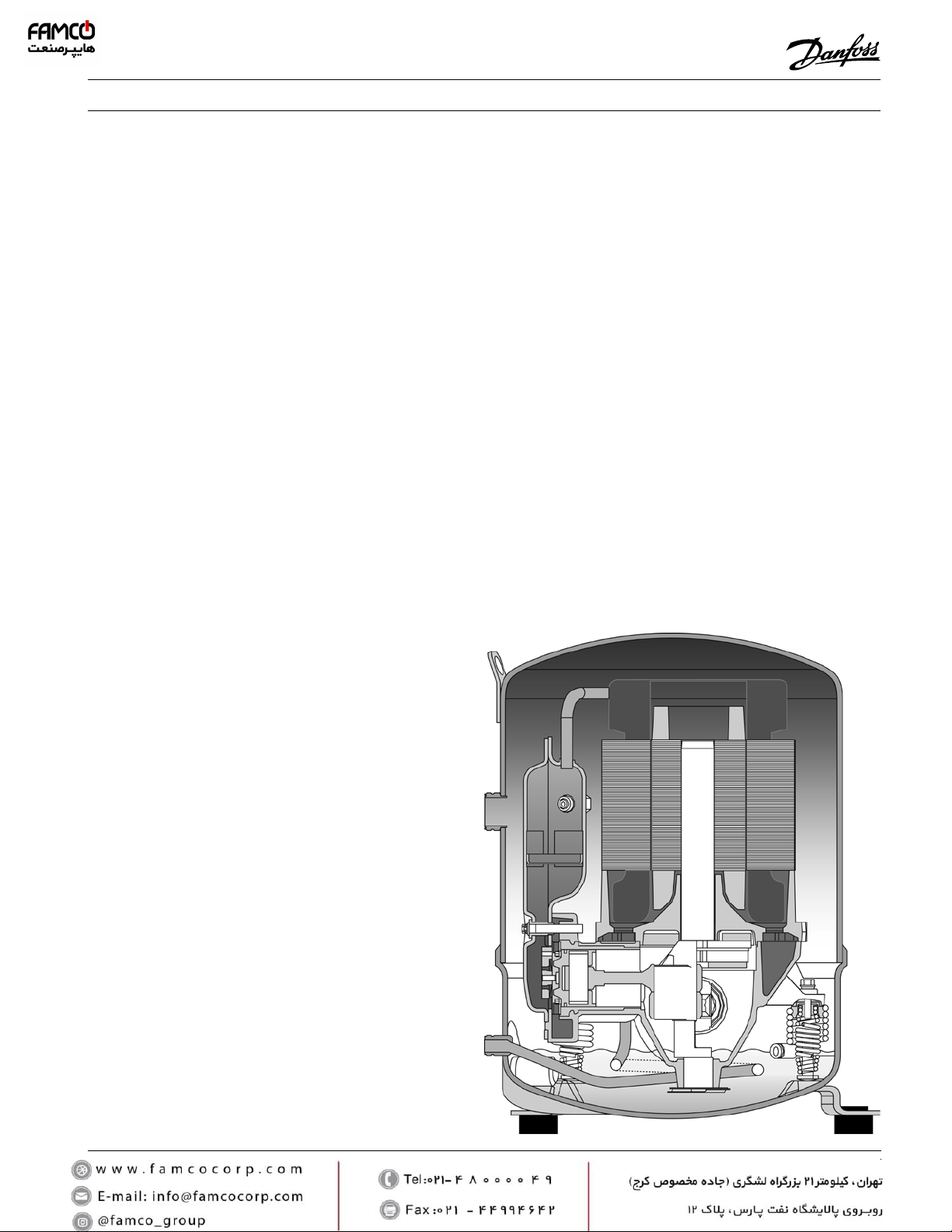
Maneurop® reciprocating compressors.......... 5
Compressor model designation ...................... 6
Code numbers (for ordering) ........................................... 6
Compressor reference (indicated on the compressor
nameplate).............................................................................. 6
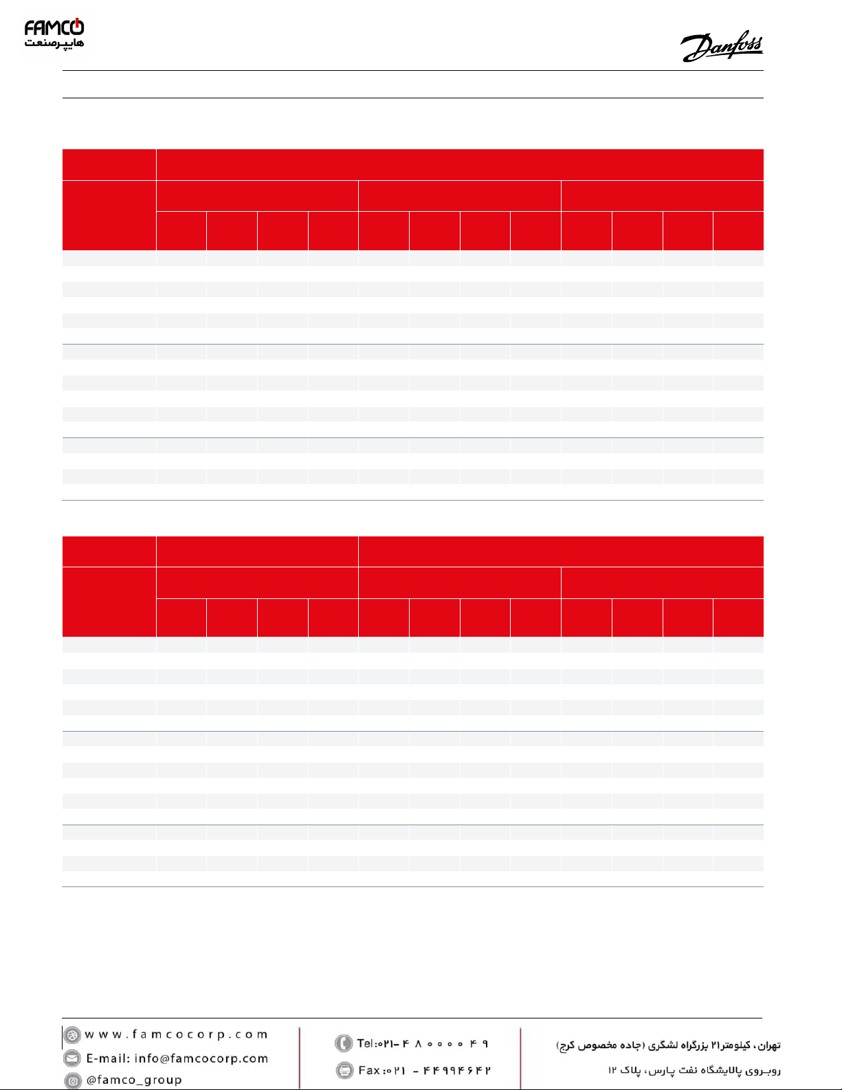
Specications.................................................... 7
Technical specications...................................................... 7
Approvals and certicates................................................. 7
Pressure equipment directive 2014/68/EU ................. 7
Low voltage directive 2014/35/EU................................. 7
Machinery directive 2014/30/EU.................................... 7
Internal free volume............................................................ 7
Nominal performance data for R404A and R22 ....... 8
Nominal performance data for R407C and R134a.... 9
Nominal performance data for R407A and R407F..10
Operating envelopes......................................11
Discharge temperature protection..............................12
Zeotropic refrigerant mixtures ......................................13
Phase shift.............................................................................13
Temperature glide..............................................................13
Dew temperature and Mean temperature for
R407A/C/F .............................................................................13
Outline drawings ............................................14
1 cylinder...............................................................................14
2 cylinders .............................................................................15
4 cylinders .............................................................................16
Electrical connections and wiring .................17
Single phase electrical characteristics ........................17
Nominal capacitor values and relays...........................17
Trickle circuit ........................................................................17
PSC wiring.............................................................................17
CSR wiring.............................................................................17
Suggested wiring diagrams............................................18
Three phase electrical characteristics .........................19
Winding resistance.............................................................19
Motor protection and suggested wiring diagrams19
Soft starters...........................................................................21
Voltage application range...............................................21
IP rating..................................................................................21
Refrigerants and lubricants........................... 22
General information ..........................................................22
R22...........................................................................................22
Alternatives R22, HFC retrot.........................................22
R407C......................................................................................23
R134a ......................................................................................23
R404A......................................................................................23
R507.........................................................................................23
R407A......................................................................................24
R407F ......................................................................................24
Hydrocarbons ......................................................................24
System design recommendations................. 25
Piping design .......................................................................25
Operating limits ..................................................................26
Operating voltage and cycle rate.................................27
Liquid refrigerant control and charge limit...............27
Sound and vibration management...............29
Sound .....................................................................................29
Vibration ................................................................................29
Installation and service..................................30
System cleanliness .............................................................30
Compressor handling, mounting and connection to
the system.............................................................................30
System pressure test .........................................................31
Leak detection.....................................................................31
Vacuum pull-down moisture removal........................31
Start-up ..................................................................................32
Ordering information and packaging...........34
Packaging..............................................................................34

Application guidelines
5FRCC.PC.004.A9.22
Maneurop® reciprocating compressors
Maneurop® reciprocating compressors from
Danfoss Commercial Compressors are specially
designed for applications with a wide range of
operating conditions. All components are of high
quality and precision in order to assure a long
product life.
Maneurop® MT and MTZ series compressors
are hermetic reciprocating type designed for
medium and high evaporating temperature
applications.
The positive benets of internal motor
protection, high eciency circular valve design
and high torque motors provide for a quality
installation.
MT & MTZ have the same mechanical and motor
design.
MT is charged with mineral oil while MTZ with
polyester oil.
These compressor ranges can be used with
a large choice of refrigerants according their
compatibility with the oil.
MTZ compressors can be used in new
installations and also to replace Maneurop® MTE
compressors in existing installations.
MT and MTZ compressors have a large internal
free volume that protects against the risk of
liquid hammering when liquid refrigerant enters
the compressor.
MT and MTZ compressors are fully suction-gas
cooled. This means that no additional compressor
cooling is required and allows the compressors
to be insulated with acoustic jackets, to
obtain lower sound levels, without the risk of
compressor overheating.
MT and MTZ compressors are available in 16
dierent models with displacement ranging
from 1.84 to 16.57 in3/rev. Seven dierent motor
voltage ranges are available for single and
three phase power supplies at 50 and 60 Hz.
All compressors are available in VE version (oil
equalisation + oil sight glass).

Application guidelines
6FRCC.PC.004.A9.22
Compressor model designation
Compressor reference
(indicated on the compressor
nameplate)
Code numbers (for ordering)
Compressor type
Polyolester oil
KBtu/h @ ARI.60Hz
Packaging type
I : single pack
M : industrial pack
(see ordering section)
Oil equalisation port
and threaded sight glass
Motor voltage code
1: 208-230V/1~/60Hz
3: 200-230V/3~/60Hz
4: 380-400 V/3~/50Hz & 460V/3~/60Hz
5: 220-240 V/1~/50Hz
6: 230 V/3~/50Hz
7: 500 V/3~/50Hz & 575V/3~/60Hz
9: 380 V/3~/60Hz
Oil equalisation port
and sight glass
Compressor
type
Generation index
Motor voltage code
1: 208-230V/1~/60Hz
3: 200-230V/3~/60 Hz
4: 380-400V/3~/50Hz & 460V/3~/60Hz
5: 220-240V/1~/50Hz
6: 230V/3~/50Hz
7: 500V/3~/50Hz & 575V/3~/60Hz
9: 380V/3~/60Hz
Polyolester oil
KBtu/h @ ARI.60Hz
Displacement code
D
Available code numbers are listed section “Ordering information and packaging”

Application guidelines
7FRCC.PC.004.A9.22
Specifications
Maneurop® MT/MTZ compressors comply with
the following approvals and certicates.
Certicates are listed on the product datasheets:
http://www.danfoss.com/odsg
Approvals and certicates
Pressure equipment
directive 2014/68/EU
Low voltage directive
2014/35/EU
Internal free volume
Technical specications
Compressor
model
Displacement Cyl.
number
Oil
charge
oz
Net
weight
lbs
Available motor voltage codes
Code in3/rev cfh at
3600 rpm 1345679
MT/MTZ018 JA 1.84 231 1 32 46 ●●●● -- -
MT/MTZ022 JC 2.33 291 1 32 46 ●●●●● -●
MT/MTZ028 JE 2.93 367 1 32 51 ●●●●● -○
MT/MTZ032 JF 3.29 411 1 32 53 ●●●●●○●
MT/MTZ036 JG 3.69 461 1 32 55 ●●●●●○●
MT/MTZ040 JH 4.14 518 1 32 57 ●●● -●- -
MT/MTZ044 HJ 4.65 581 2 61 77 ●●● -○○●
MT/MTZ050 HK 5.23 653 2 61 77 ●●● -●○●
MT/MTZ056 HL 5.87 733 2 61 82 ●●● -●●●
MT/MTZ064 HM 6.57 822 2 61 82 ●●● -●-●
MT/MTZ072 HN 7.38 922 2 61 88 -● ● -●-●
MT/MTZ080 HP 8.29 1036 2 61 88 -● ● -●-●
MT/MTZ100 HS 10.45 1306 4 132 132 -● ● -●●●
MT/MTZ125 HU 13.15 1643 4 132 141 -● ● -●●●
MT/MTZ144 HV 14.76 1845 4 132 148 -● ● -●●●
MT/MTZ160 HW 16.57 2071 4 132 148 -● ● -●●●
●Available in MT and MTZ ○Available in MTZ only
Products MT/ MTZ018 to 040 MT/ MTZ044 to 160
Manufacturer’s declaration contact Danfoss contact Danfoss
Products Volume (gallon)
Low side High side
1 cyl. 2.049 0.074
2 cyl. 4.525 0.166
4 cyl . 8.506 0.317
Products MT/ MTZ018 to 040 MT/ MTZ044 to 160
Refrigerating uids Group 2 Group 2
Category PED I II
Evaluation module no scope D1
Maximum/minimum allowable
temperature - TS 122°F > Ts > -31°F 122°F > Ts > -31°F
MT maximum allowable pressure - PS 267 psig 267 psig
MTZ maximum allowable pressure - PS 328 psig 328 psig
CE 0062 or CE 0038
(European Directive) All models
UL
(Underwriters Laboratories) All 60 Hz models
CCC
(China Compulsory Product Certication) Models code 4 and 5 under CC scope
EAC Eurasian conformity mark All models voltage code 4 and 5
Machinery directive
2014/30/EU Products MT/MTZ 018 to 040 MT/MTZ 044 to 160
Manufacturer's declaration contact Danfoss contact Danfoss

Application guidelines
8FRCC.PC.004.A9.22
Specications
Nominal performance data for R404A and R22
R22 Refrigeration Air conditioning
Compressor model
50 Hz, EN12900 ratings
To = 14°F, Tc = 113°F, SC = 0 F, SH = 18°F 50 Hz, ARI ratings
To = +45°F, Tc = 130°F, SC = 15°F, SH = 20°F 60 Hz, ARI ratings
To = +45°F, Tc = 130°F, SC = 15°F, SH = 20°F
Cooling
capacity
BTU/h
Power
input
kW
Current
input
A
E.E.R.
BTU/Wh
Cooling
capacity
BTU/h
Power
input
kW
Current
input
A
E.E.R.
BTU/Wh
Cooling
capacity
BTU/h
Power
input
kW
Current
input
A
E.E.R.
BTU/Wh
MT018-4 5770 1.00 2.27 5.77 13240 1.45 2073 9.13 15900 1.74 2.73 9.14
MT022-4 8500 1.29 2.55 6.59 18290 1.89 3.31 9.68 21980 2.27 3.31 9.68
MT028-4 12730 1.81 3.59 7.03 25190 2.55 4.56 9.88 30200 3.06 4.56 9.87
MT032-4 13480 2.11 3.73 6.39 27510 2.98 4.97 9.23 33040 3.58 4.97 9.23
MT036-4 16420 2.35 4.30 6.99 31640 3.37 5.77 9.39 37990 4.05 5.77 9.38
MT040-4 17820 2.67 4.86 6.67 35770 3.86 6.47 9.27 42900 4.63 6.47 9.27
MT044-4 16590 2.46 5.02 6.74 35900 3.53 6.37 10.17 43990 4.32 6.42 10.18
MT050-4 20030 2.94 5.53 6.81 41740 4.19 7.20 9.96 50140 5.04 7.26 9.95
MT056-4 21980 3.18 6.39 6.91 46930 4.58 8.19 10.25 56380 5.58 8.23 10.10
MT064-4 26450 3.64 7.03 7.27 53690 5.27 9.16 10.19 64330 6.32 9.33 10.18
MT072-4 29730 4.19 8.48 7.10 62120 6.12 10.98 10.15 74540 7.33 10.77 10.17
MT080-4 35360 4.89 9.52 7.23 70780 7.08 12.48 10.00 84910 8.50 12.34 9.99
MT100-4 38670 5.79 11.82 6.68 79860 7.98 14.59 10.01 95840 9.58 14.59 10.00
MT125-4 52080 7.55 12.28 6.90 103860 10.66 17.37 9.74 124610 12.8 17.37 9.74
MT144-4 58980 8.47 17.06 6.96 117200 11.95 22.75 9.81 140650 14.35 22.75 9.80
MT160-4 65490 9.49 16.81 6.90 130610 13.40 22.16 9.75 156760 16.08 22.16 9.75
To: Evaporating temperature at dew point (saturated suction temperature) SC: Subcooling
Tc: Condensing temperature at dew point (saturated discharge temperature) SH: Superheat
ARI capacity and power input data are +/- 5%
Asercom: Association of European Refrigeration Compressor and Controls Manufacturers
ARI: Air Conditioning and Refrigeration Institute
R404A Refrigeration
Compressor model
50 Hz, EN12900 ratings
To = 14°F, Tc = 113°F, SC = 0 F, SH = 18°F 50 Hz, ARI ratings
To = 20°F, Tc = 120°F, SC = 0°F, SH = 20°F 60 Hz, ARI ratings
To = 20°F, Tc = 120°F, SC = 0°F, SH = 20°F
Cooling
capacity
BTU/h
Power
input
kW
Current
input
A
E.E.R.
BTU/Wh
Cooling
capacity
BTU/h
Power
input
kW
Current
input
A
E.E.R.
BTU/Wh
Cooling
capacity
BTU/h
Power
input
kW
Current
input
A
E.E.R.
BTU/Wh
MTZ018-4* 6500 1.21 2.73 5.40 7100 1.31 2.86 5.42 9000 1.76 2.86 5.10
MTZ022-4* 9000 1.48 3.06 6.05 9700 1.62 3.24 5.97 12300 2.05 3.27 6.01
MTZ028-4* 11700 1.96 4.04 5.98 12600 2.15 4.30 5.89 16000 2.68 4.23 5.96
MTZ032-4* 13600 2.16 4.25 6.29 14600 2.37 4.56 6.15 17500 2.99 4.56 5.85
MTZ036-4* 15900 2.58 4.95 6.19 17100 2.83 5.33 6.03 20200 3.34 5.10 6.05
MTZ040-4* 18200 2.95 5.87 6.17 19400 3.25 6.30 5.98 23000 3.77 5.89 6.11
MTZ044-4* 18300 2.78 5.35 6.60 19800 3.02 5.68 6.54 24300 3.85 5.85 6.31
MTZ050-4* 21400 3.22 5.95 6.64 22900 3.50 6.33 6.54 28600 4.42 6.53 6.47
MTZ056-4* 22900 3.51 6.83 6.52 24800 3.85 7.26 6.44 32500 4.98 7.53 6.51
MTZ064-4* 27200 4.20 7.82 6.48 29400 4.60 8.35 6.38 36100 5.67 8.32 6.36
MTZ072-4* 30400 4.69 8.95 6.50 32700 5.12 9.51 6.40 40900 6.53 9.74 6.26
MTZ080-4* 35700 5.61 10.20 6.37 38200 6.14 10.95 6.23 46500 7.82 11.36 5.95
MTZ100-4* 41900 6.76 12.21 6.20 45000 7.36 12.95 6.12 52900 8.72 12.79 6.07
MTZ125-4* 53600 8.44 13.79 6.35 57500 9.22 14.87 6.23 68300 11.37 15.41 6.00
MTZ144-4* 63100 9.78 16.29 6.46 67300 10.66 17.48 6.32 80500 13.00 17.94 6.19
MTZ160-4* 69300 11.08 18.26 6.26 74100 12.10 19.65 6.12 87400 14.74 20.18 5.93
* 50 Hz, EN12900 data for indicated models are Asercom certied R404A data are also valid for refrigerant R507

Application guidelines
9FRCC.PC.004.A9.22
Specications
Nominal performance data for R407C and R134a
R407C Air conditioning
Compressor model
50 Hz, EN12900 ratings
To = +41°F, Tc = 122°F, SC = 0F, SH = 18°F 50 Hz, ARI ratings
To = +45°F, Tc = 130°F, SC = 15°F, SH = 20°F 60 Hz, ARI ratings
To = +45°F, Tc = 130°F, SC = 15°F, SH = 20°F
Cooling
capacity
BTU/h
Power
input
kW
Current
input
A
E.E.R.
BTU/Wh
Cooling
capacity
BTU/h
Power
input
kW
Current
input
A
E.E.R.
BTU/Wh
Cooling
capacity
BTU/h
Power
input
kW
Current
input
A
E.E.R.
BTU/Wh
MTZ018-4* 11840 1.27 2.73 9.32 13140 1.38 2.86 9.52 17240 1.73 2.82 9.96
MTZ022-4* 15530 1.71 3.27 9.08 17130 1.86 3.47 9.21 21430 2.26 3.45 9.48
MTZ028-4* 20070 2.17 4.30 9.25 22320 2.36 4.57 9.46 28050 2.82 4.41 9.95
MTZ032-4* 22700 2.43 4.57 9.34 25020 2.65 4.90 9.44 30680 3.20 4.80 9.59
MTZ036-4* 25630 2.93 5.58 8.75 28260 3.21 5.99 8.80 34100 3.90 5.78 8.74
MTZ040-4* 29560 3.40 6.46 8.69 32700 3.71 6.92 8.81 40000 4.46 6.69 8.97
MTZ044-4* 31160 3.12 5.84 9.99 34470 3.38 6.18 10.20 43450 4.25 6.34 10.22
MTZ050-4* 35560 3.69 6.51 9.64 39350 4.01 6.95 9.81 48160 4.87 7.06 9.89
MTZ056-4* 39860 4.02 7.45 9.92 44370 4.37 7.91 10.15 54780 5.40 8.03 10.14
MTZ064-4* 45600 4.61 8.35 9.89 50680 5.02 8.91 10.10 61710 6.14 9.01 10.05
MTZ072-4* 52290 5.42 9.85 9.65 58190 5.87 10.48 9.91 70920 7.30 10.61 9.72
MTZ080-4* 59320 6.29 11.31 9.43 65970 6.83 12.08 9.66 78050 8.24 11.99 9.47
MTZ100-4* 69900 7.38 13.05 9.47 77470 8.00 13.83 9.68 96310 9.86 14.22 9.77
MTZ125-4* 91740 9.48 15.14 9.68 101640 10.32 16.28 9.85 121570 12.83 18.07 9.48
MTZ144-4* 101600 10.68 17.55 9.51 112830 11.59 18.80 9.74 139590 14.42 19.81 9.68
MTZ160-4* 116350 12.40 20.08 9.38 129040 13.46 21.50 9.59 154330 16.64 22.46 9.27
* 50 Hz, EN12900 data for indicated models are Asercom certied
R134a Refrigeration Air conditioning
Compressor model
50 Hz, EN12900 ratings
To = 14°F, Tc = 113°F, SC = 0 F, SH = 18°F 50 Hz, ARI ratings
To = +45°F, Tc = 130°F, SC = 15°F, SH = 20°F 60 Hz, ARI ratings
To = +45°F, Tc = 130°F, SC = 15°F, SH = 20°F
Cooling
capacity
BTU/h
Power
input
kW
Current
input
A
E.E.R.
BTU/Wh
Cooling
capacity
BTU/h
Power
input
kW
Current
input
A
E.E.R.
BTU/Wh
Cooling
capacity
BTU/h
Power
input
kW
Current
input
A
E.E.R.
BTU/Wh
MTZ018-4 3670 0.69 1.92 5.33 8640 0.99 2.19 8.73 10370 1.19 2.29 8.73
MTZ022-4 4800 0.82 2.16 5.89 11380 1.20 2.51 9.50 13660 1.44 2.62 9.50
MTZ028-4 6220 1.02 2.83 6.10 14400 1.53 3.30 9.40 17280 1.84 3.44 9.40
MTZ032-4 7090 1.25 3.33 5.68 16750 1.87 3.94 8.95 20110 2.25 4.11 8.95
MTZ036-4 9390 1.45 3.32 6.48 20530 2.13 4.09 9.61 24640 2.56 4.26 9.61
MTZ040-4 9940 1.61 3.81 6.18 21650 2.34 4.89 9.27 25980 2.80 5.10 9.27
MTZ044-4 9980 1.49 4.05 6.68 23340 2.22 4.73 10.51 28010 2.67 4.94 10.51
MTZ050-4 11480 1.80 4.32 6.37 27160 2.63 5.20 10.32 32600 3.16 5.43 10.32
MTZ056-4 12030 1.88 5.31 6.39 29440 2.85 6.17 10.34 35330 3.42 6.44 10.34
MTZ064-4 14300 2.17 5.71 6.60 34340 3.27 6.81 10.51 41210 3.92 7.10 10.51
MTZ072-4 16630 2.50 6.67 6.64 39420 3.78 7.99 10.42 47300 4.54 8.33 10.42
MTZ080-4 19980 2.93 7.22 6.82 45280 4.36 8.84 10.39 54340 5.23 9.21 10.39
MTZ100-4 22580 3.65 8.67 6.19 52760 5.28 10.25 9.99 63310 6.34 10.69 9.99
MTZ125-4 28340 4.17 8.35 6.79 64670 6.29 10.81 10.27 77600 7.55 11.27 10.28
MTZ144-4 36620 5.40 11.02 6.78 80360 7.83 13.79 10.26 96430 9.40 14.39 10.26
MTZ160-4 40610 5.84 11.37 6.96 88010 8.58 14.68 10.26 105600 10.30 15.31 10.25
To: Evaporating temperature at dew point (saturated suction temperature) SC: Subcooling
Tc: Condensing temperature at dew point (saturated discharge temperature) SH: Superheat
ARI capacity and power input data are +/- 5%
Asercom: Association of European Refrigeration Compressor and Controls Manufacturers
ARI: Air Conditioning and Refrigeration Institute

Application guidelines
10 FRCC.PC.004.A9.22
Specications
Nominal performance data for R407A and R407F
R407A Refrigeration
Compressor model
50 Hz, EN12900 ratings
To = 14°F, Tc = 113°F, SC = 0 F, SH = 18°F 50 Hz, ARI ratings
To = 20°F, Tc = 120°F, SC = 0°F, SH = 20°F 60 Hz, ARI ratings
To = 20°F, Tc = 120°F, SC = 0°F, SH = 20°F
Cooling
capacity
BTU/h
Power
input
kW
Current
input
A
E.E.R.
BTU/Wh
Cooling
capacity
BTU/h
Power
input
kW
Current
input
A
E.E.R.
BTU/Wh
Cooling
capacity
BTU/h
Power
input
kW
Current
input
A
E.E.R.
BTU/Wh
MTZ018-4 5900 1.02 2.46 5.81 6600 1.12 2.58 5.91 8000 1.35 2.69 5.91
MTZ022-4 8200 1.26 2.75 6.49 9100 1.39 2.91 6.50 10900 1.67 3.04 6.50
MTZ028-4 10700 1.67 3.63 6.41 11900 1.85 3.87 6.41 14200 2.22 4.04 6.41
MTZ032-4 12400 1.84 3.82 6.74 13700 2.04 4.10 6.70 16400 2.45 4.28 6.70
MTZ036-4 14500 2.19 4.45 6.64 16000 2.43 4.80 6.56 19200 2.92 5.00 6.56
MTZ040-4 16700 2.51 5.28 6.63 18300 2.80 5.67 6.51 21900 3.37 5.92 6.51
MTZ044-4 16700 2.36 4.81 7.08 18500 2.60 5.11 7.12 22200 3.12 5.33 7.12
MTZ050-4 19500 2.73 5.35 7.13 21500 3.01 5.70 7.14 25800 3.61 5.94 7.14
MTZ056-4 20900 2.98 6.14 7.00 23200 3.30 6.53 7.03 27800 3.96 6.81 7.03
MTZ064-4 24800 3.57 7.04 6.95 27500 3.95 7.52 6.95 33000 4.75 7.84 6.95
MTZ072-4 27800 3.98 8.05 6.98 30700 4.40 8.56 6.97 36800 5.28 8.92 6.97
MTZ080-4 32600 4.76 9.17 6.84 35800 5.28 9.86 6.78 43000 6.34 10.28 6.78
MTZ100-4 38200 5.74 10.98 6.66 42100 6.32 11.65 6.67 50600 7.59 12.16 6.67
MTZ125-4 48900 7.17 12.40 6.82 53800 7.93 13.38 6.79 64600 9.52 13.96 6.79
MTZ144-4 57600 8.32 14.65 6.92 63100 9.18 15.73 6.87 75700 11.03 16.41 6.87
MTZ160-4 63200 9.42 16.42 6.71 69400 10.43 17.69 6.65 83300 12.52 18.45 6.65
To: Evaporating temperature at dew point (saturated suction temperature) SC: Subcooling
Tc: Condensing temperature at dew point (saturated discharge temperature) SH: Superheat
R407F Refrigeration
Compressor model
50 Hz, EN12900 ratings
To = 14°F, Tc = 113°F, SC = 0 F, SH = 18°F 50 Hz, ARI ratings
To = 20°F, Tc = 120°F, SC = 0°F, SH = 20°F 60 Hz, ARI ratings
To = 20°F, Tc = 120°F, SC = 0°F, SH = 20°F
Cooling
capacity
BTU/h
Power
input
kW
Current
input
A
E.E.R.
BTU/Wh
Cooling
capacity
BTU/h
Power
input
kW
Current
input
A
E.E.R.
BTU/Wh
Cooling
capacity
BTU/h
Power
input
kW
Current
input
A
E.E.R.
BTU/Wh
MTZ018-4 6300 1.08 2.53 5.82 7100 1.19 2.66 5.96 8500 1.43 2.78 5.96
MTZ022-4 8700 1.33 2.83 6.52 9700 1.48 3.01 6.57 11600 1.77 3.14 6.57
MTZ028-4 11300 1.76 3.74 6.45 12700 1.96 4.00 6.48 15200 2.35 4.17 6.48
MTZ032-4 13200 1.94 3.93 6.78 14600 2.16 4.24 6.77 17600 2.59 4.42 6.77
MTZ036-4 15400 2.32 4.58 6.67 17100 2.58 4.96 6.63 20500 3.10 5.17 6.63
MTZ040-4 17600 2.65 5.43 6.66 19500 2.96 5.86 6.58 23400 3.55 6.11 6.58
MTZ044-4 17700 2.49 4.95 7.12 19900 2.76 5.28 7.20 23800 3.31 5.51 7.20
MTZ050-4 20700 2.90 5.50 7.14 23000 3.21 5.88 7.18 27600 3.85 6.14 7.18
MTZ056-4 22200 3.16 6.31 7.03 24900 3.51 6.75 7.09 29800 4.21 7.04 7.09
MTZ064-4 26400 3.78 7.23 6.99 29500 4.20 7.76 7.03 35400 5.03 8.10 7.03
MTZ072-4 29500 4.21 8.27 7.00 32900 4.67 8.84 7.04 39400 5.60 9.22 7.04
MTZ080-4 34600 5.04 9.43 6.87 38400 5.60 10.18 6.86 46100 6.72 10.62 6.85
MTZ100-4 40600 6.07 11.28 6.69 45200 6.71 12.04 6.74 54300 8.05 12.56 6.74
MTZ125-4 51900 7.58 12.75 6.85 57700 8.41 13.83 6.86 69200 10.09 14.42 6.86
MTZ144-4 61100 8.78 15.06 6.96 67600 9.73 16.25 6.95 81100 11.67 16.95 6.95
MTZ160-4 67100 9.95 16.88 6.75 74300 11.04 18.27 6.73 89200 13.25 19.06 6.73
To: Evaporating temperature at dew point (saturated suction temperature) SC: Subcooling
Tc: Condensing temperature at dew point (saturated discharge temperature) SH: Superheat
Asercom: Association of European Refrigeration Compressor and Controls Manufacturers
ARI: Air Conditioning and Refrigeration Institute

Application guidelines
11FRCC.PC.004.A9.22
Operating envelopes
MTZ - R407C at DEW point
MTZ - R134a
MTZ - R404A / R507
MT - R22 - R417A
160
80
-20
Condensing temperature (F)
Evaporating temperature (F)
-10 0 10 20 30 40 50 60 70
150
140
130
120
110
100
90
S.H. = 54F
S.H. = 20F
160
90
-10
Condensing temperature (F)
Evaporating temperature (F)
100
110
120
130
140
150
0 10 20 30 40 50 60 70
S.H. = 54F
S.H. = 20F
150
80
-30
Condensing temperature (F)
Evaporating temperature (F)
90
100
110
120
130
140
-20 -10 0 10 20 30 40 50 60
S.H. = 54F
S.H. = 20F
160
170
150
140
130
120
110
100
90
80
-10-20 0102030 40 50 60 70 80
C
ondensing temperature (°F)
Evaporating temperature (°F)
MTZ R134a
SH 18°F
RGT 68°F

Application guidelines
12 FRCC.PC.004.A9.22
Operating envelopes
MTZ – R407A at Dew Point
MTZ – R407F at Dew Point
150
80
-30
Condensing temperature (F)
Evaporating temperature (F)
90
100
110
120
130
140
-20 -10 0 10 20 30 40 50 60
RGT 68F
S.H. = 18F
150
80
-30
Condensing temperature (F)
Evaporating temperature (F)
90
100
110
120
130
140
-20 -10 0 10 20 30 40 50 60
RGT 68F
S.H. = 18F
Discharge temperature
protection
Even when the motor windings are protected
against overheating by the internal motor
protection, the compressor discharge gas
temperature could exceed the maximum allowed
value of 275°F when the compressor is operated
outside its application envelope. The most
eective protection against too high discharge
gas temperature is to mount a discharge
gas thermostat. An accessory kit is available
from Danfoss which includes the thermostat,
mounting bracket and insulation.
The thermostat must be attached to the
discharge line as indicated below at no more
than 5.90 inch from the discharge connection.
Thermostat
Insulation
Bracket
Discharge line

Application guidelines
13FRCC.PC.004.A9.22
Operating envelopes
Refrigerant mixtures can be either zeotropic or
azeotropic.
An azeotropic mixture (like R502 or R507)
behaves like a pure refrigerant. During a phase
transition (from vapor to liquid or from liquid to
vapor) the composition of vapor and liquid stays
the same.
In a zeotropic mixture (like R407C) on the other
hand the composition of vapor and liquid
changes during the phase transition. When the
eect of this phase transition is very small, the
mixture is often called a near-azeotropic mixture.
R404A is such a near-azeotropic mixture.
The composition change causes phase shift and
temperature glide.
Phase shift
Temperature glide
Dew temperature and Mean
temperature for R407A/C/F
In system components where both vapor and
liquid phase are present (evaporator, condenser,
liquid receiver), the liquid phase and vapor phase
do not have the same composition. In fact both
phases form two dierent refrigerants. Therefore
zeotropic refrigerants need some special
attention. Zeotropic refrigerants must always be
charged in liquid phase. Flooded evaporators
and suction accumulators should not be applied
in systems with zeotropic refrigerants. This also
applies to near-azeotropic mixtures.
During the evaporating process and the
condensing process at constant pressure,
the refrigerant temperature will decrease
in the condenser and rise in the evaporator.
Therefore when speaking about evaporating
and condensing temperatures, it is important to
indicate whether this is a dew point temperature
or a mean point value. In the gure below, the
dotted lines are lines of constant temperature.
They do not correspond to the lines of constant
pressure.
Points A and B are dew point values. These are
temperatures on the saturated vapor line.
Points C and D are mean point values. These are
temperatures which correspond more or less with
the average temperature during the evaporating
and condensing process. For the same cycle,
mean point temperatures are typically about
3.6°F lower than dew point temperatures.
According to Asercom recommendations,
Danfoss Commercial Compressors uses dew
point temperatures for selection tables and
application envelopes etc.
To obtain exact capacity data at mean point
temperatures, the mean point temperatures
must be converted to dew point temperatures
with help of refrigerant data tables from the
refrigerant manufacturer.
Zeotropic refrigerant
mixtures

Application guidelines
14 FRCC.PC.004.A9.22
Outline drawings
1 cylinder
Rotolock connections size Pipe sizing Rotolock valve
Suction Discharge Suction Discharge Suction Discharge
MT/MTZ018-022 (3/4/5/6/9)-028 (3/4/5/6) 1" 1" 1/2" 3/8" V06 V01
MT/MTZ022/1-028/1-032 - 036 - 040 1 1/4" 1" 5/8" 1/2" V09 V06
2.68”
10.35”
LP gauge
port 1/4”
(schrader)
13.11” (1)
14.02” (2)
3.86”
2.68”
0.98” 3.23”
Ø 8.82”
2.68”
6.26”
5.55”
4.65”
4.29”
0.67”
17°
35° 33°
1.54”
4.84”
Suction: 5.59” (1) / 5.79” (2)
Discharge: 5.59”
Threaded oil
sight glass
oil equalization
3/8”
Suction rotolock
1” (1)
1 1/4” (2)
Discharge rotolock
1”
Mounting hole for PTC crankcase heater
Silent bloc
0.91
”
Bolt HM8-40
Ø 1.25”
0.59”
Terminal box
IP rating: 55 (with cable gland)
Spade connectors
1/4" AMP-AWE
Earth M4-12
Ø 0.83 in
Knock-out Ø 0.83 in
Model Code
1345679
MT/MTZ018 (1) (1) (1) (1) - - -
MT/MTZ022 (2) (1) (1) (1) (1) - (1)
MT/MTZ028 (2) (1) (1) (1) (1) - (1)
MT/MTZ032 (2) (2) (2) (2) (2) (2) (2)
MT/MTZ036 (2) (2) (2) (2) (2) (2) (2)
MT/MTZ040 (2) (2) (2) - (2) - -

Application guidelines
15FRCC.PC.004.A9.22
Outline drawings
2 cylinders
Rotolock connections size Pipe sizing Rotolock valve
Suction Discharge Suction Discharge Suction Discharge
MT/MTZ044 - 050 - 056 - 064 - 072 1 3/4" 1 1/4" 7/8" 3/4" V07 V04
MT/MTZ080 1 3/4" 1 1/4" 1 1/8" 3/4" V02 V04
16.26"
Ø 11.34"
Schrader 1/4"
Suction rotolock
1 3/4"
Mounting hole for
PTC crankcase heater
Threaded oil sight glass
Discharge rotolock
1 1/4"
Oil equalization
3/8"
3.86"(1)
4.61"(2)
9.92"
0.79"
Suction 7.05"
Discharge 6.93"
0.83"
6.14"
6.73"
8°
38°
2.36"
5.71"
8°
4.92"
7.40" (1) / 7.72" (2)
3.78"
2.91"
2.68"
10.43"
3.23"(2) /3.86"(1)
Terminal box for model (1)
Spade connec
tors
1/4" AM
P-AWE
Earth M4-12
Ø 0.83 in
Knock-out Ø 0.83 in
IP rating: 55 (with cable gland)
Silent bloc
0.91
”
Bolt HM8-40
Ø 1.25”
0.59”
Terminal box for model (2)
IP rating: 54 (with cable gland)
Model Code
134679
MT/MTZ044 (1) (1) (1) (2) (1) (1)
MT/MTZ050 (2) (1) (1) (2) (1) (1)
MT/MTZ056 (2) (1) (1) (2) (1) (1)
MT/MTZ064 (2) (1) (1) (2) - (1)
MT/MTZ072 - (1) (1) (2) - (1)
MT/MTZ080 - (2) (1) (2) - (1)

Application guidelines
16 FRCC.PC.004.A9.22
Outline drawings
4 cylinders
Rotolock connections size Pipe sizing Rotolock valve
Suction Discharge Suction Discharge Suction Discharge
MT/MTZ100 - 125 - 144 - 160 1 3/4" 1 1/4" 1 1/8" 3/4" V02 V04
Ø 13.86"
21.18" (2)
20.39" (1)
4.61"
6.10"
9.13"
3.90"
Oil equalisation
3/8"
Mounting hole for
PTC crankcase heater
15°
15°
15°
9.69"
8.07"
155°
9.69"
Suction rotolock
1 3/4"
Discharge rotolock
1 1/4"
9.17"
8.27"
4.92"
8.23"
3.86"
3.74"
Threaded oil
sight glass
Schrader 1/4 "
1) MT/MTZ 100-125 3/4/6/7/9
2) MT/MTZ 144-160 3/4/6/7/9
Silent bloc
0.75” 1.18”
IP rating: 54 (with cable gland)
Terminal box

Application guidelines
17FRCC.PC.004.A9.22
Electrical connections and wiring
The trickle circuit provides the facility of heating
the compressor crankcase by feeding a small
current to the auxiliary winding and the run
capacitor (See the drawings page 14.)
By using PSC or CSR starting systems, compressor
models MT / MTZ 018 - 022 can be operated
without crankcase heaters as the heater function
is provided by the trickle circuit.
For the larger single phase compressor models
MT / MTZ 028 - 064, the use of the PTC crankcase
heater is recommended.
PSC wiring may be used for refrigerant circuits
with capillary tubes or expansion valves with
bleed ports. Pressure equalization must be
ensured before start-up because of the low
starting torque characteristics of this system.
CSR wiring provides additional motor torque
at start-up, by the use of a start capacitor in
combination with the run capacitor. This system
can be used for refrigerant circuits with capillary
tubes or expansion valves. The start capacitor is
only connected during the starting operation, a
potential relay is used to disconnect it after the
start sequence.
Some applications with high dierential pressure
can require a very high starting torque. For such
cases the CSR starting kit can be converted to
a very high starting torque kit by an additional
start capacitor of 100 μF parallel to the start
capacitor of the CSR kit. This conguration
can also be used to reduce erratic starting at
unfavorable conditions such as very low ambient
temperature or weak voltage.
Nominal capacitor values
and relays
Trickle circuit
PSC wiring
CSR wiring
Single phase electrical
characteristics
* PSC: Permanent Split Capacitor
CSR: Capacitor Start Run
(1) Run capacitors: 440 volts
(2) Start capacitors: 330 Volts
LRA - Locked Rotor
Current (A) MCC - Maximum
Continuous Current (A) Winding resistance (Ω)
( ± 7 % at 68° F)
Motor Code 1 5 1 5 1 5
Winding run start run start
MT/MTZ018 51 40 13 10 1.32 4.16 1.32 3.75
MT/MTZ022 49.3 41 17 15 1.18 2.26 1.32 3.75
MT/MTZ028 81 51 25 20 0.67 1.80 1.05 3.19
MT/MTZ032 84 70 26.5 20 0.62 2.84 0.78 4.14
MT/MTZ036 84 60 30 22 0.62 2.84 0.78 4.14
MT/MTZ040 99 - 34 - 0.53 1.83 - -
MT/MTZ044 97 - 31 - 0.45 1.90 - -
MT/MTZ050 114 - 36 - 0.37 1.79 - -
MT/MTZ056 136 - 42.5 - 0.32 1.61 - -
MT/MTZ064 143 - 46 - 0.32 2.10 - -
Models
PSC/CSR* CSR only
Run capacitors (1) Start capacitors (2) Start relay
(A) µF (C) µF (B) µF
50 Hz
MT/MTZ018 JA-5 20 10 100
3ARR3J4A4
/RVA6AMKL
MT/MTZ022 JC-5 20 10 100
MT/MTZ028 JE-5 20 10 100
MT/MTZ032 JF-5 25 10 135
MT/MTZ036 JG-5 25 10 135
60 Hz
MT/MTZ018 JA-1 15 10 100
3ARR3J4A4
/RVA6AMKL
MT/MTZ022 JC-1 30 15 100
MT/MTZ028 JE-1 25 25 135
MT/MTZ032 JF-1 25 20 100
MT/MTZ036 JG-1 25 20 100
MT/MTZ040 JH-1 35 20 100
MT/MTZ044 HJ-1 30 15 135
MT/MTZ050 HK-1 30 15 135
MT/MTZ056 HL-1 35 20 200
MT/MTZ064 HM-1 30 25 235

Application guidelines
18 FRCC.PC.004.A9.22
Electrical connections and wiring
Suggested wiring diagrams
Single phase - PSC wiring
with trickle circuit
Single phase - CSR wiring
with trickle circuit
IOL Motor protector
A+C Run capacitors
B Start capacitor
C Common
S Start winding (auxiliary)
R Run winding (main)
Capacitors A and C can be replaced by a
single capacitor of size A + C
B capacitor delivered in two parts for
MT(Z)56 & 64-1
Single phase - CSR wiring
without trickle circuit
IOL Motor protector
A & C Run capacitors
B Start capacitor
C Common
S Start winding (auxiliary)
R Run winding (main)
IOL Motor protector
A & C Run capacitors
C Common
S Start winding (auxiliary)
R Run winding (main)
230 V
220 kΩ - 1 W
A µF
CIOL
SR
C µF
Thermostat
230 V
220 kΩ - 1 W
15 kΩ - 1 W
A µF
C
IOL
S
2
1
5
R
C µF
B µF
Thermostat
Start relay
230 V
Thermostat
BµF
Start capacitor
Start Relay
5
2
1
15 kΩ -1 w
C
SR
IOL
AµF
Run capacitor
CµF
Run capacitor

Application guidelines
19FRCC.PC.004.A9.22
Electrical connections and wiring
Motor protection and
suggested wiring diagrams
The 3-phase compressors are protected by
an internal motor protector, connected to
the neutral point of the star connected stator
windings, the protector cuts out all 3-phases
simultaneously.
Note: once the overload protector has tripped it
may take up to 3 hours to reset and restart the
compressor.
For all 3-phase compressors, a PTC crankcase
heater is required.
Three phase electrical characteristics
Motor Code
LRA - Locked Rotor
Current (A) MCC - Maximum
Continuous Current (A) Winding resistance (Ω)
( ± 7 % at 68° F)
346793467934679
MT/MTZ018 38 20 - - - 9 5 - - - 2.29 9.18 3.34 - -
MT/MTZ022 38 20 30 - 22.5 11 6 8.5 - 6.5 2.29 11.6* 3.34 - 7.15
MT/MTZ028 57 23 41 - 32 16 7.5 11.5 - 8.5 1.38 6.17 1.18 - 4.62
MT/MTZ032 60 25 44 22 35 18 8 13 5.5 9 1.29 6.32 1.97 9.90 3.33
MT/MTZ036 74 30 74 26 35 17 9 17 7 9.5 1.08 5.43 1.08 7.76 3.33
MT/MTZ040 98 38 74 - - 22 10 18 - - 0.87 3.97 1.08 - -
MT/MTZ044 115 48.5 77 44 78 22 9.5 16 8.5 13 0.74 3.22 1.13 5.83 1.68
MT/MTZ050 115 48.5 77 44 78 25 11.5 19 10 13.5 0.72 3.35 1.39 5.83 1.68
MT/MTZ056 130 64 105 50 72 24 12 23 11 15 0.55 2.39 0.76 3.86 1.64
MT/MTZ064 137 64 124 - 72 29 14 25 - 17.5 0.57 2.39 0.76 - 1.64
MT/MTZ072 135 80 143 - 100 30 17 27 - 18.5 0.55 1.90 0.56 - 1.32
MT/MTZ080 140 80 132 - 102 36 19 29 - 22.5 0.48 1.90 0.56 - 1.30
MT/MTZ100 157 90 126 62 110 43 22 35 17 26 0.50 1.85 0.67 3.10 1.26
MT/MTZ 125 210 105 170 75 150 54 27 43 22 30 0.38 1.57 0.43 2.51 0.84
MT/MTZ 144 259 130 208 90 165 64 36 51 25 40 0.27 1.19 0.37 2.00 0.72
MT/MTZ 160 259 130 208 99 165 70 36 51 29 46 0.27 1.19 0.37 1.76 1.10
* Motor windings made of Aluminium wires.
Winding resistance Winding resistance is the resistance between
indicated terminal pins at 68°F (resistance value
+/- 7%).
Winding resistance is generally low and it
requires adapted tools for precise measurement.
Use a digital ohm-meter, a ‘4 wires’method and
measure under stabilised ambient temperature.
Winding resistance varies strongly with winding
temperature ; If the compressor is stabilised at a
dierent value than 68°F, the measured resistance
must be corrected with following formula:
a + tamb
Rtamb = R68°F
a + t68°F
t68°F: reference temperature = 68°F
tamb: temperature during measurement (°F)
R68°F: winding resistance at 68°F
Ramb: winding resistance at tamb
coecient a= 234.5 copper wires motor
coecient a= 232.6 aluminium wires motor

Application guidelines
20 FRCC.PC.004.A9.22
Electrical connections and wiring
Suggested wiring diagram with
one shot pump-down cycle and
safety lock-out relay
Control device ................................................ TH
Optional short cycle timer (3 min) ..... 180 s
Control relay .................................................... KA
Liquid Solenoid valve ............................... LLSV
Compressor contactor ................................ KM
Safety lock out relay ...................................... KS
Pump-down control & LP switch............... LP
H.P. switch ........................................................ HP
Fused disconnect .......................................... Q1
Fuses ................................................................... F1
Compressor motor .......................................... M
Discharge gas thermostat ....................... DGT
M
DGT
HP
180 s
TH
LP
CONTROL CIRCUIT
F1F1
KM
KM
KM
KA KA
A1
A2
A3
KA
KA
KS
KS
KS
L1 L3 L2
Q1
T1
T3
T2
LLSV KS
Wiring diagram without pump-
down cycle
Control device ................................................ TH
Optional short cycle timer (3 min) ..... 180 s
Control relay .................................................... KA
Compressor contactor ................................ KM
Safety lock out relay ...................................... KS
High pressure switch .................................... HP
Low pressure switch....................................... LP
Fused disconnect .......................................... Q1
Fuses ................................................................... F1
Compressor motor .......................................... M
Discharge gas thermostat ....................... DGT
KM
L1 L3 L2
Q1
CONTROL CIRCUIT
F1F1
KM KA
KA KS
KS
KS
LP
HP
DGT
TH
180 s
85 52 019 - A
T1 T2
M
T3
KA KA
A1
A2
A3
This manual suits for next models
1
Table of contents
Popular Air Compressor manuals by other brands

Powermate
Powermate 200-2645 Operator's & parts manual

GEA
GEA Searle NSQ Series Installation and maintenance instructions

Campbell Hausfeld
Campbell Hausfeld CE7000 Series operating instructions

DeWalt
DeWalt DXCMLA1983054 instruction manual

Aerfast
Aerfast AC09210 operating manual

Miller Electric
Miller Electric AC Generator/Air Compressor Specification sheet

Clarke
Clarke SHHHAIR 50/24 Operation & maintenance instructions

VIAIR
VIAIR 00190 user manual

SNOWJOE
SNOWJOE SUNJOE 24V-AJC-LTE Operator's manual

Gardner Denver
Gardner Denver TR20 Rear CW Installation operating & maintenance manual

GEA
GEA Grasso M-Series operating manual

Thomas
Thomas Renegade TG-550H Owner's Manual and Operating Instructions