Fancom AURA 70 User manual

g

N.B.: The original, authentic version of this manual is the English version produced by Fancom B.V. or one of its
daughter companies (referred to further as Fancom). Any modifications introduced to this manual by third parties
have neither been checked nor approved by Fancom. Modifications are taken by Fancom to include translations
into languages other than English and the insertion and/or deletion of text and/or illustrations to/from the original
contents. Fancom cannot be held liable for any damages, injury, guarantee claims and other claims relating to this
type of modification, in as far as these modifications result in a content that differs from the original English
version of this manual produced by Fancom. For the latest information about product installation and operation,
please contact the customer service dept. and/or the technical service dept. of the Fancom concerned. In spite of
the care taken when compiling this manual, if you should discover any errors, please inform Fancom B.V. in
writing. Fancom B.V., PO Box 7131, 5980 AC Panningen (the Netherlands).
Copyright © 2017 Fancom B.V.
Panningen (the Netherlands)
All rights reserved. Nothing from this manual may be copied, distributed or translated into other languages, partly
or wholly, without express prior written permission from Fancom. Fancom reserves the right to modify this manual
without notice. Fancom can give no guarantee, neither implicit nor explicit, for this manual. All risks are for the
user.
This manual has been compiled with the utmost care. If, however, you should discover an error, please inform
Fancom B.V.
Art.Nr. 5911993
GB170112

Aura 70
Table of contents
i
1. General introduction .................................................................................................................................. 1
1.1 Documentation with the control computer....................................................................................... 1
1.2 How to use this manual .................................................................................................................. 1
1.3 Fancom Sales & Service Center..................................................................................................... 1
1.4 Safety instructions and warnings.................................................................................................... 2
2. Aura 70 ........................................................................................................................................................ 3
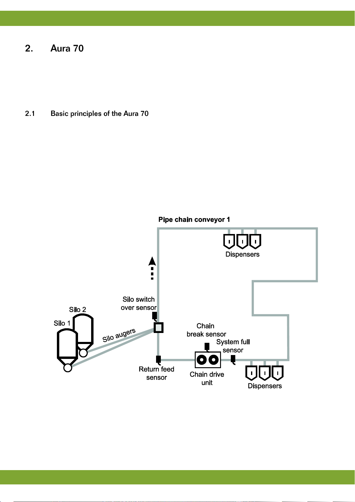
2.1 Basic principles of the Aura 70....................................................................................................... 3
2.2 Schematic view for positioning the components............................................................................. 4
2.3 Example time schedule................................................................................................................... 4
3. Using the Aura 70....................................................................................................................................... 6
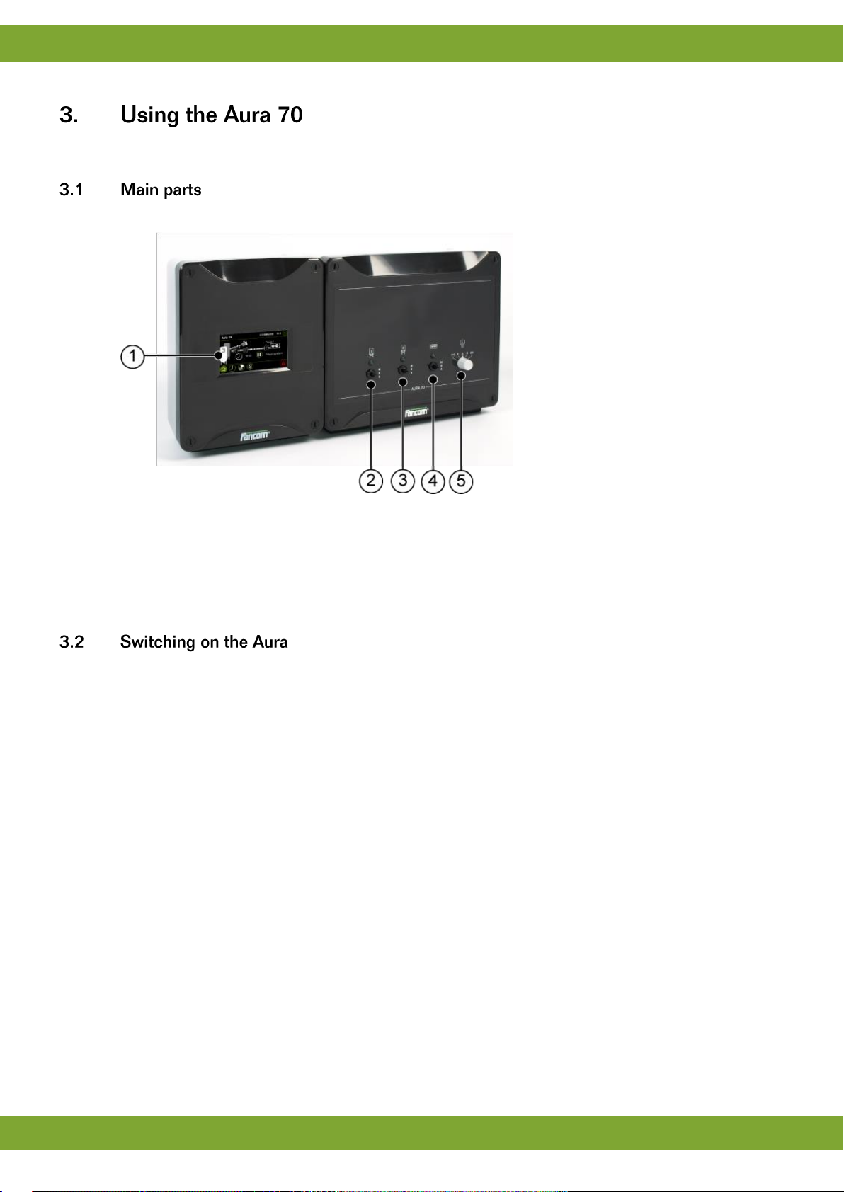
3.1 Main parts....................................................................................................................................... 6
3.2 Switching on the Aura..................................................................................................................... 6
3.3 Working with the Aura .................................................................................................................... 7
4. User settings............................................................................................................................................... 8
4.1 Overview......................................................................................................................................... 8
4.2 Feeding times................................................................................................................................. 8
4.3 Circuit times.................................................................................................................................... 9
4.4 Registration .................................................................................................................................... 9
5. Alarm ......................................................................................................................................................... 10
5.1 Alarm overview............................................................................................................................. 10
5.2 Alarm settings............................................................................................................................... 13
5.3 Alarm history................................................................................................................................. 13
6. Installing the Aura 70 ............................................................................................................................... 14
6.1 Determine location........................................................................................................................ 14
6.2 Mount the Aura 70........................................................................................................................ 14
6.3 Connect the Aura 70..................................................................................................................... 15
6.4 Connect the Aura 70 to FNet........................................................................................................ 16
7. Installer settings....................................................................................................................................... 17
7.1 CFG.............................................................................................................................................. 17
7.2 SYS .............................................................................................................................................. 18
7.3 INS ............................................................................................................................................... 19
8. Technical specifications Aura 70 + Switchbox ...................................................................................... 21
8.1 Interior control computer............................................................................................................... 22
8.2 Interior switch box......................................................................................................................... 22
8.3 Aura board.................................................................................................................................... 23
8.4 FCA Powerboard.......................................................................................................................... 23
8.5 Dosator motor / power supply....................................................................................................... 24
8.6 Silo switch / chain switch.............................................................................................................. 25
9. Appendix: EG-declaration of compliance............................................................................................... 26

Aura 70
General introduction
1
This manual has been created with the utmost care. If, however, you should discover an error, please inform
Fancom B.V.
This manual supplies information about connecting and configuring the control computer and information about
working with the control computer after installation. Always keep the manual close to the control computer.
The following symbols are used in this manual:
Tips and suggestions.
Note providing recommendations and additional information.
Warning indicating damage to the product if you do not follow procedures carefully.
Warning indicating danger to humans or animals.
Electrical shock hazard. Danger to humans and animals.
Example of a practical application of the described functionality.
Calculation example.
Describes the key combinations for arriving at a particular screen.
Decimals
The control computer and this manual use a decimal point in values. For example: a weight is shown as 1.5 kg
(not as 1,5 kg).
For any questions and support, please contact the local Fancom Sales & Service Center.

Aura 70
General introduction
2
Before installing and commissioning the Aura 70, read the safety instructions, provisions and conditions carefully.
This paragraph contains a number of general safety instructions. The installation of the device and remedying of
any malfunctions should be performed by a certified electrical installer according to the applicable norms. The
guarantee does not apply if this product is installed in any other way than is indicated by Fancom and if the
product's motor has been opened and changes have been made to the product.
Disconnect power before installation or before carrying out any maintenance to the control computer.
You must be able to switch off the device using a bipolar main switch.
Take precautions against electrostatic discharge (ESD) when working on the control computer. Ensure
the workplace is clean and dry.
Use the wiring/cables indicated on the connection diagrams and follow all. Only apply power after the
wiring has been connected correctly. Incorrect connections can cause permanent damage. Before a
new fuse is placed, the cause of the defect should be remedied by an authorized installer. Only replace
a defective fuse by a fuse of the same type (see connection diagram).
Inspect the control computer regularly for any damage. Report any damage to your installer
immediately. A damaged control computer is dangerous! Do not use running water (high pressure
cleaners) to clean your control computer. The control computer is water resistant, but not waterproof!
Do not switch off the computer when houses are unoccupied; otherwise there is the risk of
condensation in the computer.
The installation, of which this product is a part, must be equipped with a reliable, independent alarm
system, for example, a minimum/maximum thermostat. We advise you to test the alarm system every
day for proper functioning.
Connect each Fancom device according to the applicable legislation/regulations of the local energy
provider.
Check that the mains voltage and frequency, for which this computer is suitable, correspond to the
mains voltage and frequency on site.
Low-voltage and high-voltage wires may not be placed parallel to each other but may cross each other.
When using metal ducts, Fancom advises grounding the ducts at the ends and at as many other places
as possible.
Connect the computers to one group, from the main distributor.
Keep signal and power cables as short as possible.

Aura 70
Aura 70
3
The Aura 70 is a feed computer especially made for Fancom's EasyFeed feeding system. EasyFeed is a simple
dry feed system based on volume dosing at house level. All the animals are given the same type of feed, no feed
weighing takes place. The EasyFeed system is very flexible and offers the following possibilities:
1. Individual feeding of i.e. sows using dispensers.
2. Feeding of groups of rearers or fatteners using liquid and dry feed troughs is possible.
The Aura 70 has a built-in time clock. The feed system is started externally or automatically at preset times. The
Aura 70 enables to choose whether you will start:
Opening the dispensers: when the filling process starts, the dispensers will open and the feed will fall into
the troughs.
Filling the dispensers: when the filling process starts, the dispensers will be filled first.
The basic components of the feeding system usually include a silo auger and a feed chain drive unit. The
System full sensor on the end of the circuit registers if the system is full and stops filling it. A delay time for the
System full sensor can be set to ensure a successful start of the next feeding cycle, there will be still some feed
before the sensor. The silo augers remains off during this delay time to prevent the system from becoming
overfilled (till the silo switch sensor is free). The Return feed sensor turns on/off the feed intake from the silo
auger. If the Silo switch sensor detects no feed it will turn over to the second silo.
Figure 1: Schematic overview of an Aura 70 system

Aura 70
Aura 70
4
Figure 2: Schematic view for positioning the components
When the option ‘Filling the dispensers’ is chosen, the circuit will be filled first (circuit filling). This method is
usually used with dry or liquid feed troughs but there are also situations using a combination with dispensers. The
chain will start first to dose the feed into the dispensers. After a settable wait time the silo auger starts to filling
the circuit until the feed return sensor detects feed. During the settable wait time sections can be inspected and
dispensers can be adjusted per animal. After the wait time the dispensers will open and the feed will fall into the
troughs (Dispenser run time).
Figure 3: Example of a time schedule by ‘Filling the dispensers’

Aura 70
Aura 70
5
When the option ‘Start with dosator’ is chosen, the dispensers will open and the feed will fall into the troughs
(Dispenser run time). During the settable wait time sections can be inspected and dispensers can be adjusted
per animal. After the wait time the system starts the circuit filling process. The chain will start first to dose the feed
into the dispensers. After a settable wait time the silo auger starts to filling the circuit until the feed return sensor
detects feed.
Figure 4: Example of a time schedule by ‘Start with dosator’

Aura 70
Using the Aura 70
6
This chapter describes the main parts and the operation of the Aura 70.
The Aura 70 can be operated on the touch screen.
1. Touch screen
2. Silo 1 control switch
3. Silo 2 control switch
4. Circuit control switch (automatically switch off in case of a chain break)
5. Dosator control switch
The computer is automatically activated as soon as you switch on the power. The start-up progress is shown on
the screen.

Aura 70
Using the Aura 70
7
The Aura 70 screens are divided in three sections:
1. Title bar: Displays the date and time and provides access to the installation and user menu.
2. Working area: Displays the data user or installation settings of the control computer.
3. Menu selection and alarm bar: Provides buttons to navigate through available menus and an alarm
indicator to navigate to more details.
Only data important to you will appear on your control computer. This has been set in the installation
menus. This chapter explains all the management screens, which may include screens that are
irrelevant in your situation. Skip any sections not of importance to you.
The screen displays the status of a circuit. The circuit parts (sensors and chain) can be active or
inactive. Active parts are displayed green, inactive parts are grey.
The working area provides one action button: .

Aura 70
User settings
8
1. Silo Auger: If the silo auger is active the auger will light up green.
2. Silo’s: If more than one silo is used the silo number will appear in the icon.
3. Silo switch over sensor: If a silo is empty (sensor detects no feed) the system switch over to the other silo
(only if more than one silo is used).
4. Return feed sensor: If the return feed sensor detects feed it will stops the silo auger from filling the circuit.
5. System full sensor: If the chain is full the symbol light up green and the system will stops filling the
dispensers.
6. Clock: Readout of the current or next feeding time.
7. Start/Pause: Setting to start / pause ( ) the current feed time and readout of the current status (Filling
system, Wait dosator, Control dosator).
Readout of the starting times (maximum 24).
Setting of the starting times (hours:minutes).

Aura 70
User settings
9
Not available.
Readout of the circuit number.
Readout of the run time of today.
Readout of the run time of yesterday.
Readout of the run time of the day before yesterday.
Readout of the total run time.
To reset the values: tap a value, select Yes and tap

Aura 70
Alarm
10
The Aura 70 displays the alarm overview by pressing . There are two types of alarm:
1. Loud alarm: An active loud alarm sounds a siren, shows an alarm message and a report on the screen. This
type of alarm has a high priority.
2. Silent alarm: An active silent alarm shows an alarm message and a report on the screen. This type of alarm
has a low priority.
Status
Readout / setting the alarm status:
Alarm stand by: no alarm (stand by mode).
Alarm recovered: there was an alarm which has been recovered. The controller
switches off the alarm, but the alarm status remains visible.
Alarm disabled: switch off the alarm entirely. Only do this when houses are
unoccupied. Do not forget to reset the status to Alarm stand by.
Alarm temp. off: switch off the current alarm. When the alarm situation has been
cancelled, this status will automatically become Alarm stand by. Always check
that the status has reverted to Alarm stand by.
Silent alarm: alarm message shown on display only.
Alarm: the type of alarm is shown on the display.
Alarm test: test the alarm and after reset the status will be changed to Alarm
stand by.
Message
Readout of the alarms (see table below).

Aura 70
Alarm
11
Alarm messages
Proces alarms
Alarm
Action
Thermal alarm
Check the thermal security in the Aura 70.
Process blocked
System and new start time ranges are still blocked. Start the system (push button).
Chain is broken
No pulses or input cable break. Check the cable machine.
Maximum run time
Maximum running time reached. Check if any feed is being dispensed
unnecessarily, or if animal growth means that more feed is required. Adjust the
maximum running time setting.
System full sensor
The full report sensor does not report empty within the set time. Check the sensor
and adjust the delay setting if necessary.
Return feed sensor
Signal actual time not set. Check and adjust time, if necessary.
Power failure
Signal when starting up after Power Down from DoSA, PAUS, CirC / Fill. Solve the
problem and restart system.
Extern alarm 2+3
Check the connected components.
Dosator not closed
Check the dosator control close position.
System alarms
Alarm
Action
Backup alarm
The controller will be active on factory settings. Please check the settings.
Watchdog alarm
Communication alarm
Setting changed
Stack overflow
Double computer number
EPROM error
System error
Protected software
System alarms do not normally occur. Contact the installer immediately if these
system alarms are displayed.

Aura 70
Alarm
12
If the value responsible for causing the alarm comes within the alarm limits again, the situation is
considered recovered and the alarm is no longer active. The siren automatically disables and the alarm
status changes into Alarm recovered. This message remains visible so you can see what caused the
alarm. Press to change the alarm status into Alarm temp. off followed by Alarm stand by.
If an alarm occurs the LED strip and the ‘menu selection and alarm bar’ will flash red. Perform the following
actions in case of a:
1. Press . The alarm overview displays the alarm status Alarm and shows the alarm message.
2. Press once more. The siren will temporarily go off and the alarm status changes to Alarm temp. off. The
alarm message remains visible to investigate what caused the problem.
3. Solve the alarm situation. When the alarm situation is solved the alarm status changes into Alarm stand by.
1. Press . The alarm overview displays the alarm status Alarm and shows the alarm message.
2. Solve the alarm situation.
3. Press once more. The alarm message will disappear and the alarm status changes into Alarm temp. off
followed by Alarm stand by.
If the alarm is disabled the control computer will not generate any alarm messages (except system
alarms). Never switch the alarm off during regular operation.
The alarm can be fully disabled, e.g. when the house is empty. Disable the alarm as follows:
1. Press .
2. Change the alarm status to Alarm disabled. The control computer will give a warning to indicate that the
entire alarm system has been disabled and will flash red.
Reactivate the alarm by changing the alarm status to Alarm stand by. The alarm message states that the alarm
has been disabled and is active again. The message will be cleared from the alarm overview.
Fancom advises testing the alarm weekly for correct functioning. During the test the control computer
will give a loud alarm.
Test the alarm as follows:
1. Press .
2. Change the alarm status to Alarm test. The LED strip and the ‘menu selection and alarm bar’ will flash red
and the control computer prepares an alarm message. The Alarm overview displays the alarm message.
3. Clear the alarm by pressing . The alarm status changes into Alarm stand by.

Aura 70
Alarm
13
Max. runtime circuit
Setting of the maximum runtime (hours:minutes). One setting for all circuits.
The control computer stores the alarm history.
The computer stores the last six alarm messages.

Aura 70
Installing the Aura 70
14
1. Determine location
2. Mount the Aura 70
3. Connect the Aura 70
Takes into account the following guidelines:
Never place the Aura 70 in a place where the weather has direct influence (not in the sun, not in places
where the temperature can rise sharply etc.).
Never mount the Aura 70 near water pipes, drainage pipes etc.
Never mount the Aura 70 in a humid and/or dusty room and certainly not in the room where the animals
are present.
Mount the Aura 70 at such a height that you can control the Aura 70 easily (eye level) and square on a
solid backing. The swivels should be positioned at the bottom.
Mount the Aura 70 as follows:
1. Mark the screw holes by using the drilling template (taking into account the required edge distances).
2. Open the cover and fasten the control computer in the mounting holes on the corners.

Aura 70
Installing the Aura 70
15
Connect the Aura 70 as follows:
1. Open the cover.
2. Connect the Aura 70 to the manual switch.
3. Connect the manual switch to the main supply (be sure power is disconnected).
4. Connect other (signal wires) to the Aura 70, see chapter Technical specifications.
5. Close the cover.
Always use the cable swivels when connecting the Aura 70. Use the sealing discs supplied to seal off
any unused swivels. Use a sealant to seal all swivels, after the computer has been connected, to
prevent the entry of moisture, dust and/or aggressive gasses.
Check that the mains voltage and frequency, for which this computer is suitable, correspond to the
mains voltage and frequency on site.
Be sure that the Aura 70 is properly grounded. When using metal cable trays, grounding at one point of
the tray is recommended.
The Aura 70 should be possible to shut down with a double pole switch.
Connect the Aura 70 to a group from the main distributor and mount in separate cable trays.
Limit the length of the signal wires much as possible; avoid crossing high/low voltage wires.
To protect against lightning, place an over voltage protection device in the power supply of the Aura 70.
Condensation should never occur in the control computer.

Aura 70
Installing the Aura 70
16
Use of the terminal resistor depends on the location of the control computer in FNet. Control computers or end
stations at the beginning of the network require a terminal resistor. Depending on the device type a 120 Ohm
resistance, a jumper or a dipswitch is used to terminate the control computer.
Example: Setting the terminal resistor FNet
Four control computers connected using FNet.
Control computers 1 and 4 are at the end of the network. These control computers must be terminated.
Control computers 2 and 3 are looped. These looped control computers do not require a terminal
resistor.
The Fancom Greenlink cable (UTP 1x2x0.8mm, unshielded twisted pair) used to wire the FNET and I/O
net. Maximum cable length = 1200 meters.

Aura 70
Installer settings
17
Version
Readout of the software version number of the Aura 70.
Computer number
(FNET)
Setting of the unique computer number. If the computer is part of Fnet
communication, it must have its own, unique number (like all the other connected
computers).
To avoid peak load on the net by several computers activating
simultaneously, Fancom advises always entering a computer number.
Computer name
Setting of the name of the control computer.
Temperature unit
Setting of the unit of temperature (Celsius / Fahrenheit).
Language
Setting of the software language.
Reset to factory settings
Setting to restore the factory settings (YES / NO). Be carefull with this setting!
(Re)Calibrate screen
Setting to calibrate the touch screen (YES / NO). Tap on the dots to calibrate.
Be carefull with this setting!
Table of contents
Other Fancom Desktop manuals
Popular Desktop manuals by other brands

Aversix
Aversix AVM-3110 Series user manual

Dell
Dell OPTIPLEX 740 Quick reference guide

NEC
NEC PowerMate 2000 Series release note

HP
HP Xw4200 - Workstation - 1 GB RAM Service and technical reference guide

DT Research
DT Research 554 Basic operation guide

Rockwell Automation
Rockwell Automation 6181P user manual