Pro-face PL-5910 Series User manual

User Manual
PL-5910 Series
Panel Computer

1PL-5910 Series User Manual
Introduction
Thank you for purchasing Pro-face’s PL-5910 Series Panel Computer, hereafter
referred to as "the PL". This unit embodies Pro-face’s latest, cost-effective architecture
and is designed for Industrial Automation users.
Prior to using your PL, be sure to read this manual thoroughly to familiarize yourself with
the unit's operation procedures and functions.
1. It is forbidden to copy the contents of this manual in whole, or in part, without the
permission of the Digital Electronics Corporation.
2. The information in this manual is subject to change without notice.
3. This manual was written with care; however, if you should find any errors or omis-
sions, please contact Digital and inform them of your findings.
4. Please be aware that Digital Electronics Corporation shall not be held liable by the
user for any damages, related losses, or third party claims arising from the uses of
this product.
NOTICE:
Product names used in this manual are the trademarks of their respective manufacturers.
© 2004 Digital Electronics Corporation

Preface
2PL-5910 Series User Manual
This manual includes the following cautions concerning procedures that must be fol-
lowed to operate the PL-5910 Series unit correctly and safely. Prior to operating the
PL, be sure to read this manual and any related materials thoroughly to understand the
correct operation and functions of this unit.
Safety Icons
To allow you to use the PL correctly, throughout this manual, the following icons are
provided to indicate items requiring special attention.
These icons indicate the following levels of danger:
Indicates situations where severe bodily injury,
death or major equipment damage may occur.
Indicates situations where slight bodily injury or
machine damage can occur.
CAUTION
WARNING
Essential Safety Precautions
• To avoid the possibility of an electric shock, be sure to
connect the power cord to the PL before connecting it
to the main power supply.
• A fire or electrical shock may occur if voltages used with
the PL are beyond the specified range. Be sure to use
only the specified voltage.
• Before opening the PL unit’s rear maintenance cover, be
sure to turn the unit’s power OFF. This is because the
PL unit’s internal parts carry high voltages.
• To avoid fires or electrical hazards, do not modify the PL
in any way.
• Do not create touch panel switches that are used to either
control or to ensure the safety of equipment and person-
nel. Mechanical switches, such as an emergency stop
switch, a deadman (two-handed) start switch, etc., must be
installed and operated via a separate control system.
WARNING

Preface
3PL-5910 Series User Manual
•After the PL unit’s backlight burns out, unlike “Standby
Mode”, the PL unit’s touch panel is still active. If the
operator fails to notice that the backlight is burned out
and touches the panel, a potentially dangerous machine
operation error can occur.
If your PL unit's backlight suddenly turns OFF, use the
following steps to determine if the backlight is actually
burned out.
1) If your PL is not set to "Standby Mode" and the
screen has gone blank, your backlight is burned out.
2) Or, if your PL is set to Standby Mode, but touching
the screen does not cause the display to reappear,
your backlight is burned out.
• If metal particles, water or other types of liquids contact
any of the PL unit’s internal parts, immediately turn the unit’s
power OFF, unplug the power cord, and contact either your
PL distributor or the Digital Electronics Corporation.
• Read and understand Chapter 4 “Installation and Wir-
ing” thoroughly in order to select an appropriate instal-
lation location for the PL.
• Before either plugging in or unplugging a board or inter-
face connector, be sure to turn the PL unit’s power OFF.
• To prevent a possible explosion, do not install the PL in
areas containing flammable gases.
• Do not use the PL unit with aircraft control devices, aero-
space equipment, central trunk data transmission (com-
munication) devices, nuclear power control devices, or
medical life support equipment, due to their inherent re-
quirements of extremely high levels of safety and reli-
ability.
• When using the PL with transportation vehicles (trains,
cars and ships), disaster and crime prevention devices,
various types of safety equipment, non life-support-re-
lated medical devices, etc. be sure to design redundant
and/or fail-safe system designs to ensure the proper de-
gree of reliability and safety.
WARNING

Preface
4PL-5910 Series User Manual
CAUTION
• Do not strike the touch panel with a hard, heavy or
pointed object, or press on the touch panel with exces-
sive force, since it may damage the panel.
• Do not expose the PL to, or operate the PL in direct sun-
light, high temperatures and humidity, and in areas where
excessive dust and vibration will occur.
• Do not use the PL in areas where sudden, extreme changes in
temperature can occur. These changes may cause conden-
sation to form inside the unit, possibly causing an accident.
• To prevent the PL from overheating, be sure its air cir-
culation vents are clear and clean, and keep the unit’s
operation area well-ventilated.
• Do not operate or store the PL near chemicals, or where
chemicals can come in contact with the unit.
• To extend the lifetime of the PL unit's Hard Disk Drive
(HDD), use the BIOS, [POWER MANAGEMENT SETUP]-
[HDD Power Down] setting to stop the HDD motor when
the HDD is not being operated. The factory setting of
“5Min” is recommended.
With Windows®2000:
Use the [Control Panel] -> [Power Option] -> [Power Set-
ting] feature to turn the HDD off when not in use.
(Recommended setting: [After 5 mins]
When PL Hard Disk Drive (HDD) data is lost:
• The Digital Electronics Corporation cannot be held re-
sponsible or provide any compensation for damage(s)
caused by the loss of data stored in the PL unit’s hard
disk drive (HDD). It is therefore strongly suggested that
all important data and software be backed up regularly
to an external data backup device.
• Be aware that the Digital Electronics Corporation bears no
responsibility for any damages resulting from the
customer’s application of this unit’s hardware or software.
Preface
5PL-5910 Series User Manual
About the PL unit's Display Panel
• The PL unit's currently displayed data, its voltage and brightness setting each affect
the intensity of Contouring. (i.e., when some parts of the screen are brighter than
others, creating a wavelike pattern)
• There are minute grid-points (dark and light) on the Display Panel surface. This is part
of the PL unit's design and not a defect.
• Shadows may appear at the top of the LCD. This is normal for an LCD display.
• Sometimes the display area may look as if the display colors have changed.
This is a common attribute of LCD displays and is not a defect.
• Displaying a single image for long periods can cause an afterimage to remain when the
display is changed to another screen. To prevent this, periodically turn the PL OFF
and then ON again to remove this afterimage.
• Since the PL unit’s hard disk drive (HDD) is a consum-
able item, i.e. it has a finite lifetime, be sure to back up its
data regularly and prepare a spare HDD unit.
• To prevent file data damage, be sure to shut down the
PL unit’s OS before turning OFF the main power.
• After turning OFF the PL unit's power, be sure to wait
until the internal HDD stops spinning before turning the
power ON again (approx. 5 seconds).
• Do not turn PL unit's power OFF while the HDD is operating.
CAUTION

Preface
6PL-5910 Series User Manual
Table of Contents
Introduction................................................................................................................. 1
Essential Safety Precautions ..................................................................................... 2
Table of Contents ....................................................................................................... 6
DocumentationConventions .................................................................................... 10
PLSeries Panel Types.............................................................................................. 10
Package Contents......................................................................................................11
Special Features ....................................................................................................... 12
UL/c-UL/CSAApplicationNotes ............................................................................. 13
CE Marking Notes ................................................................................................... 13
Chapter 1 PL Basics
1.1 PLSetup ..................................................................................................... 1-1
1.2 PL System Design ..................................................................................... 1-2
1.2.1 ConnectingthePLUnit..................................................................1-3
1.3 Optional Items ........................................................................................... 1-4
Chapter 2 Specifications
2.1 General Specifications .............................................................................. 2-1
2.1.1 Electrical ........................................................................................2-1
2.1.2 Environmental ................................................................................2-2
2.1.3 Structural .......................................................................................2-3
2.2 FunctionalSpecifications........................................................................... 2-4
2.2.1 General ..........................................................................................2-4
2.2.2 Display ..........................................................................................2-4
2.2.3 ExpansionSlots..............................................................................2-5
2.2.4 Clock(RTC)Accuracy .................................................................. 2-5
2.3 Interface Specifications............................................................................. 2-6
2.3.1 Printer Interface (LPT1) ................................................................ 2-6
2.3.2 KeyboardInterface (KEY BOARD) .............................................. 2-6
2.3.3 MouseInterface(MOUSE)............................................................2-7
2.3.4 RS-232C Interface (COM1/COM2/COM3) ................................2-7
2.3.5 RAS Interface (RAS) ..................................................................2-8
2.4 PL Part Names and Features.................................................................. 2-11
2.5 External Dimensions ............................................................................... 2-13
2.5.1 PL-5910T ...................................................................................2-13
2.5.2 PL-5910T withInstallationFasteners........................................... 2-14
2.5.3 PL-5910Twith FDD Unit ............................................................ 2-15

Preface
7PL-5910 Series User Manual
2.5.4 PL-5910TwithPL-RC500 Conversion Unit ................................2-17
2.5.5 PL-5911T....................................................................................2-18
2.5.6 PL-5911TwithInstallationFasteners ............................................2-19
2.5.7 PL-5911Twith FDD Unit ............................................................ 2-20
2.5.8 PL-5911TwithPL-RC500 Conversion Unit................................. 2-22
2.5.9 InstallationFasteners ....................................................................2-23
2.5.10 PanelCutDimensions...................................................................2-23
Chapter 3 Installing Optional Units and Expansion Boards
3.1 Installation ................................................................................................ 3- 1
3.1.1 RemovingtheRearMaintenanceCover .........................................3- 2
3.1.2 InstallingtheDIMModule(PL-EM128/PL-EM256) .....................3- 3
3.1.3 InstallingtheFDDUnit(PL-FD500)..............................................3- 4
3.1.4 InstallingtheFDDUnit(PL-FD510)..............................................3- 7
3.1.5 Removing/InstallingtheHDDUnit(PL-HD220)............................3- 9
3.1.6 InstallinganExpansionBoard ...................................................... 3- 10
3.1.7 Connectingthe CD-ROM Drive Unit (PL-DK200) ..................... 3- 11
Chapter 4 Installation and Wiring
4.1 InstallationCautions ................................................................................ 4- 1
4.2 Installing thePL ....................................................................................... 4- 3
4.2.1 InstallationProcedures .................................................................. 4- 3
4.3 WiringthePL............................................................................................ 4- 8
4.3.1 Connecting the Power Cord ..........................................................4- 8
4.3.2 PowerSupplyCautions ............................................................... 4- 11
4.3.3 GroundingCautions.....................................................................4- 12
4.3.4 CautionsWhenConnectingI/OSignalLines ................................4- 12
Chapter 5 System Setup
5.1 SetupProcedures...................................................................................... 5- 1
5.2 System Parameters .................................................................................. 5- 3
5.2.1 Standard CMOS Features ............................................................5- 3
5.2.2 IDEHDDAuto-Detection .............................................................5- 5
5.2.3 Advanced BIOS Features .............................................................5- 6
5.2.4 AdvancedChiPLetFeatures..........................................................5- 9
5.2.5 IntegratedPeripherals.................................................................. 5- 11
5.2.6 PowerManagement Setup ..........................................................5- 14
5.2.7 PnP/PCIConfigurations ..............................................................5- 16
5.2.8 IRQ Resources ...........................................................................5- 18
5.2.9 DMAResources ......................................................................... 5- 19
5.2.10 Frequency/VoltageControl ..........................................................5- 20

Preface
8PL-5910 Series User Manual
5.2.12 LoadOptimizedDefaults .............................................................5- 21
5.2.13 Set Supervisor Password ............................................................ 5- 21
5.2.14 Set User Password .....................................................................5- 21
5.2.11 LoadFail-SafeDefaults............................................................... 5- 21
5.2.15 Save & Exit Setup.......................................................................5- 22
5.2.16 ExitWithoutSaving .....................................................................5- 22
Chapter 6 OS Setup
6.1 CD-ROM Contents................................................................................... 6-1
6.1.1 Tree-DiagramList ..........................................................................6-1
6.2 SettingUpYourPLOS .............................................................................. 6-2
Chapter 7 Using Windows
7.1 Installation Methods ................................................................................. 7-1
7.1.1 InstallationProcedures ................................................................... 7-1
7.1.2 HardDiskContents .......................................................................7-2
7.2 Installing Drivers....................................................................................... 7-3
7.2.1 InstallingtheChipsetDriver ............................................................ 7-3
7.2.2 InstallingtheGraphicAcceleratorDriver ......................................... 7-3
7.2.3 InstallingtheLANDriver............................................................... 7-4
7.2.4 InstallingtheMouseEmulator ........................................................7-5
7.3 Windows®UtilityPrograms...................................................................... 7-6
7.3.1 API-DLL.......................................................................................7-6
7.3.2 BacklightOFF Screen Saver (Backlight control.scr) ...................... 7-6
7.3.3 ScreenDisplayON/OFFUtility(Disp.exe) ..................................... 7-7
7.3.4 KeyboardEmulator(Keyclick.exe) ................................................ 7-7
7.3.5 SystemMonitor/RASApplication(Pl_smon.exe/Pl_wps.exe).......... 7-7
7.3.6 FunctionKeyUtility(Fnckey32.exe) ..............................................7-8
7.4 Windows NT® 4.0 / Windows ®2000 Settings......................................... 7-9
7.4.1 AutomaticSystemLog-OnSetup ................................................... 7-9
7.4.2 UsinganUninterruptedPowerSupply ..........................................7-10
7.4.3 WhenChangingtheSystemDesign ............................................... 7-10
7.4.4 Changingto theNTFSFile System ............................................... 7-11
Chapter 8 Using MS-DOS
8.1 MS-DOS® Utility Programs ..................................................................... 8-1
8.1.1 TouchPanelHandler(Atph59.exe) ................................................. 8-1
8.1.2 TouchPanelDataCalibration(CALIB59.EXE) ............................. 8-18
8.1.3 ScreenDisplayON/OFFUtility(Disp.exe) ................................... 8-20
8.1.4 SerialPortDriver(EXTCOM.SYS) .............................................8-21

Preface
9PL-5910 Series User Manual
8.1.5 BacklightBurnoutDetectionProgram(BLSET.EXE) .................... 8-28
8.1.6 BacklightControl Program(INT5F.COM) ...................................8-28
8.1.7 LANDriver .................................................................................8-28
8.2 SerialCommunication ............................................................................. 8-29
8.3 BIOS List................................................................................................. 8-30
Chapter 9 System Monitoring
9.1 RAS Feature.............................................................................................. 9-1
9.1.1 Usingthe RASFeature................................................................... 9-1
9.1.2 RASFeatureDetails ......................................................................9-2
9.1.3 RASFeature Overview ..................................................................9-6
9.2 System Monitor......................................................................................... 9-7
9.2.1 Setup .............................................................................................9-7
9.2.2 SystemMonitor PropertySettings(PL_Wps.exe) ........................... 9-8
9.2.3 SystemMonitorOperation(PL-Smon.exe)................................... 9-10
9.2.4 ErrorMessages............................................................................9-12
9.2.5 ErrorDisplaysWhenUsingEventViewer .....................................9-13
9.3 Remote RAS............................................................................................ 9-15
9.3.1 SystemDesign .............................................................................9-15
9.3.2 InstallationProcedures ................................................................. 9-15
9.3.3 Usingthe RASFeature................................................................. 9-16
9.3.4 SystemMonitor/RAS FeatureRead/Write ................................... 9-17
9.3.5 Restrictions .................................................................................9-20
9.4 RemoteShutdown Feature...................................................................... 9-21
Chapter 10 Maintenance and Inspection
10.1 RegularCleaning..................................................................................... 10-1
10.1.1 CleaningtheDisplay ..................................................................... 10-1
10.2 Usage Lifetimes....................................................................................... 10-2
10.3 Part Replacement .................................................................................... 10-2
10.3.1 ReplacingtheInstallationGasket...................................................10-2
10.3.2 ReplacingtheBacklight ................................................................10-3
10.4 Troubleshooting ....................................................................................... 10-7
10.5 Periodic Maintenance Points ................................................................ 10-10
Appendices
A.1 HardwareConfiguration....................................................................... App-1
A.1.1 I/O Map ................................................................................... App-1
A.1.2 MemoryMap ........................................................................... App-2
A.1.3 InterruptMap ........................................................................... App-3
A.2 ConsentAgreement.............................................................................. App-4
Preface
10 PL-5910 Series User Manual
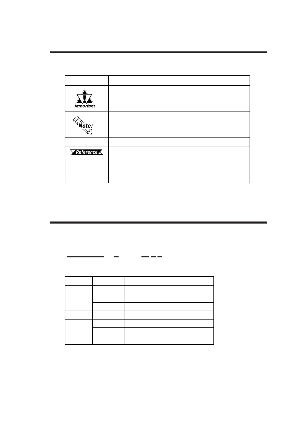
Symbol Meaning
Indicatesimportantinformationorproceduresthatmustbe
followedforcorrectandrisk-freesoftware/deviceoperation.
Providesuseful orimportantsupplemental information.
*1 Indicatesuseful orimportantsupplementalinformation.
Refersto usefulorimportantsupplementalinformation
1) , 2) Indicatesstepsina procedure.Besuretoperform thesestepsin
theordergiven.
PL Abbreviationforthe PL-5910 SeriesofIndustrialComputers.
Documentation Conventions
The list below describes the documentation conventions used in this manual.
PL591 *- T**
ABCDE
DC24V Series Unit Model Numbers:
PL Series Panel Types
Item Code Meaning
APL591 PL-5910SeriesUnit
03-slottype
11-slottype
CTTFTColorLCDdisplay
1AC100VModel(nocertification)
4CEMarking,UL/c-UL(CSA)Approval
E*RevisionNo.
B
D
Preface
11PL-5910 Series User Manual
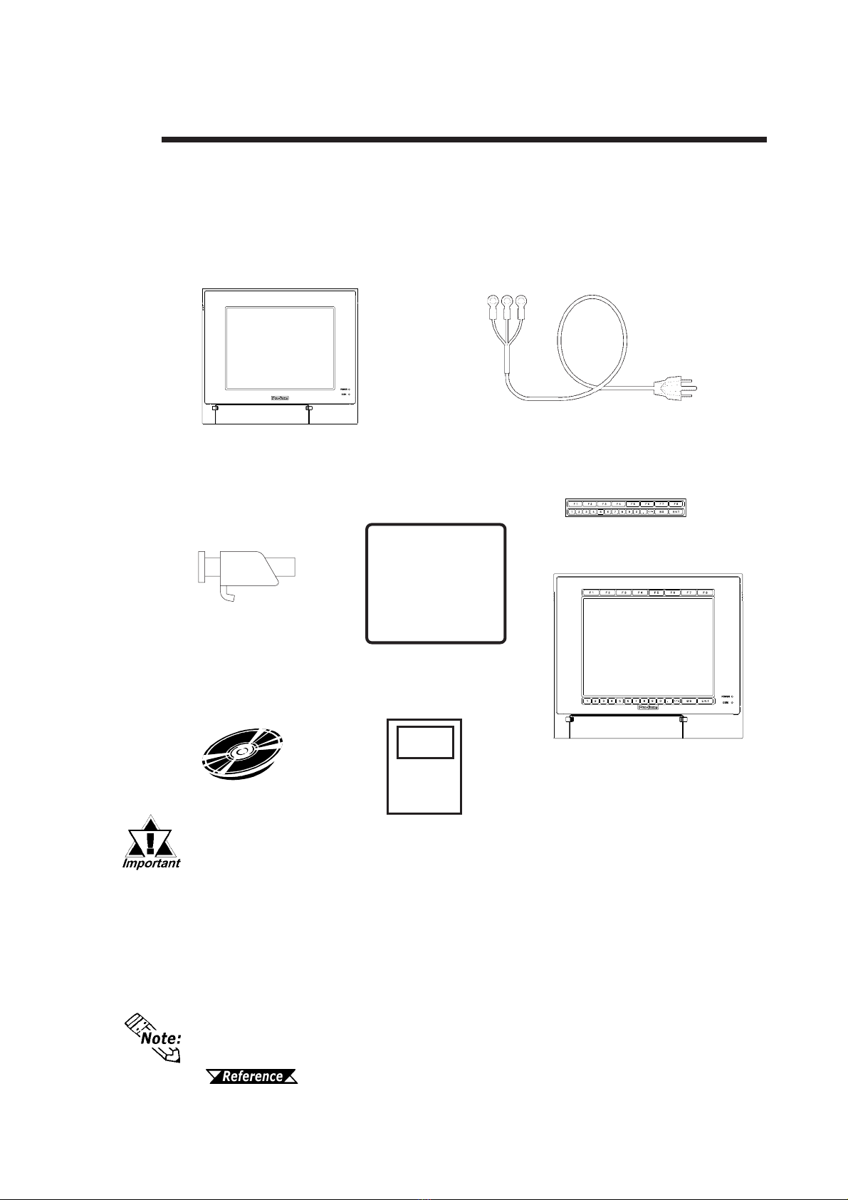
The PL unit's packing box contains the items listed below. Please check to confirm that
all items shown below have been included.
Package Contents
- Be careful when handling the PL not to damage the built-in HDD
- This power cord is designed only for AC100V/AC115V use. Any other
voltage will require a different power cord.
- If your PL unit contains a built-in optional item, that item's Installation
Guide will also be included in the PL unit’s packing box. Be sure to
check that all items normally included with that item are also included
in this box.
Power Cord
(included only with PL-5910-T11/PL5911-T11)
PL Unit
PL-5910T/PL-5911T
Installation
Fasteners
(4 brackets/set)
Installation
Gasket
Function Labels
Attach the function labels as
shown below.
PL-5910 Series User
Manual & Driver CD
The CD-ROM contains the PDF version of the User Manual, API Reference Manual
and all PL-5910 Series Utility and Driver files.
Chapter 6 - Setting Up Your PL OS
Installation
Guide

Preface
12 PL-5910 Series User Manual
Special Features
The PL-5910 Series displays are equipped with the following features:
The Latest, High-Performance Architecture
Designed around the ULV Celeron® 650MHz CPU, the PL utilizes the type of high-
performance architecture that offers you superior compatibility.
Bright 10.4" LCD with a Wide Viewing Angle
The PL unit’s large 10.4-inch 640 x 480 TFT LCD display offers excellent visibility
and brightness.
This top-of-the-line TFT color LCD allows you to create detailed and impressive
260,000-color images, with superb brightness and a wide viewing angle.
Easy Front Panel Installation
The PL is designed to be installed easily into the front of any panel or device. It is
also rugged enough for use in harsh, industrial environments, such as those found in
the factory automation industry and its front panel boasts an IP65f-equivalent rating.
High Resolution, Analog Type Resistive Film Touch Panel
Standard equipment with the PL is a high resolution 1024 x 1024 touch panel. Also,
the separately sold mouse emulation utility provides mouse-like functionality and
pointer control.
Highly Expandable
Two types of PL units are available: a 1-slot type (with 1 PCI bus), and a 3-slot type
(with 2 PCI buses). These slots can accommodate both Digital’s own optional
boards as well as other commercially available expansion boards.
Digital also offers a wide variety of optional products, such as FDD units, DIM
modules and others.

Preface
13PL-5910 Series User Manual
UL/c-UL/CSA Application Notes
CE Marking Notes
The PL5910-T41-24V/PL5911-T41-24V Series units are UL/c-UL/CSA 60950
recognized products. (UL File No. E171486). Please pay special attention to the
following instructions when applying for UL/c-UL/CSA approval for machinery which
includes any of these PL units.
Equipment with a PL mounted in it requires UL evaluation for the combination of the PL
and the equipment.
The PL conforms as a component to the following standards:
UL 60950-1
Third Edition, dated December 1st, 2001 (Standard for Safety of Information Technol-
ogyEquipment)
CAN/CSA-C22.2 No. 60950-1-03
Third Edition, dated December 1st, 2001 (Standard for Safety of Information Tech-
nologyEquipment)
PL5910-T41-24V (UL Registration Model: 3382701-01)
PL5911-T41-24V (UL Registration Model: 3382701-02)
When the PL unit is a built-in component of another product:
• The rear face of the PL unit is not an approved enclosure. When building the PL into
another product, that product should be designed so as to meet standards for an
approved enclosure.
• Use the PL indoors only.
• When using natural air ventillation, be sure to install the PL unit in a vertical panel.
Also, be sure to create at least 50mm of air space around the rear face of the PL
unit. If this amount of space is not created, the PL unit's internal temperature will
increase and may lead to the unit's failing to meet UL standards.
•When connecting the PL unit’s power cord, be sure to use a cord that is appropriate for
the current and voltage used, and that has conductive wires that are 0.75 mm2or larger.
•When an end-use product will include the PL, be sure to design the PL unit’s power
cutoff switch as a separate disconnect device and locate it where the operator can
easily reach it.
•Danger of explosion if backup battery is incorrectly replaced. Replaced only with
same or equivalent type recommended by the manufacturer. Dispose of used batter-
ies according to the manufacturer’s instructions.
The PL5910-T41-24V/PL5911-T41-24V Series units are CE marked products that
conform to EMC directives EN55011 (Group 1 Class A) and EN61000-6-2.

Preface
14 PL-5910 Series User Manual
Memo

1-1PL-5910 Series User Manual
Chapter
1 PL Basics
1. PL Setup
2. PL System Design
3. Optional Items
1.1 PL Setup
• After completing the hardware setup and before any data or applica-
tions can be installed on the hard disk drive, the OS (Windows®or MS-
DOS®) must be used to initialize the HDD and create partitions. For
details concerning these procedures, refer to the OS maker’s installa-
tion manual.
• After turning the PL OFF, be sure to wait at least 5 seconds before
turning ON again. If the unit is stated within 5 seconds, it may not start
upcorrectly.
• The PL is designed for use with MS-DOS®, WindowsNT®4.0, and Win-
dows®2000. Other operating systems are not supported by this PL
unit's driver software.
Usethefollowingstepstoset up your PL unit.
4.3 Wiring the PL
Chapter 5 System Setup
OS manufacturer’s installation manual
When using Windows, see 7.1 Driver
Installation
When using MS-DOS, see 8.1 Driver
Installation
Install the required applications. Please refer to
each application's installation manual for setup
instructions.
Install the OS
Copy all Drivers and
Utility Programs
Install Individual
Drivers
Setup System
Install Applications
Install PL unit
Turn PL ON
Install Hard Disk
1-2 PL-5910 Series User Manual
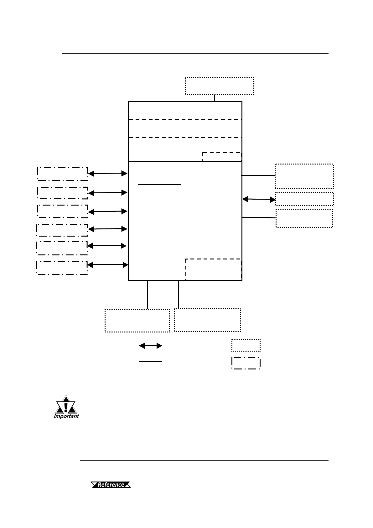
1.2 PL System Design
The above system configuration illustrates the PL unit's internal de-
sign and range of connectable peripherals. The user's actual configu-
ration may differ.
Exp. DIM Module
memory
(
128MB/256MB
)
Screen Protection Sheet
Keyboard
Mouse
Peripheral Dev.
Printer
Touch Panel
Display Unit (TFT Color)
Display Module
Reset Button
Main Module
Expansion slots:
- PL-5910T:2 PCI/ISAslots and 1ISA
(Using 2PCI slots reduces ISA slots to1)
- PL-5911T:1 ISAand 1 PCIslot
(Using1 PCI slotreduces ISA slots to0)
Pow er Unit
DCIN(19.2 to 28.8V)
HDD/CFCard Unit
Expansion Slot*1
HDD/CFCard Unit
Expansion Slot*1
Optional Items
Commercial Items
(Purchased byUser)
PL Unit
RS-232C
3 ports
LPT
1 Port
IDE IDE
Cable Connection
A
ttached to Main Uni
t
CD-ROMDrive Unit*1
Onlyto PL-5910T
10BASE-T
100BASE-TX
USB Type Units
LAN Network
FrontMountFDD
Unit
USB
2 Ports
PS/2
1 port
PS/2
2 ports 2 Slots
*1 Certain limitations exist for the combinations of the HDD Unit, the CF Card unit,
and the CD-ROM drive.
1.3 Optional Items

1-3PL-5910 Series User Manual
1.2.1 Connecting the PL Unit
The PL unit's touch panel can connected via a serial (COM4) interface or a USB
interface.ThePLunit'sfactorysettingisforusingaserialinterface.Ifyouhaveinstalled
Windows®2000 in your PLunit and you wish to change this setting to a USB interface,
pleasefollowthesteps givenbelow.
MS-DOS®and WindowsNT®4.0 operating systems are not compatible with USB
interfaces.
Touch Panel I/F Selector Switch
Set the touch panel selector switch to "U". For details,
2.4 PL Part Names and Features
Be sure to change the touch panel selector switch only after turning the
PL unit OFF. If the PL unit is running when this is performed, it can cause
the unit to malfunction.

1-4 PL-5910 Series User Manual
Maintenance Options
Name Model Number Description
Installation
Fasteners CA3-ATFALL-01 Usedtoinstall thePLintoapanelorcabinet.Same as
originalequipmentbrackets.(4brackets/set)
Installation
Gasket PL-WS500 Used to prevent moisture from entering into the PL
unit’s case from the frontface. Same as original
equipmentgasket.
Backlight GP577T-BL00-MS SpareBacklightformaintenance.(2bulbs/set)
Options
1.3 Optional Items
Name Model Number Description
PL-EM256 256MBofSDRAM (DIMM)memory
PL-EM128 128MBofSDRAM (DIMM)memory
FDD Unit PL-FD510 PC/AT compatible3.5”FDDunit
(Attachestofrontslot)
CD-ROM Unit PL-DK200 IDE(ATAPI)compatible CD-ROM drive unit
–fordevelopmentand maintenanceuse.
(ConnectioncableisincludedwithCD-ROM unit)
CF Card Unit PL-CF200 Designed exclusivelyfor5Vtypecards.
CA3-CFCALL/128MB-01 Type 1CF card(128MB)
CA3-CFCALL/256MB-01 Type 1CF card(256MB)
CA3-CFCALL/512MB-01 Type 1CF card(512MB)
CA6-CFCALL/1GB-01 Type 1 CF card (1GB)
HDD Unit PL-HD220 20GB2.5"HDD Unit(OSnotincluded)
RS-232C/RS-485
Adaptor PL-RC500 ConvertsanRS-232CinterfacetoanRS-485
interface. ConnectstoCOM3.
Screen Protection
Sheet PL-CS001 Disposable,dirt-resistantsheetforscreenprotection.
Touch Panelcan beusedthroughthissheet.
(10sheets/set)
Glare Resistant
Sheet PL-NGS01 Disposable,glare-resistantsheetfor screen
protection.TouchPanel canbe usedthroughthis
sheet. (5 sheets/set)
DIM Module
CF Card

Chapter 1 - PL Basics
1-5
PL-5910 Series User Manual
MS: Combination of 2 units - Master or Slave, is possible.
M: Used only for Master.
S: Used only for Slave.
• Since the PL unit's hard disk drive (HDD) is a consumable item, i.e. it
has a finite usage lifetime, be sure to back up its data frequently and
perform regular maintenance.
• The Hard Disk lifetime given here may be reduced due to unforeseen
environmental factors, however, generally speaking, at an operating
temperature of 20oC and assuming 333 hours of operation (HDD mo-
tor is ON) per month (an access time of 20% or less), the HDD unit
should last for 20,000 hours (power is ON) or approximately 5 years,
whichever comes first.
• The PL is equipped with three IDE interfaces. Two can be used by the HDD or
FFD units (PL-5911T can use only one), and one can be used by either the CD-
ROM drive or the Mirror Disk unit. Physically, even though up to three IDE
drive units can be connected at the same time, IDE interface specifications
require that a controller's simultaneous operation be limited to a single master
and slave unit, for a total of two devices. The following chart shows the combi-
nations available when using two IDE units (PL-5911T can use only one).
Commercially Available Items
PL-5910Seriesunitscan allusecommerciallyavailableexpansion boards(PCI/ISA
compatible) as well as a standard keyboard, mouse, printer, and USB-compatible
devices. However,amongthecommerciallyavailable USBdevices,notallwillbe
compatiblewiththePLunit.
• Be sure to use only DIM modules manufactured by Digital. Installing other
DIM modules may result in either damage to or failure of the PL, and will void
your warranty.
• When using USB type devices, be sure they are USB compatible, and be sure to
read that device's Installation Guide prior to connecting it to the PL.
MSMMMMS S S
CD-ROM Drive Unit S S S S
CF Card Unit S S S M M M M MS
Table of contents
Other Pro-face Desktop manuals


