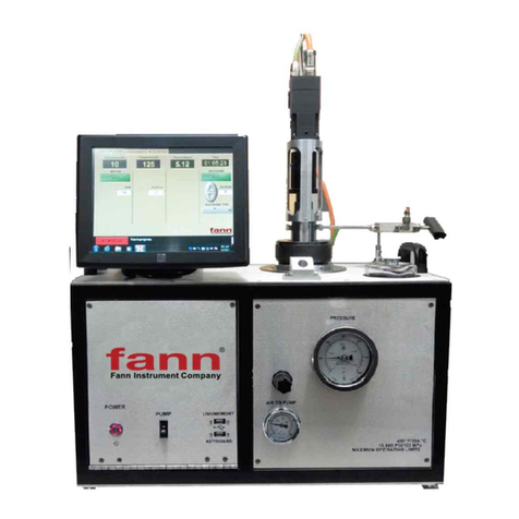
fann 640 User manual

©2016 Fann Instrument Company
HTHP Consistometer Model 640 & 640CC
Instruction Manual
Manual No. D01206676 Revision A
Instrument No. 102538936 (Model 640)
102546634 (Model 640CC)

Model 640 & 640CC Instruction Manual
D01206676 Revision A February 2016 2
HTHP Consistometer, Single & Dual Cell Instruction Manual
©2016 Fann Instrument Company
Houston, Texas, USA
All rights reserved. No part of this work covered by the copyright hereon may be reproduced or
copied in any form or by any means (graphic, electronic, or mechanical) without first receiving the
written permission of Fann Instrument Company, Houston, Texas, USA.
Printed in USA.
The information contained in this document includes concepts, methods, and apparatus which may be
covered by U.S. Patents. Fann Instrument Company reserves the right to make improvements in
design, construction, and appearance of our products without prior notice.
FANN®and the FANN logo are registered trademarks of Fann Instrument Company in the United
States and/or other countries. All other trademarks mentioned in the operating instructions are the
exclusive property of the respective manufacturers.
Contact Fann Instrument Company
Phone
1-281-871-4482
1-800-347-0450
Fax
1-281-871-4358
Postal Address
Fann Instrument Company
P.O. Box 4350
Houston, Texas, 77210 USA
Shipping Address
Fann Instrument Company
14851 Milner Road, Gate 5
Houston, Texas, 77032, USA
Online
www.fann.com

Model 640 & 640CC Instruction Manual
D01206676 Revision A February 2016 3
Table of Contents
1 Introduction ..............................................................................................................6
1.1 Document Conventions....................................................................................7
2 Safety.......................................................................................................................8
2.1 Safe Pressurization ............................................................................................8
2.2 Safe Heating ......................................................................................................8
2.3 Safe Electrical Operation....................................................................................8
3 Instrument Overview ................................................................................................9
4 Specifications.........................................................................................................10
5 Installation..............................................................................................................11
6 Touchscreen Software ...........................................................................................14
6.1 Using the Touchscreen ..................................................................................14
6.2 View Test.......................................................................................................14
6.3 Instrument Setup............................................................................................15
6.4 Calibrate Temperature/Calibrate Pressure.....................................................15
6.5 Sample Rate ..................................................................................................15
6.6 Units...............................................................................................................16
6.7 Archive Data ..................................................................................................16
6.8 Edit Instrument...............................................................................................16
7 Test Setup..............................................................................................................17
7.1 Temperature Control (Pressure When Available) ...........................................17
7.2 Hesitation Squeeze........................................................................................18
7.3 Optional Parameters and Profile Saving.........................................................19
8 Start Test ...............................................................................................................20
8.1 Live Testing Screen........................................................................................20
9 Stopping a Test......................................................................................................21
9.1 Software Upgrades ........................................................................................21
9.2 Using the USB Memory and Printer................................................................21
10 Front Panel Controls ..............................................................................................22
10.1 Hydraulic Pressure Controls...........................................................................22
10.2 Pneumatic Controls........................................................................................23
10.3 Cooling Water Controls..................................................................................24
10.4 Other Electrical and Electronic Controls.........................................................24
11 Operation and Calibration.......................................................................................26
11.1 Running a Thickening Time Test....................................................................26

Model 640 & 640CC Instruction Manual
D01206676 Revision A February 2016 4
11.2 Stopping a Thickening Time Test...................................................................27
11.3 Calibration......................................................................................................27
11.4 Pressure Calibration Procedure .....................................................................28
11.5 Consistency Calibration Procedure ................................................................29
12 Maintenance and Servicing....................................................................................31
12.1 Pressure Valve and Hydraulic System Maintenance ......................................31
12.2 Potentiometer Mechanism (Pot Mech) Maintenance ......................................32
12.3 Slurry Cup Maintenance.................................................................................32
12.4 Changing the Metal O-ring on the Cylinder Assembly ....................................33
12.5 Changing/Cleaning the High Pressure Filter Element.....................................33
12.6 Replacing the Low Pressure Filter Element....................................................34
12.7 Potentiometer Mechanism Resistor Replacement..........................................34
12.8 Potentiometer Mechanism Spring Replacement.............................................35
12.9 Servicing the Inner Magnetic Drive Shaft........................................................36
12.10 Servicing the Outer Magnetic Drive Rotator...............................................36
12.11 Removal of the Magnetic Drive Housing....................................................37
12.12 Heater Replacement..................................................................................38
13 Troubleshooting .....................................................................................................40
14 Warranty and Returns............................................................................................44
14.1 Warranty ........................................................................................................44
14.2 Returns ..........................................................................................................44

Model 640 & 640CC Instruction Manual
D01206676 Revision A February 2016 5
List of Tables
Table 4-1 Model 640 & 640 CC Specifications..............................................................10
Table 11-1 Consistency as a Function of Weight vs Torque*........................................30
Table 13-1 Troubleshooting Model 640 & 640 CC ........................................................40

Model 640 & 640CC Instruction Manual
D01206676 Revision A February 2016 6
1 Introduction
Cements are a critical element in the drilling, completion, workover, and
abandonment of wells. For each application, cement slurry is designed with specific
properties and is given additives that provide predictable slurry density, volume,
viscosity, compressive strength, fluid loss, gas migration, and thickening time.
Slurry thickening time, or the time a slurry remains pumpable in a well, is one of
the most critical properties in designing cement slurry. A predictable thickening
time is desired, while maintaining the other specific properties of the cement slurry.
The thickening time can be measured in a laboratory by testing a sample of the
cement slurry in a pressurized consistometer. The elapsed time between initial
application of pressure and temperature on the slurry sample and occurrence of a
predetermined value of consistency (usually 100 Bearden Units, Bc) is the
thickening time for the sample at the particular specification test schedule. The
typical test schedules are listed in API Specification 10 on oilwell cements.
The Model 640 & 640CC Pressurized Consistometers are able to test cement
slurries at temperatures up to 600 F/316 C and pressures as high as 40,000 psig/276
MPa.

Model 640 & 640CC Instruction Manual
D01206676 Revision A February 2016 7
Document Conventions1.1
The following icons are used as necessary in this instruction manual.
NOTE.Notes emphasize additional information that may be
useful to the reader.
CAUTION. Describes a situation or practice that requires operator
awareness or action in order to avoid undesirable consequences.
MANDATORY ACTION. Gives directions that, if not observed,
could result in loss of data or in damage to equipment.
WARNING! Describes an unsafe condition or practice that if not
corrected, could result in personal injury or threat to health.
ELECTRICITY WARNING! Alerts the operator that there is risk of
electric shock.
HOT SURFACE! Alerts the operator that there is a hot surface and
that there is risk of getting burned if the surface is touched.
EXPLOSION RISK! Alerts the operator that there is risk of
explosion.

Model 640 & 640CC Instruction Manual
D01206676 Revision A February 2016 8
2 Safety
Safe laboratory practices and procedures should be observed while operating and
maintaining the Model 640 & 640 CC. Follow the instructions provided to avoid
personal injuries or damage to the equipment.
Always wear appropriate personal protective equipment (PPE) when operating or
maintaining the Consistometer.
Safe Pressurization2.1
This Consistometer has pressurized air, water, and hydraulic lines that present a
hazard if not depressurized before maintenance or disassembly.
The hydraulic diaphragm pump and the pressure relief valve require compressed
air. Before working on any of these devices or connected air lines, shut off the
compressed air supply to the machine, and carefully relieve air pressure from the
machine.
Safe Heating2.2
Before opening the pressure chamber, use the cooling system to lower the
temperature to at least 120°F (49°C). The machine uses domestic water as coolant.
Shut off the domestic water supply before servicing.
NEVER operate the heater on an empty chamber. The heater element will quickly
overheat and fail. To prevent smoke and possible fire, always fill the chamber and
pressurize before heating.
Safe Electrical Operation2.3
Disconnect the power cable before attempting any electrical or mechanical
maintenance. Be aware that after the power switch is turned off, the electrical
terminals inside the panel will remain electrically energized.
Refer to the electrical schematic before performing any maintenance or
troubleshooting.
Always disconnect the power cable before attempting any repair.

Model 640 & 640CC Instruction Manual
D01206676 Revision A February 2016 9
3 Instrument Overview
The consistometer Slurry Cup Assembly uses a rotating, cylindrical slurry cup and
a stationary paddle assembly enclosed in a pressure vessel. Pressure is applied to
the vessel using mineral oil and an air driven hydraulic pump. A tubular heater
surrounding the slurry cup supplies heat to the pressure chamber. A centerline
thermocouple is provided for determining the temperature of the cement slurry. The
slurry cup is rotated through the use of an electric motor and a magnetic drive unit.
The rotational speed of the slurry cup is variable between 25 and 250 rpm to allow
the user to study slurries at speeds other than the API prescribed speed of 150 rpm.
The consistency of the cement slurry is measured through a potentiometer
mechanism commonly referred to as a “pot mech”. The potentiometer is coupled
with a torsion spring to resist the rotating force of the paddle. The rotational force
is proportional to the consistency of the cement slurry and is measured through the
potentiometer resistor as the spring deflects under load. The consistency is
displayed on the plot generated by the data acquisition system. The consistency
values are recorded in Bearden Units of consistency (Bc). Bearden units are defined
in API Specification 10. The consistometer is equipped with one or two devices for
post-test cooling of the instrument. The first is an external-cooling coil attached to
the pressure vessel. After completion of the test, cooling water may be circulated
through this coil to cool the pressure vessel. The instrument is optionally equipped
with an oil reservoir cooling coil as well.
These pressurized consistometers are equipped with a state-of-the-art temperature
controller and data acquisition system that provides unparalleled ease of use for the
operator. The parameters of interest may be displayed in either English or SI units.
Temperature control and data acquisition is programmed through the use of a touch
screen monitor. A separate PC and keyboard/mouse are not required but may be
connected through a network cable. A plot showing temperature and consistency
(pressure is optional) may be plotted on any compatible ink jet printer. The plots
may also be transferred automatically to a network or USB drive for use on a user
supplied computer.

Model 640 & 640CC Instruction Manual
D01206676 Revision A February 2016 10
4 Specifications
Table 4-1 Model 640 & 640 CC Specifications
Category Specification
Electrical
Input Voltage 230 VAC (±10%)
Input Power 5500W (single), 11000W (dual)
Current 24A (single), 48A (dual)
Input Frequency 50-60Hz
Mechanical
Height 70in (175cm)
Width (single) 33in (83cm)
Width (dual) 51in (129 cm)
Depth 29in (72cm)
Weight (single) 1100lb (500 kg)
Weight (dual) 2050lb (930 kg)
Environmental
Operating Temperature (32º to 105º F) 0-40º C
Operating Humidity 0-95% noncondensing
Heater
Heater Power 5000W
Heater Type Internal tubular with MgO insulation
Heater Control Solid state relay
Drive Unit
Drive Motor 1/8 Hp (93W), 180 VDC
Drive Speed 25-250 rpm (variable)
Utilities – Water and Air
Compressed Air
maximum: 150 psig (10.2 bar)
minimum: 80 psig (5.4 bar)
Cooling Water Pressure 100 psig (6.8 bar)
Utility Inlets ¼ inch female NPT

Model 640 & 640CC Instruction Manual
D01206676 Revision A February 2016 11
5 Installation
Upon uncrating the instrument, verify that the instrument and any spare parts on the
packing have been received and are undamaged. Notify Fann if anything is missing
or damaged. The instrument’s center of gravity is located near the front of the
instrument due to the weight of the pressure vessels.
Be very careful when rolling or transporting the instrument that it
does not tip over toward the front.
It is ideal to leave room behind the instrument so that qualified
personnel may have service access. If this is not possible, try to
make the unit easy to disconnect and move for service.
Once the instrument has been moved to its desired location, air, water, and
electrical connections can be made. The air inlet, water inlet, and water drain
connections are each ¼ inch female NPT connections and are located on the lower
right rear of the instrument. A number of ¼ inch male NPT to 8mm tube fittings are
included for international locations. The air and water inlet connections may be
made with either metal or plastic tubing. It is recommended that the water drain
lines be made from metal, since this line may carry very hot water and steam from
time to time. Electrical connections are made using the twist lock receptacle on the
rear of the instrument. A 50 A female plug is supplied with each dual consistometer
and a 30 A female plug is included with each single consistometer. Please observe
the following precautions when making the wiring connections.
•A qualified installer should do the wiring in accordance with local electrical
codes.
•The instrument should be securely connected to a separate earth ground. The
ground wire must be larger in diameter than the supply conductors. An 8-gauge
minimum ground wire is recommended for a dual consistometer and a 10-gauge
minimum ground wire is recommended for a single consistometer.
•An 8BC or larger fire extinguisher to fight electrical and oil fires should be
placed within 50 feet of the consistometer.
Exposed metal surfaces on the seal shaft, sealing nut, and cylinder are coated to
prevent rust. The coating should be removed with a hydrocarbon-based solvent
before operation of the instrument.

Model 640 & 640CC Instruction Manual
D01206676 Revision A February 2016 12
Certain components are supported during shipment with wooden blocks, foam
padding, and plastic ties to prevent damage. Open the front doors and remove all
the packing materials that would interfere with the operation of the instrument
before powering the instrument.
Some components such as touch screen LCD monitors (if applicable) and computer
control modules are be removed from the instrument prior to shipment and may be
in a separate container to prevent damage. These devices must be reinstalled before
operating the instrument. Locate the box containing the touch screen monitors and
remove them from their shipping containers.
While standing at the rear of the instrument, align the four mounting holes in the
black monitor housing with the four holes in the front panel. With the monitor
screen facing the front of the instrument, secure the monitor to the front panel with
the four screws provided. Connect the 15-pin video and USB cables from the
monitor to the back of the control box. You must also connect the power cord from
the monitor to an A/C outlet on the back of the instrument.
If the instrument is equipped with auxiliary standalone temperature controllers,
they must be removed from their shipping containers and installed into the sleeves
in the front panel. Simply slide the controllers into the sleeves and snap them into
place. In order to protect the internal mechanisms of the pressure gauges, the
needles are fixed in place with a screw and a small metal bracket. This bracket must
be removed prior to using the instrument.
On 640 and 640CC consistometers, the counterweight in each swivel arm has been
locked in place prior to shipment to prevent the weight from damaging the swivel
arm. Prior to removing the plug from the pressure vessel, loosen the bolt holding
the counterweight in place until the counterweight is free to move. The control box
should be connected to the instrument by connecting the 5-pin power cord to the
back of the instrument frame as well as the supplied USB cable.
The instrument will not operate without this USB cable connected
from the computer to the machine.
Before operating the instrument, check the bottom of the
consistometer for loose screws or bolts that may have loosened
and/or fallen out during shipment. This is particularly true for
overseas shipments.
There are two power connectors on the back of the electrical box. An
uninterruptible power supply (UPS) may be connected between these power

Model 640 & 640CC Instruction Manual
D01206676 Revision A February 2016 13
connectors to maintain consistometer operation during short power outages or
interruptions. If an UPS is not used, a jumper cord must be connected between
these two connectors or the unit will not power up. An appropriate jumper cord was
included with the consistometer accessories. If a printer is included with the
instrument, it may be connected to the rear of the consistometer. Connect the USB
connector on the printer cable to any USB input on the control box. The printer
must also be connected to an A/C power outlet. One is supplied on the back of the
instrument for this. Refer to the printer documentation for power requirements. A
USB flash drive may also be connected to the control box in lieu of a printer. Test
data may be uploaded to the USB drive and then transferred to a PC for archival
storage. Refer to section 9.2 for more information on printer and USB drive. An
optional keyboard may be connected to the control box at this time. Before
attempting to operate the instrument, it is recommended that the operators read the
remainder of this manual to become familiar with the consistometer operation.
Some instruments, especially in overseas locations, have printer
power connectors located on the rear on the electrical box. Check
to see if yours does.

Model 640 & 640CC Instruction Manual
D01206676 Revision A February 2016 14
6 Touchscreen Software
Touch screens were created to provide users with an easy to use interface. This
allows the user to input and view data without a keyboard or mouse. The touch
surface is able to detect contact and send position information back to the
processor. Using the touch screen has the same result of using a mouse to point and
click. One mouse click is accomplished by one touch of the screen. A double-click
is achieved with two quick touches. With this standard method of input, no special
software is required to utilize the screen.
Using the Touchscreen6.1
Most any object may be used on the touch-screens. Experimentation will quickly
show which objects will activate the screen and which will not.
It is important to note the touch surface does NOT use pressure to
detect input. A light touch is all that is needed.
In addition sharp instruments (such as pencils, pens, screwdrivers, etc.) should not
be used as they may damage the touch surface. A pen-like touch stylus has been
included in your accessories to use if desired.
The purpose of the touch screen is to provide the user with a single interface to the
instrument. Temperature control, motor control, instrument setup, and current test
data are accessed through the touch screen. This eliminates the need to individually
program controllers or other off-site PC software to begin running a test.
Additionally, the touch screen allows the user to access current information at the
instrument during a test. Each instrument is complete and requires no additional
software or hardware to function.
The main menu is starting point for the instrument. From here users may start new
tests, set up test parameters, setup instrument parameters, or view an old test. Also
located on the main menu is the current reading for temperature, consistency, and
pressure (if so equipped). As noted in the instructions on the screen, all the user
need do is touch a button to begin.
View Test6.2
Pressing this button opens the test viewer software and allows you to select any test
file available.

Model 640 & 640CC Instruction Manual
D01206676 Revision A February 2016 15
Instrument Setup6.3
This button takes the user to the Instrument Setup Screen. From this screen the user
may calibrate temperature, consistency, gel strength (optional) and pressure
(optional). Additionally, the user can ARCHIVE all tests on the consistometer to
the USB memory stick or network location. This function will copy all tests in
current C:/FANN data folder and paste them into the selected folder, networked
drive, or USB. An AUTO EXPORT function allows the user to select a folder or
network storage where any test will be automatically copied to after the test is
stopped.
Calibrate Temperature/Calibrate Pressure6.4
This button allows the user to select the calibration routines. When this screen
appears, connect a temperature calibrator to the thermocouple input on the
instrument. Enter a lower-limit temperature value on the calibrator. Touch the Enter
Low Value parameter box and then enter the correct temperature value for the Low
Data Point using the touchpad at the right. The raw value is the signal read directly
off the I/O hardware and it should change as the calibration signal changes. When
the low data point has been entered, press the SAVE LOW VALUE button. The
user can now enter the high data point on the calibrator and then again on the
touchscreen as before. The raw value should be different for the low and high data
points or there will be a computation error. After the high data point has been
established, press the SAVE HIGH VALUE button. The user can now vary the
calibration signal and see how the calibrated signal compares with that of the
calibration device in the VERIFY NEW CALIBRATION box. If the signals
compare favorably, press the Accept button to save the calibration. The calibration
values will be stored in a configuration file and take effect upon exiting the
Instrument Setup menu.
Sample Rate6.5
This menu allows the user to select a sampling rate for the Data Acquisition
program. Rate is given in number of seconds between samples. To save data space
and achieve acceptable test resolution, a sample rate of 30 or 60 seconds is
recommended.

Model 640 & 640CC Instruction Manual
D01206676 Revision A February 2016 16
Units6.6
These menus allow the user to select English or SI units for the Data Acquisition
program. Additional units may be available as an option.
Archive Data6.7
This button allows the user to copy all the test files stored in the consistometer to
an archive computer for permanent storage. The tests may be saved to the USB
memory stick or to a local/network folder. Note that the program will ask for the
storage location and the user may browse to any available drive or folder. Once the
files are copied from the consistometer to the memory stick, the files remain on the
consistometer and will still be accessible from the instrument. To permanently
delete these files, the user must go to their stored location and delete them
manually. The default location for Fann test files is C:/FANN/Tests. This folder
also stores the actual test parameters so any test deleted cannot be run again
without reprogramming TEST SETUP.
Edit Instrument6.8
This button should only be used when instructed to by Fann.

Model 640 & 640CC Instruction Manual
D01206676 Revision A February 2016 17
7 Test Setup
From this menu the user can enter or reset a temperature ramp and soak schedule.
The user can also configure the hesitation squeeze and gel strength parameters on
equipped instruments. This section explains how to use the software to view and
print the test results.
Temperature Control (Pressure When Available)7.1
The Program Temperature screen is shown below:
Enter desired set point values by touching the SET POINT parameter box and
entering the values on the keypad. Time to set point is selected by touching the
TIME parameter box and entering a time in minutes on the touch pad. The final
segment should always be a SOAK segment where the temperature equals the final
test temperature and the time equals SOAK. This guarantees the instrument will
maintain final temperature for the remainder of a test. After a profile has been
entered, press the SAVE button. At this point a graph of the desired temperature
Touch to program temperature. A
similar box appears on pressure
controlled units for pressure ramp.
Change any additional test
parameters or add information here.

Model 640 & 640CC Instruction Manual
D01206676 Revision A February 2016 18
ramp is displayed for confirmation. Press: ACCEPT to save ramp or CANCEL to
exit without saving.
Hesitation Squeeze7.2
On units equipped with the hesitation squeeze option it may be accessed using the
button labeled Hesitation Squeeze. Pressing this button will bring up the following
screen.
This allows a very random schedule to be programmed using user selected timing
intervals.
Select Motor Speed = Bc, select the empty box under Run Time and enter the
hesitation start time in minutes using the touch pad a right. The Start Time is the
elapsed time from the beginning of the test to the first hesitation squeeze start.
Select Next Ramp to enter first stop. The screen will re-initialize and you can select
STOP for motor speed and enter desired amount of time for STOP segment in Run
Time box. Selecting Next Ramp again will allow you to enter run time after first
STOP segment. If you wish to repeat the schedule for the remainder of the test
simply select AUTO REPEAT after 3 segments have been entered (Bc-STOP-Bc).
An infinite number of sequences can be input.

Model 640 & 640CC Instruction Manual
D01206676 Revision A February 2016 19
Select SAVE to save or Cancel to exit without new schedule. A preview of the
schedule will be shown for approval.
Optional Parameters and Profile Saving7.3
Many optional parameters can be saved in your test profile from the Test Setup
screen. These include names for Well, Cement, District, etc. and can be input by
simply touching on the ADD/EDIT boxes and entering data using the pop-up
keypad. Additionally, repeat customers can be saved in the Customer menu by
pressing NEW next to the Customer menu and inputting a customer name. The
customer can then be selected from the drop-down Customer menu box. The entire
profile of any test can be easily saved and recalled by selecting SAVE PROFILE
after the profile has been completely configured. To recall a saved profile simply
select it from the SAVED PROFILES drop-down menu and press OK. Customers
and profiles can be deleted from memory by pressing the RED DELETE BUTTON
next to either Customer or Profiles. Be sure to have the profile you would like to
delete selected at the time you press the DELETE button. Test parameters can be
deleted or changed by selecting the parameter and touching the EDIT button.

Model 640 & 640CC Instruction Manual
D01206676 Revision A February 2016 20
8 Start Test
Once your instrument is properly configured and a test has been entered in the
TEST SETUP section. You may begin testing by selecting the START TEST
button from the main menu.
Live Testing Screen8.1
Once a test has begun, a real-time display of current values will be presented. The
user may view a live chart at any time by pressing the LIVE CHART tab button
located at the top of the screen. Printing can be done at any time by selecting the
ADVANCED CHART & PRINTING OPTIONS button (Please note that a printer
must be connected to the instrument before trying to print.). This button will also
enable the user to view detailed test information and streaming numerical data. The
user can also create custom header and footer segments of the printed plot. Pressing
the EXIT button returns the user to the RUN TIME MENU shown below.
Temperature control may be toggled between AUTO and MANUAL. AUTO is
recommended. Note that establishing a set point significantly different from the
current temperature may cause large overshoots in temperature set point. If manual
temperature control is required, it is recommended that it be increased slowly in 2-5
degree increments.
The instrument is equipped with an automatic consistency shutdown alarm. Use
the up/down arrows to select the consistency value at which the alarm should
occur. If the Auto Shutdown feature is ON, the instrument will automatically stop
the test when the indicated alarm value is reached. In addition to stopping the test,
automatic shutdown will also turn the heater and motor off and the cooling water
on. Note that the Auto Shutdown Alarm is in addition to the alarm values entered in
TEST SETUP that are printed with each plot.
This manual suits for next models
1
Table of contents
Other fann Measuring Instrument manuals