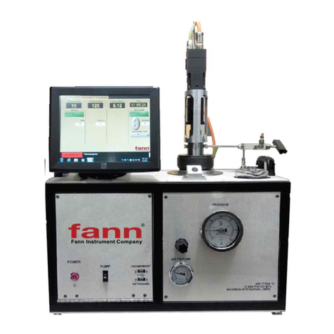
fann 520 HT User manual

© 2015 Fann Instrument Company
Model 520 HT Ultrasonic Cement Analyzer
Instruction Manual
Manual No. D01157216 Revision A
Instrument No. 102546636

Model 520 HT UCA
D01157216 Revision A, October 2015 2
Model 520 HT Ultrasonic Cement Analyzer Instruction Manual
©2015 Fann Instrument Company
Houston, Texas, USA
All rights reserved. No part of this work covered by the copyright hereon may be reproduced or
copied in any form or by any means (graphic, electronic, or mechanical) without first receiving the
written permission of Fann Instrument Company, Houston, Texas, USA.
Printed in USA.
The information contained in this document includes concepts, methods, and apparatus which may be
covered by U.S. Patents. Fann Instrument Company reserves the right to make improvements in
design, construction, and appearance of our products without prior notice.
FANN®and the FANN logo are registered trademarks of Fann Instrument Company in the United
States and/or other countries. All other trademarks mentioned in the operating instructions are the
exclusive property of the respective manufacturers.
Contact Fann Instrument Company
Phone
1-281-871-4482
1-800-347-0450
Fax
1-281-871-4358
Postal Address
Fann Instrument Company
P.O. Box 4350
Houston, Texas, 77210 USA
Shipping Address
Fann Instrument Company
14851 Milner Road, Gate 5
Houston, Texas, 77032, USA
Online
www.fann.com

Model 520 HT UCA
D01157216 Revision A, October 2015 3
Table of Contents
1 Introduction ..............................................................................................................5
1.1 Document Conventions....................................................................................6
2 Safety.......................................................................................................................7
2.1 Safe Pressurization..........................................................................................7
2.2 Safe Heating ....................................................................................................7
2.3 Safe Electrical Operation..................................................................................7
3 Features and Specifications .....................................................................................8
4 Installation..............................................................................................................10
4.1 Connecting the Drain Line..............................................................................10
4.2 Connecting an Uninterruptible Power Supply (UPS).......................................12
5 Using the Touchscreen Software............................................................................13
5.1 The Main Menu..............................................................................................14
5.2 Test Setup Menu............................................................................................15
5.3 New Temperature Profile ...............................................................................15
5.4 Instrument Setup Menu..................................................................................17
5.5 Diagnostics ....................................................................................................18
5.6 Running a Test...............................................................................................19
5.7 Stopping a Test..............................................................................................21
5.8 Using the USB Memory Module .....................................................................21
5.9 Networking.....................................................................................................22
5.10 Transit Time Calibration.................................................................................22
6 Front Panel Controls ..............................................................................................24
6.1 Hydraulic Pressure Controls...........................................................................24
6.2 Pneumatic Controls........................................................................................24
6.3 Electrical Controls and Displays.....................................................................25
7 Operation ...............................................................................................................26
7.1 Setting Up Automatic Pressure Control..........................................................27
7.2 Stopping a Test..............................................................................................28
7.3 Cleaning the Test Cell....................................................................................30
8 Interpreting Test Results ........................................................................................31
9 Troubleshooting and Maintenance .........................................................................32
9.1 Troubleshooting .............................................................................................32
9.2 Maintenance ..................................................................................................34
10 Warranty and Returns ............................................................................................35

Model 520 HT UCA
D01157216 Revision A, October 2015 5
1 Introduction
Cements are a critical element in the drilling, completion, workover, and
abandonment of wells. For each application, a cement slurry is designed with
specific properties and is given additives that provide predictable slurry density,
volume, viscosity, compressive strength, fluid loss, gas migration, and thickening
time. The Model 520 Ultrasonic Cement Analyzer (UCA) is used to provide a
history of the strength development of a cement slurry as it cures under elevated
temperature and pressure.
The UCA transmits an ultrasonic pulse through a cement slurry and measures the
travel time of the pulse through the slurry. The travel time of the pulse through the
slurry gives an indication of the compressive strength of the slurry. The
compressive strength, along with temperature and pressure, are monitored as a
function of time for the purpose of providing a strength history of a setting cement
slurry.

Model 520 HT UCA
D01157216 Revision A, October 2015 6
1.1 Document Conventions
The following icons are used as necessary in this instruction manual.
NOTE.Notes emphasize additional information that may be
useful to the reader.
CAUTION. Describes a situation or practice that requires operator
awareness or action in order to avoid undesirable consequences.
MANDATORY ACTION. Gives directions that, if not observed,
could result in loss of data or in damage to equipment.
WARNING! Describes an unsafe condition or practice that if not
corrected, could result in personal injury or threat to health.
ELECTRICITY WARNING! Alerts the operator that there is risk of
electric shock.
HOT SURFACE! Alerts the operator that there is a hot surface and
that there is risk of getting burned if the surface is touched.
EXPLOSION RISK! Alerts the operator that there is risk of
explosion.

Model 520 HT UCA
D01157216 Revision A, October 2015 7
2 Safety
Safe laboratory practices and procedures should be observed while operating and
maintaining the Model 520. Follow the instructions provided to avoid personal
injuries or damage to the equipment.
Always wear appropriate personal protective equipment (PPE) when operating or
maintaining the Consistometer.
2.1 Safe Pressurization
This Consistometer has pressurized air, water, and hydraulic lines that present a
hazard if not depressurized before maintenance or disassembly.
The hydraulic diaphragm pump and the pressure relief valve require compressed
air. Before working on any of these devices or connected air lines, shut off the
compressed air supply to the machine, and carefully relieve air pressure from the
machine.
2.2 Safe Heating
Before opening the pressure chamber, use the cooling system to lower the
temperature to at least 120°F (49°C). The machine uses domestic water as coolant.
Shut off the domestic water supply before servicing.
NEVER operate the heater on an empty chamber. The heater element will quickly
overheat and fail. To prevent smoke and possible fire, always fill the chamber and
pressurize before heating.
2.3 Safe Electrical Operation
Disconnect the power cable before attempting any electrical or mechanical
maintenance. Be aware that after the power switch is turned off, the electrical
terminals inside the panel will remain electrically energized.
Refer to the electrical schematic before performing any maintenance or
troubleshooting.
Always disconnect the power cable before attempting any repair.

Model 520 HT UCA
D01157216 Revision A, October 2015 8
3 Features and Specifications
The major features of the UCA are listed below:
•Easy to install.
•Completely self-contained. No need for pressure controllers, control boxes,
or computer
•All software is Windows®* based.
•Data may be plotted on a standard ink jet printer, stored on a USB flash
memory stick, or archived to an external computer via an Ethernet
connection.
•Tests are stored as .tdms files and may be retrieved and viewed. Text files
(.txt) may also be exported for interfacing with most word processors, text
editors, spreadsheets, and database programs.
•Touch screen control panel controls of data acquisition and temperature.
Temperature profile is displayed graphically before test starts to reduce
mistakes.
•Available with integral pump and relief valve for soak pressure control. It
does not require separate pressure controller.
•Unit may be operated with an optional uninterruptible power supply (UPS)
that will keep all functions (except heater) of the UCA operating for up to
one hour during power outages.
*”Microsoft” and “Windows” are registered trademarks of Microsoft Corp.

Model 520 HT UCA
D01157216 Revision A, October 2015 9
Table 3-1 Model 520 Specifications
Category Specification
Electrical
Input Voltage 230 VAC (+15%)
Input Power 2500W
Input Current 11 A
Input Frequency 50-60 Hz
Mechanical
Height 14.5 in. (36.8 cm)
Width 26 in. 66 cm)
Depth 15.3 in. (38.9 cm)
Weight 110 lb. (50 kg)
Environmental
Operating Temperature (32 to 120°F) 0-50°C
Operating Humidity 0-95% non-condensing
Heater
Heater Power 2,000 W
Heater Type Cast heater with cooling coils
Heater Control Solid state relay
Utilities – Water and Air
Compressed Air 100 psig (6.8 bar)
Cooling Water Pressure 100 psig (6.8 bar) maximum
Utility Inlets ¼ inch female NPT

Model 520 HT UCA
D01157216 Revision A, October 2015 10
4 Installation
Upon uncrating the instrument, verify that the instrument and any spare parts on the
packing list have been received and are undamaged.
Once the instrument has been moved to its desired location, air, water, and
electrical connections can be made. The air inlet, water inlet, and water drain
connections are each ¼ inch female NPT connections and are located on the lower
right rear of the instrument. A number of ¼ inch male NPT to 8mm tube fittings
are included for international locations.
It is good practice to leave space behind the instrument so that
qualified Fann personnel can have service access. If this is not
possible, try to make the unit easy to disconnect and move for
service.
Connect the coolant and pressurizing water to the connectors labeled COOLING
WATER and WATER INLET, respectively, on the rear panel of the instrument.
Each fitting has a ¼ inch female N.P.T. connection. The water must be clean and
free of debris that could cause failure of the pump or relief valve. A water filter is
included and must be installed on the water inlet to promote trouble free pump and
relief valve operation. Depending on the quality of the water supply, the filter may
need to be replaced more frequently. Follow the water filter manufacturer’s
recommended replacement interval. Neglecting to install the water inlet filter will
void the instrument warranty. Water inlet supply water must be filtered at 5 micron
or better and have a viscosity between 1–100 cst. Pump performance is affected by
many operating conditions. Extreme temperatures, pressures, and high duty cycles
will increase maintenance frequency. All units are lubricated at the factory with
silicone free semi-synthetic grease. After 2-3 months of normal (50% duty)
operation, the standard spool seals should be inspected for wear and re-lubricated.
Based on this inspection, future maintenance intervals can be planned and further
disassembly and lubrication of other moving seals may be necessary.
4.1 Connecting the Drain Line
Connect drain lines to the connectors labeled WATER DRAIN and COOLING
DRAIN on the rear panel of the instrument. The fittings have ¼ inch female
N.P.T. connections. The drain system must be capable of handling hot water up to
212 °F (100°C) and brief surges of up to 500°F (260°C) steam for short periods of
time during initial cooling of the instrument. If two or more UCA’s are connected
to a common drain line, it is recommended that the drain be 3/8 inch (10mm) inside
diameter, minimum. It is also recommended that the drain system be all metal.
Connect the air supply to the connector labeled AIR INLET on the rear panel of
the instrument. The fitting has a ¼ inch female N.P.T. connection. The air should

Model 520 HT UCA
D01157216 Revision A, October 2015 11
be dry and relatively free from dirt and oil. The air should be supplied at a pressure
of 20-100 psig (1.4-6.8 bar). Compressed nitrogen may also be used in place of the
compressed air if necessary. Drive air should be filtered between 5μ and 40μ and
have a maximum dewpoint of 50°F. Very wet air will wash out lubricant and cause
exhaust icing. Very dry air (dew point below 0°F) will dry out lubricant and cause
premature failure of spool o-rings.
If high pressure bottles of nitrogen or air are used to operate the
instrument, make certain that the pressure supplied to the
instrument does not exceed 100 psig (6.8 bar). Applying high
pressure gas to the instrument can cause tube rupture and
possible injury.
Electrical connections are made using the receptacle on the rear of the instrument.
A power cord is supplied with the instrument. Please observe the following
precautions when making the wiring connections.
Wiring should be completed by a qualified installer in accordance
with local electrical codes.
The instrument should be securely connected to a separate earth
ground. The ground wire must be larger in diameter than the
supply conductors
An 8BC or larger fire extinguisher to fight electrical and oil fires
should be placed within 50 feet of the consistometer.
Some components such as the touch screen LCD monitor may be removed from the
instrument prior to shipment and shipped in a separate container to prevent damage.
This device must be reinstalled before operating the instrument. The monitor
cables include one USB and one VGA cable which must be connected to the
control box and one AC power cable which must be connected to the 230 VAC
input on the monitor.

Model 520 HT UCA
D01157216 Revision A, October 2015 12
Before plugging the monitor into the rear of the UCA, make
certain power to the instrument is off.
If a printer is included with the instrument, it may be connected to the control box.
Connect the USB connector on the printer cable to the control box. The printer
must also be connected to a suitable power source. Refer to the printer
documentation for power requirements.
4.2 Connecting an Uninterruptible Power Supply (UPS)
This is applicable only if there are two receptacles on the rear of the unit labeled
UPS that may be used to connect an uninterruptible power supply (UPS). In the
event of a power failure, the UPS will operate all functions of the UCA, except the
heater, for up to one hour to prevent loss of test. To connect the UPS, select the
power cord supplied with the UPS and connect one end to the UPS input and the
other end to the UCA. The cord will fit only one receptacle. Locate the other
power cord supplied with the instrument and connect one end to the output of the
UPS and the other end to the other UPS receptacle on the rear of the UCA. Press
the ON button on the UPS. A green light will appear on the UPS when it is
operating properly. If the unit beeps and a red light comes on, a power failure has
occurred and the unit is being powered by the UPS. Note that if the POWER
switch is turned OFF and the UPS is not turned OFF, the instrument will not power
down.
If a UPS is not used, the cord must be installed between the two
rear panel receptacles or the instrument will not operate.
Before attempting to operate the instrument, it is recommended that the operators
read the remainder of the manual to become familiar with the UCA operation.

Model 520 HT UCA
D01157216 Revision A, October 2015 13
5 Using the Touchscreen Software
Touch screens were created to provide operators with an easy to use interface.
They allow the user to input and view data without a keyboard or mouse. The
touch surface is able to detect contact for selecting options.
Most any object may be used on the touch-screens. Experimentation will quickly
show which objects will activate the screen and which will not. It is important to
note the touch surface does NOT use pressure to detect input. A light touch is all
that is needed. In addition sharp instruments (such as pencils, pens, screwdrivers,
etc.) should not be used as they may damage the touch surface.
The purpose of the touch screen is to provide the user with a single interface to the
instrument. Temperature control, instrument setup, and current test data are
accessed through the touch screen. This eliminates the need to individually
program separate temperature controllers or other off-site software to begin running
a test. Additionally, the touch screen allows the user to access current information
from the instrument during a test. Each instrument is complete and requires no
additional software or hardware to function.
The software is designed to be intuitive to the user. In addition to the options, the
different screens include directions and helpful hints to allow the user to quickly
setup and run the instrument. The first-timer will find an easy to follow path to set
up a test. Most users will become highly proficient within a very short time.

Model 520 HT UCA
D01157216 Revision A, October 2015 14
5.1 The Main Menu
The main menu is the starting point for the instrument. From here, users may start
new tests, setup test parameters, setup instrument parameters, or view an old test.
Located at top left is the current temperature reading for the thermocouple. Current
pressure is also displayed. The Exit button is used to stop the UCA software and
go into the Windows®operating system.
As noted in the instructions on the screen, all the user needs do is touch a button to
begin.
START TEST – Pressing this button begins a test. The instrument takes the current
test parameters and begins a new test. If a temperature profile has been
programmed, a screen will prompt the user to turn on the heater. Once a test has
started the main testing screen will be displayed.
TEST SETUP – This button takes the user to the Test Setup Screen. Here the user
may enter test parameters for the instrument. Test name, cement parameters, UCA
algorithm, and Temperature Control are all accessed through this screen.
INSTRUMENT SETUP – This button takes the user to the Instrument Setup
Screen. From this screen the user may verify transducer signal, calibrate the
instrument, or archive the data to a USB memory module or network drive.
VIEW TEST – This button allows the user to view any previously stored test. The
software looks for the tests in the C:\Fann directory and you will be prompted to

Model 520 HT UCA
D01157216 Revision A, October 2015 15
select a file. Use care when choosing a file name so you will be able to retrieve it if
desired.
5.2 Test Setup Menu
From this menu the user can setup the parameters for the next test.
5.3 New Temperature Profile
On the temperature setup screen is a standard numeric keypad. On the left side are
three values that define a ramp. Once a ramp is entered the user may advance to
the NEXT STEP or press DONE to finish.
When finished, a graph of the desired temperature ramp is displayed. The user may

Model 520 HT UCA
D01157216 Revision A, October 2015 16
accept the current profile and continue or cancel to make further modifications.
Once the first ramp has been entered, press the NEXT STEP button to proceed to
the next ramp or DONE to end the profile programming. If you end the
programming at this point and start the test the temperature will reach set point and
then fall because there was no second ramp or soak entered.
From this screen a second ramp may be entered or the user can enter a soak. To
initiate a soak the user must use the Soak keypad button in the Ramp Time box.
This will tell the computer to hold continuously at the programmed temperature. If
you enter Soak as the time, the Start Value temperature and the End Value
temperature must be the same. After entering all of your ramps and soak, you may
press Done to complete the programming process. If you press Done, a graph will
be displayed showing exactly what you have entered for your temperature profile as
shown below:
From this screen the user may press OK if the graph is correct or Change to go
back to the programming screens to correct any programming errors. If Accept is
pressed the TEST SETUP screen will be displayed again. From here press DONE
and the main menu will appear. Press START TEST to begin the test or any of the
other buttons to change alarm values, slurry type, etc.
5.3.1 Alarm Values –
The Alarm Values Button allows the user to enter unlimited alarm values for
compressive strength and test time. The PC will notify the user when these values
have been reached and at what time they were reached. The highest value entered
here will become the default AUTO-SHUTDOWN value during a test.

Model 520 HT UCA
D01157216 Revision A, October 2015 17
5.4 Instrument Setup Menu
From this menu the user can run diagnostics on the ultrasonic transducer circuitry
to determine if everything is functioning properly. This menu is also used to move
data files from the UCA computer to another PC in order to free space in the UCA
memory.
ARCHIVE DATA FILES – Select this command to move tests from the UCA to
the USB memory module. If the instrument reports a “Disk Full” message, it will
be necessary to do this before additional tests may be run. After this step is
completed, the stored tests on the UCA are moved then deleted. After this button is
pressed a message box will appear indicating which files were copied from the
UCA to the storage device.
CALIBRATE – The Calibrate button gives the operator the option of calibrating
temperature, pressure, or transit time.
To calibrate the transit time, the cylinder must be COMPLETELY full of water
with no air bubbles inside the cell.

Model 520 HT UCA
D01157216 Revision A, October 2015 18
Never calibrate transit time with a cement slurry or steel bar from
other devices.
5.5 Diagnostics
The Diagnostics button displays a diagnostic screen where the user may pulse the
transducer and display the waveform on the screen. This tool allows the user to
quickly verify transducer operation. The peak of the transducer should be well
above 200 with water in the vessel. If the pulse amplitude is less than 200 with
water in the cell, the UCA will not function properly and an error message will be
displayed.

Model 520 HT UCA
D01157216 Revision A, October 2015 19
5.6 Running a Test
Once a test has begun, a RUN-TIME MENU of current values will be shown. The
user may control all available parameters of the instrument from this menu.
Under the Pressure column, the user can turn the water supply to the pressure
vessel on or off and can turn the pump on when the cylinder is filled.
Under the Temperature column, the user can select between AUTO and MANUAL
temperature control. When in MANUAL mode, the user can adjust the temperature
set point as well as turn cooling on/off.

Model 520 HT UCA
D01157216 Revision A, October 2015 20
Under the Time column, the user can STOP TEST or select SHUTDOWN
parameters for the Auto Shutdown feature. The user can select between Time (hr)
or Compressive Strength and adjust the target value using the Shutdown Value
control. When the test reaches the Shutdown Value the test will be stopped and
cooling automatically turned on.
By selecting the VIEW LIVE CHART tab at the top of the screen, the user can
view real-time data in chart form. From this screen, the user may print the chart at
any time by pressing the PRINT button located at the bottom of the screen. (Please
note that a printer must be connected to the instrument before trying to print.)
Pressing the PRINT button displays the full TEST VIEWER screen where the user
may select specific printing options such as header/footer information before
printing to any installed printer.
A complete table of numerical data can also be viewed here by selecting the DATA
tab located on the left side of the screen in the Test Viewer.
Return to the test controls by selecting CLOSE. This will not have any effect on the
actual testing process and can be opened / closed at any time.
The TEST SETUP tab is simply a review of parameters entered during the TEST
SETUP and cannot be changed.
If there is some question as to whether the instrument is producing the desired
ultrasonic waveform, the user may press the PRINT WAVEFORM button
Table of contents
Other fann Measuring Instrument manuals
Popular Measuring Instrument manuals by other brands

Underground Magnetics
Underground Magnetics Mag 9 manual

PCE Health and Fitness
PCE Health and Fitness FG 20SD manual

ProCharger
ProCharger LADEAMPEL Instructions for installation and use

Reed Instruments
Reed Instruments R8080 instruction manual

Cropico
Cropico DO5003 user manual

Ashcroft
Ashcroft a4a Installation and maintenance manual