fann DNA 102410489 User manual

Data Network Adapter (DNATM) System
Instruction Manual
Manual No. D00981262, Revision A
Instrument No. 102410489

DNATM System Instruction Manual
D00981262 Revision A, May 2015 2
DNA™ System Instruction Manual
©2015 Fann Instrument Company
Houston, Texas, USA
All rights reserved. No part of this work covered by the copyright hereon may be reproduced or
copied in any form or by any means (graphic, electronic, or mechanical) without first receiving the
written permission of Fann Instrument Company, Houston, Texas, USA.
Printed in USA.
The information contained in this document includes concepts, methods, and apparatus which may be
covered by U.S. Patents. Fann Instrument Company reserves the right to make improvements in
design, construction, and appearance of our products without prior notice.
FANN®and the FANN logo are registered trademarks of Fann Instrument Company in the United
States and/or other countries. All other trademarks mentioned in the operating instructions are the
exclusive property of the respective manufacturers.
“Microsoft” and “Windows” are registered trademarks of Microsoft Corp.
Contact Fann Instrument Company
Phone
1-281-871-4482
1- 800-347-0450
Fax
1-281-871-4358
Postal Address
Fann Instrument Company
P.O. Box 4350
Houston, Texas, 77210 USA
Shipping Address
Fann Instrument Company
14851 Milner Road, Gate 5
Houston, Texas, 77032, USA
Online
www.fann.com

DNATM System Instruction Manual
D00981262 Revision A, May 2015 3
Table of Contents
1 Introduction ..............................................................................................................5
1.1 Fann Equipment Compatible with DNATM System ............................................5
1.2 Document Conventions....................................................................................6
2 Safety.......................................................................................................................7
3 Features and Specifications .....................................................................................8
3.1 System Features..............................................................................................8
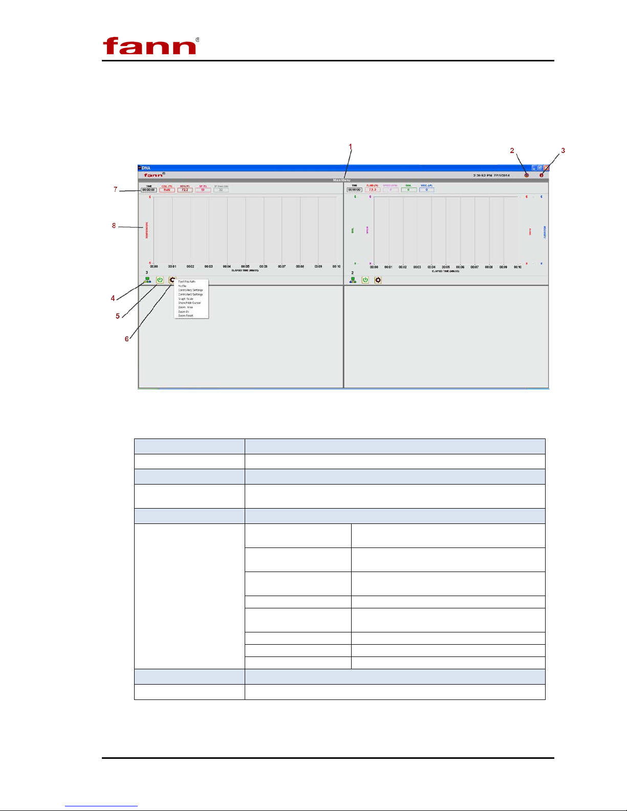
3.2 DNATM Software...............................................................................................9
4 Installation..............................................................................................................16
4.1 Installing the Software....................................................................................16
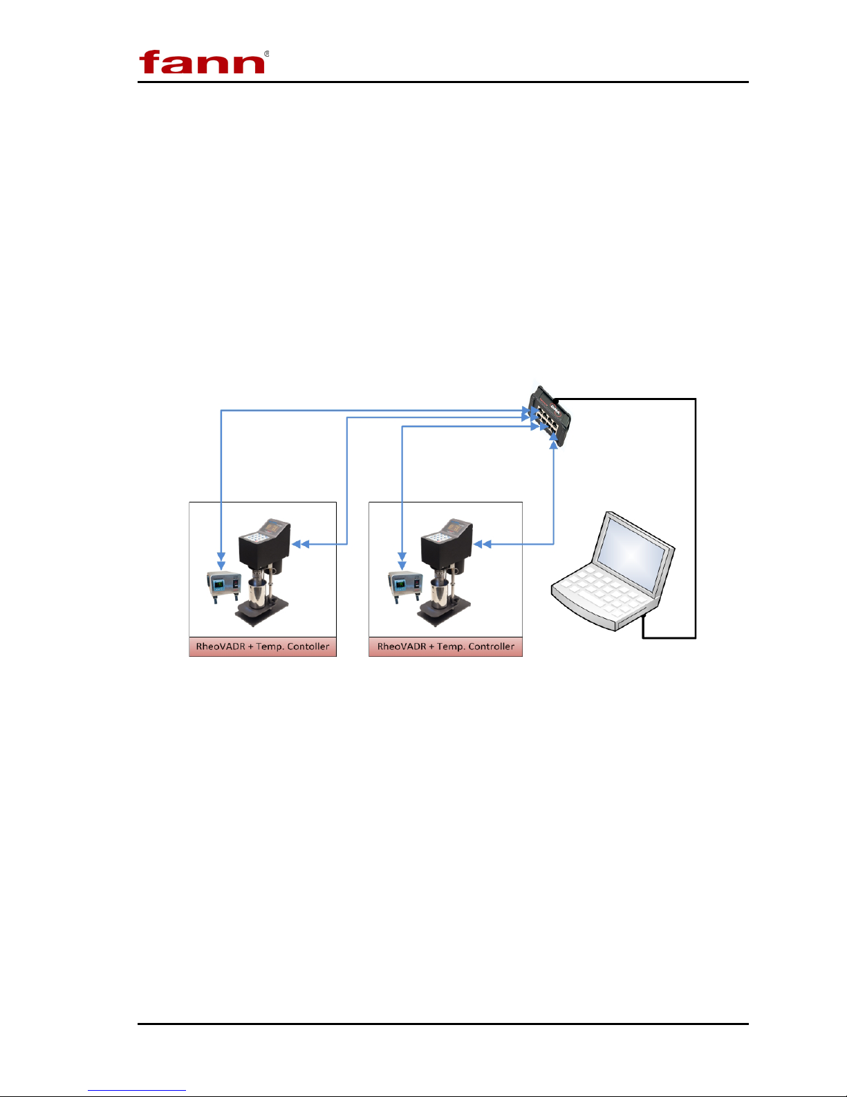
4.2 Connecting the DNATM Box to Computer........................................................17
4.3 Connecting the DNATM Box to Fann Machines...............................................17
4.4 Collecting Communication Addresses............................................................17
4.5 Configuring the DNATM Box............................................................................19
4.6 Changing Default Settings..............................................................................21
4.7 Updating the Software....................................................................................22
4.8 Configuring the Instruments ...........................................................................25
5 Test Programming and Editing...............................................................................33
5.1 Basic Profiles .................................................................................................33
5.2 Saved Profiles................................................................................................34
5.3 Heat Profiles ..................................................................................................34
5.4 Rheology Profiles...........................................................................................35
5.5 Multiple Profiles..............................................................................................36
5.6 Starting a Test................................................................................................37
6 Test Analysis.........................................................................................................39
7 Troubleshooting and Maintenance .........................................................................40
8 Parts List................................................................................................................41
9 Warranty and Returns............................................................................................42
9.1 Warranty ........................................................................................................42
9.2 Returns ..........................................................................................................42

DNATM System Instruction Manual
D00981262 Revision A, May 2015 4
List of Figures
Figure 3-1 DNATM System Example Setup......................................................................8
Figure 4-1 DNATM System with RheoVADR®s and Temperature Controllers.................16
Figure 6-1 Graphical Results ........................................................................................39
Figure 8-1 DNATM Box ..................................................................................................41
List of Tables
Table 3-1 Main Screen Menus and Functions..............................................................10
Table 3-2 Profile Screen Functions...............................................................................12
Table 7-1 Troubleshooting Guide..................................................................................40
Table 8-1 Data Network Adapter Assembly, P/N 102410489........................................41

DNATM System Instruction Manual
D00981262 Revision A, May 2015 5
1 Introduction
Fann® Data Network Adapter System is a proprietary hardware and software
system that adds capabilities to Fann instruments by connecting them to a computer
operating Fann’s exclusive Data Acquisition and Control software. The software
facilitates communication, control, and data collecting for up to eight machines.
Multiple units can be joined to act as an integrated system (e.g.,
RheoVADR® Rheometer with Model 741 Temperature Controller).
This system is ideal for users who want to
•automate several tests simultaneously and collect data for every test
•combine several machines to perform individual complex tests
1.1 Fann Equipment Compatible with DNATM System
The DNATM System works with RheoVADR®Rheometer, Model 741 Temperature
Controller, and HT4700 HPHT Filter Press. In the future, more Fann instruments
will be available for connecting to DNATM System.

DNATM System Instruction Manual
D00981262 Revision A, May 2015 6
1.2 Document Conventions
The following icons are used as necessary in this instruction manual.
NOTE.Notes emphasize additional information that may be
useful to the reader.
CAUTION. Describes a situation or practice that requires operator
awareness or action in order to avoid undesirable consequences.
MANDATORY ACTION. Gives directions that, if not observed,
could result in loss of data or in damage to equipment.
WARNING! Describes an unsafe condition or practice that if not
corrected, could result in personal injury or threat to health.
ELECTRICITY WARNING! Alerts the operator that there is risk of
electric shock.
HOT SURFACE! Alerts the operator that there is a hot surface and
that there is risk of getting burned if the surface is touched.
EXPLOSION RISK! Alerts the operator that there is risk of
explosion.

DNATM System Instruction Manual
D00981262 Revision A, May 2015 7
2 Safety
Safe laboratory practices and procedures should be observed while operating and
maintaining the DNATM system. This section lists some precautions to follow.
Before runnng a test, review the safety precautions of connected
equipment (e.g., RheoVADR®Rheometer, Model 741 Temperature
Controller, and HT4700 Heating Jacket.).
DNATM should always be used on a grounded circuit.
Electrical connections to and from the DNATM box should be
properly insulated and must not be compromised.

DNATM System Instruction Manual
D00981262 Revision A, May 2015 8
3 Features and Specifications
The DNATM System includes the DNATM box (USB to RJ45) with USB computer
connector, software, and two 10-ft CAT5 RJ485 cables.
The box has ports for connecting eight individual machines or combinations of
machines (up to eight, maximum).
The DNATM System works with RheoVADR® Rheometer, Model 741
Temperature Controller, and HT4700 HPHT Filter Press. In the future, more
DNATM compatible instruments will be available from Fann.
Refer to Figure 3-1 for a typical setup:
Figure 3-1 DNATM System Example Setup
3.1 System Features
•Combines units to act as one, increasing overall capabilities
•Schedules for time, temperature, speed, and data rate
•Provides temperature ramping
•Saves test profiles and combines profiles to run complex schedules

DNATM System Instruction Manual
D00981262 Revision A, May 2015 9
3.2 DNATM Software
The DNATM software offers the following features:
•Collects data from various instruments
•Controls several unique instruments
•Graphical display of set points, real-time values, elapsed time and more
variables
•Records data at 100 ms, 500 ms, 1 s, 2 s, 5 s, 10 s
•Audible alerts for end of test, temperature set point, and other important
steps or events
•Compatible with Fann Data Manager for organizing and printing data or
exporting it to a spreadsheet
•System updates available
•Operating system— Microsoft®Windows®7

DNATM System Instruction Manual
D00981262 Revision A, May 2015 10
3.2.1 Main Screen
These menu items are described in detail in following sections.
Main Screen
Table 3-1 Main Screen Menus and Functions
1 Main Menu Click to show more options
2 Updates Check for software updates
3 Information Displays software version
4 Connection Status
Green = connected
Red = disconnected or an error
5 Start/Stop Click to start (green) or stop (red).
6 Machine Settings
Test File Path Location where files saved on your
computer
Profile
Design test using steps, temperature,
recording rate, and speed
Settings Specify settings for each connected
machine
Graph Scale
Adjust graph scale
Show/Hide Cursor
Place cursor (vertical dotted line) on
graph to see values
Zoom Area
Set area on graph to view
Zoom In
Increase view
Zoom Reset
Change view to normal
7 Indicators Displays real-time test data
8 Graph Real-time graph displays while test in progress

DNATM System Instruction Manual
D00981262 Revision A, May 2015 11
3.2.2 Main Menu Expanded
Click Main Menu to see the display options.
Main Menu Expanded View
•shows machine windows 1, 2, 3, and 4.
•switches between display options – windows 1 to 4 or 5 to 8
•shows machine windows 5, 6, 7, 8.
•expands the selected window for closer view.
•opens Settings (discussed in Section 4).
•Click the gray area to close the expanded view of the main menu.
3.2.3 System Updates
Click the update icon to check for new software versions. Then follow the
instructions shown to complete the update (Section 4).

DNATM System Instruction Manual
D00981262 Revision A, May 2015 12
3.2.4 Profile Screen
Click Machine Settings gear (drop down). Select Profile.
Each machine has its own profile template. These illustrations show templates for
RheoVADR®Rheometer and HT4700 Filter Press.
Instructions for creating profiles are provided in Section 5.
RheoVADR®Profile
HT4700 Profile
Table 3-2 Profile Screen Functions
Step Type Click the
+
to choose step type
Time Set time in hours, minutes, and seconds for step
Speed Set speed (rpm); range 0.01 to 999.9 rpm
Record Interval Enter recording rate: 100, 200 & 500 ms; 1, 5, & 10 sec
Temperature Enter set point temperature (degrees F or C)
Repeat Enter number of repeats for the profile
Open Open to select saved profiles
Save Save profiles for reuse
Clear Erase entries
Alarm Click alarm icon to turn ON; click Xto turn OFF

DNATM System Instruction Manual
D00981262 Revision A, May 2015 13
3.2.5 Settings Tabs
Machine
Assign a unique identification to each machine in the Machine ID box. Then,
select the model from the dropdown menu (Model 741 Temperature Controller,
RheoVADR®Rheometer, or HT4700 HPHT Filter Press).
To activate communication between the DNATM system and the machines,
configure each machine.
Click the configuration gear (Config) and follow the instructions. Detailed
configuration instructions are given in Section 4.
Settings
Machine
Test Header
This section contains frequently used information— lab name and customer names.
The software will automatically fill (or prompt) certain fields when you set up your
tests. The lab name only needs to be entered once. During test setup, the software
will show this list of customers. New customer names are added to the bottom of
the list and sorted alphabetically when the OK button is clicked.
Settings
Test Header

DNATM System Instruction Manual
D00981262 Revision A, May 2015 14
General
The illustration below shows default settings. Refer to Section 4
for completing the General tab for different machines.
Temperature Settings
Set the preferred units (degrees Celsius or Fahrenheit) and test parameters in this
section.
The temperature units entered in Temperature Settings should
match the units selected on the machine. For example, if you
select Celsius in the software, then you need to select Celsius on
the RheoVADR®Rheometer.
Port Settings
•Select the DNATM box(es) to be activated— COMS(number). The COMS
number will be given when you activate the DNATM box.
•Baud Rate is always 19200.
Settings
General

DNATM System Instruction Manual
D00981262 Revision A, May 2015 15
3.2.6 Graph Settings
Graph Scale
(Machine Settings gear > Graph Scale)
•To change the axes scale range, enter the desired values.
Graph Scale: Axis Scales
Show/Hide Cursor
•The cursor is a vertical line that can be moved to any location on the graph
by using the mouse.
•Place the cursor anywhere on the graph to display values in the indicators
section (main screen).
Zoom Area
•Draw a rectangle around the area of the graph you want to enlarge.
Zoom In
•This feature increases the selected rectangular area. The x/y axes rescale to
display this area.
Zoom Reset
•This option changes the graph to full scale view.

DNATM System Instruction Manual
D00981262 Revision A, May 2015 16
4 Installation
The DNATM and connected equipment can generally be arranged to suit the
available space and the desires of the lab personnel, consistent with any established
work processes. Some environments encourage a right-to-left flow, while others a
left-to-right flow.
An example setup is shown below.
Figure 4-1 DNATM System with RheoVADR®s and Temperature Controllers
4.1 Installing the Software
A computer that operates on Windows®7 is required. The DNATM assembly does
not include a computer and monitor.
1. Insert the software USB flash drive (included).
2. If the installation process does not automatically begin, click Start, and then
Run. Browse to find the setup program. Select the setup program, and then
click to open.
3. When the setup program appears in the Run dialog box, select OK.
4. Wait for the software to install.

DNATM System Instruction Manual
D00981262 Revision A, May 2015 17
5. Select where you want to install the software.
6. Continue with the installation process, following the prompts, and clicking
Next when required.
7. When the software installation is complete, click Finish.
The DNATM box can now be connected and the software can be
started by clicking on the DNATM software desktop icon. (screen
capture of icon)
4.2 Connecting the DNATM Box to Computer
Connect DNATM cable to USB port on the computer.
4.3 Connecting the DNATM Box to Fann Machines
Connect the RJ485 cable from the instrument port (labeled RS485 or Data) to a
port on the DNATM box.
4.4 Collecting Communication Addresses
Each instrument must be assigned a unique address.
RheoVADR®Communication Address
Communication Address on RheoVADR®Rheometer

DNATM System Instruction Manual
D00981262 Revision A, May 2015 18
•To enter SETUP mode, press and hold STOP, and then turn on the power.
•Wait for the SETUP menu to appear.
•Press the blue key 4 to enter the address in the number range 001 to 255.
RheoVADR®units come with the address set to 110 in manufacturing. Each
RheoVADR®connected to the DNATM will need a unique address.
Model 741 Communication Address
Eurotherm Display
•Hold the Page button (~ six seconds) until Level 3 appears.
•Quickly press the Raise (up arrow) button until Config appears, and then wait
until Code appears.
•Use the up or down arrows to set the Code to 7. Wait until Config appears.
•Press the Page button multiple times until Comms appears.
•Press the Scroll button until id appears. Then set the id to rs485 using the
arrow keys.
•Press the Scroll button until ADDR appears. Then set the desired address using
the arrow keys.
•Press the Scroll button until BAUD appears. Then set the baud rate to 19.20
using the arrow keys.
•Press and hold the Page button until Config GOTO appears. Then press the
arrow keys to go to Level 1.
•Wait for the Eurotherm display to return to the main screen (shown above).

DNATM System Instruction Manual
D00981262 Revision A, May 2015 19
HT4700 Communication Address
Watlow Display
•Hold both arrow keys at the same time until Set appears.
•Scroll using the down arrow until CoM appears.
•Press the Advance Key until Pcol appears.
•Scroll using the down arrow until Mod appears if necessary.
•Press the Advance Key until Ad.M appears.
•Scroll using the down arrow to change the address if necessary.
•Press the Advance Key until baud appears.
•Scroll using the down arrow to change the baud rate to 19.2 if necessary
•Press the Infinity Key (∞) twice to return to the main display.
4.5 Configuring the DNATM Box
A DNATM box needs to be configured only once before using for
the first time.
Start the DNATM software by clicking on the icon on your desktop. Or browse to
find the Fann folder on your computer and then click on the DNATM icon.

DNATM System Instruction Manual
D00981262 Revision A, May 2015 20
Wait for the startup screen to appear.
On the bottom of the DNATM box, you will find its activation key. Enter the key as
shown in the example.
Press Activate. The software will confirm that the DNATM box is activated and
will provide the port name (example below).
From the Main Menu, click the Settings icon in the upper right corner.
A pop up for Settings will appear.
Table of contents
Popular Network Card manuals by other brands

Encore
Encore ENL832-TX-RE user guide

Asus
Asus P5Q3 Deluxe WiFi-AP n user guide

National Instruments
National Instruments NI 9229 operating instructions

Cisco
Cisco MGX-FRSM-2CT3 Configuration guide

Rockwell Automation
Rockwell Automation Allen-Bradley 1609-ENET quick start

Middle Atlantic Products
Middle Atlantic Products UPS-IPCARD user manual