Fantic Motor TF 250 2012 User manual


2
WARNING
It is recommended, after the first hours of use, to check all the torques with particular attention to:
A Front / Rear brake caliper
B Wheels axle
C Rear sprocket
D Engine bolts
E Rear suspension mounting nuts
F Wheels spokes
G Rear frame
The vehicle is equipped by catalytic exhaust (accredited Euro3) that can catch up high temperatures. Absolutely avoid the contact with body parts,
clothes inflammable materials !
WARNING
If necessary consult a FANTIC MOTOR dealer.
The technical information and specifications for maintenance contained in this handbook were correct at the time of going to press. FANTIC MOTOR
reserves the right to change the specifications, design data and necessary equipment at any time without notice. No part of this publication may be
abridged or translated without the manufacturer’s approval. FANTIC MOTOR cannot be held liable for any errors or omissions. All rights reserved.

3
This handbook is an integral part of the vehicle and must accompany it if resold.
FANTIC MOTOR reserves the right to make changes to the models described in this handbook without notice, while guaranteeing the essential features
described and shown herein.
No part of this handbook may be reproduced without the prior permission of the Manufacturer.
FANTIC MOTOR cannot be held liable for any copying or printing errors in this handbook.
GENERAL CONTENTS AND CONSULTATION
All the specifications and helpful instructions for normal use and maintenance of the vehicle are given in the handbook.
It is advisable to contact our Authorised Dealers for maintenance and any repairs, since they guarantee a prompt and precise service and always use
original spare parts.
MANUFACTURER’S DATA AND EDITION
FANTIC MOTOR
via Al Bigonzo, 15
31030 – Dosson di Casier (TV) Italy
Tel. +39 0422 634192/490636
Fax +39 0422 630491/490620
E-mail: info@fanticmotor.it
www.fanticmotor.it
Edition: 01/2012
FOREWORD

4
IMPORTANT NOTICE
Read this Manual carefully. You will nd it contains all the necessary informa-
tion for your safety, and that of other persons, as well as guaranteeing the
correct conservation and maintenance of the FANTIC MOTOR motorcycle
that you have just acquired.
You will nd all the necessary instructions for the correct riding and control
of this vehicle are set out below. Each message is preceded by a symbol with
the following meaning.
WARNING
This warning symbol identies special instructions or procedures which, if
not correctly followed, could result in personal injury or even death.
CAUTION
This symbol identies instructions or procedures which, if not followed
strictly, could result in damage to or destruction of equipment.
NOTE
This note symbol indicates points of particular interest for more ecient
and convenient operation.
Motorcycle riding, if improverly conducted, has the potential to cause envi-
ronmental problems as well as conicts with other people. Responsible riding
use of your motorcycle will ensure that these problems and conicts do not
develop.
recommends the use of lubricants and products
.

5
TABLE OF CONTENTS
Warning...................................................................................................... 2
Foreword ................................................................................................... 3
Important notice .................................................................................... 4
Table of contents.................................................................................... 5
Specications........................................................................................... 6
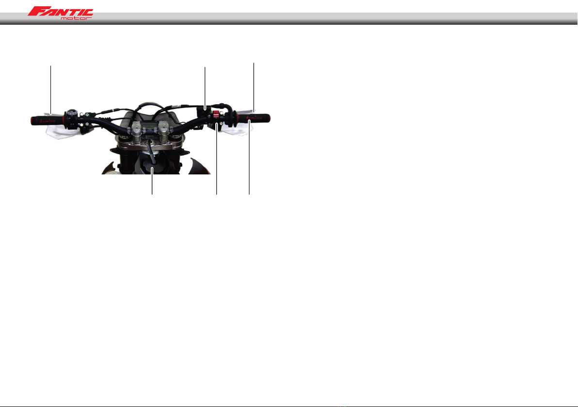
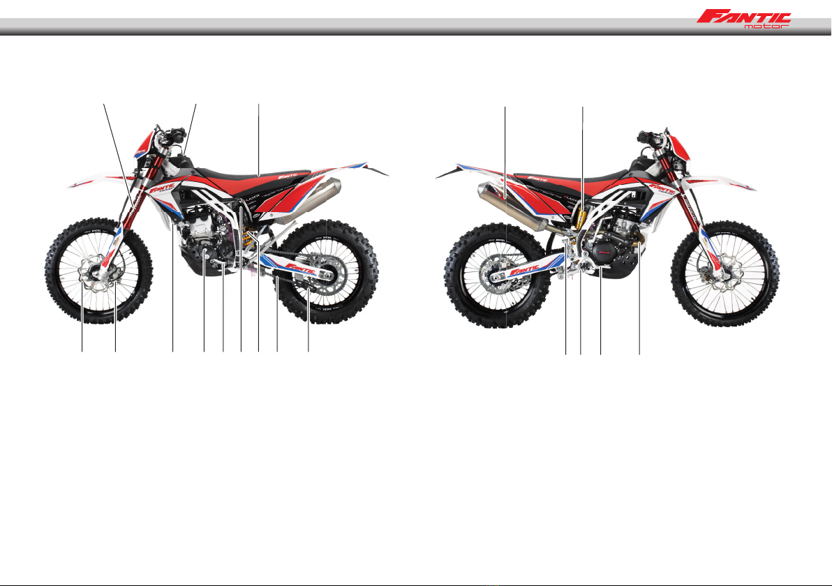
Location of components...................................................................... 8
Side Stand ................................................................................................. 10
Fuel .............................................................................................................. 10
Serial Number.......................................................................................... 11
Homologation Plate .............................................................................. 11
Starting the engine................................................................................ 12
Stopping the engine ............................................................................. 12
Cold starting............................................................................................. 13
Hot starting .............................................................................................. 13
Shifting gears........................................................................................... 13
Stopping the motorcycle..................................................................... 14
Riding during the Break-In Period.................................................... 14
Maintenance Schedule......................................................................... 15
Battery ........................................................................................................ 16
Cooling System ....................................................................................... 17
Spark Plug ................................................................................................. 19
Air Cleaner................................................................................................. 21
Throttle Cable .......................................................................................... 22
Clutch.......................................................................................................... 23
Exhaust System ....................................................................................... 23
Drive Chain Guide .................................................................................. 24
Handlebar ................................................................................................. 26
Brakes ......................................................................................................... 26
Steering...................................................................................................... 28
Steering blockage .................................................................................. 29
Front Fork .................................................................................................. 29
Rear suspension...................................................................................... 30
Wheels........................................................................................................ 32
Cleaning..................................................................................................... 33
Bolts and nuts tightening.................................................................... 34
Lubrication................................................................................................ 36
Engine oil................................................................................................... 37
Suspension tune-up.............................................................................. 39
Spare parts availible .............................................................................. 43
Preparation for competition............................................................... 43
Storage....................................................................................................... 44
FANTIC MOTOR Multifunction Instructions .................................. 45
Troubleshooting ..................................................................................... 51
Electric Schemas..................................................................................... 55
Warranty Manual .................................................................................... 56
Fast guide.................................................................................................. 58
Lubricants table ...................................................................................... 59

6
SPECIFICATIONS
ENGINE 4 stroke, single cylinder, DOHC 5 valves, liquid cooled
Displacement 249 cc
Bore and stroke 77 x 53,6 mm.
Fuel supply Carburatore Keihin FCR MX37
TRANSMISSION
Transmission type 5 speed
Clutch type Multi disc wet clutch
Secondary drive Chain driven
Gear ratio 1ª 2.385 (31/13)
2ª 1.750 (28/16)
3ª 1.353 (23/17)
4ª 1.095 (23/21)
5ª 0.895 (17/19)
Primary reduction 3.353 (57/17)
Final reduction 3.846 (50/13)
Overall drive ratio 11,5 (5ª gear )
Transmission oil Capacity 1.300 c.c.
Type SAE 5W40 API SG
CHASSIS
Type Cromoly steel frame
Tire size Front 90/90 x 21 (120/60 x17 motard version)
Rear 140/80 x 18 (150/60 x17 motard version
Suspension Front
ø 48 mm inverted fork with closed cartidge and shock preload regulation
Rear Progressive system with single multi-adjustment shock absorber
Suspension stroke Front 305 mm
Rear 298 mm
Front fork oil Tra SAE 5 e 7,5 (check manufacturer’s information)
Front fork oil level 320cc

7
BRAKES
Type Front, Rear Disk brakes, pump and double callipers / simple
Eective disc diameter Front 260 mm
Rear 220 mm
DIMENSIONS
Overall height 1260 mm
Overall length 2260 mm
Overall width 825 mm
Minimum height 340 mm
Wheelbase 1465 mm
Fuel tank capacity 7 litres
(Specications subject to change without notication, also possibly not applicable in some countries).

8
LOCATION OF COMPONENTS
14
5
623
1 - Clutch handle
2 - Engine start button
3 - Fuel tank cap
4 - Front brake uid tank
5 - Front brake handle
6 - Throttle control

9
7 - Exhaust bend
8 - Front suspension
9 - Radiator
10 - Fuel tank
11 - Air lter
12 - Seat
13 - Front brake disk
8 10 12
14 9 24 16 11 19 181713
20 21
15 22 22 7
14 - Front brake callipers
15 - Rear brake uid tank
16 - Shift pedal
17 - Rear shock absorber
18 - Chain guide
19 - Chain
20 - Silencer
21 - Rear shock absorber gas tank
22 - Tie rod and rocker suspension
23 - Rear brake pedal
24 - Engine oil cap

10
SIDE STAND
To set the side stand only turn it until it contacts the stopper, then the side
stand will be parallel to the ground and rest securely.
The side stand will return to its original position by means of the double
spring. The function of the double spring insures that, when the side stand is
down, the rest position is stable and above all secure; moreover, it also returns
the side stand to its original position.
(A)
(B)
(A) - Side stand.
(B) - Double spring.
NOTE
Do not start the engine or ride the motorcycle when the side stand is
down.
FUEL
The Fantic Motor TF250 has a four stroke engine and requires 98 octane, unle-
aded petrol.
Fuel Tank Capacity : 7 l
(B)
(A)
(A) - Fuel tank cap.
(B) - TVapor outlet tube.
The fuel tank cap is of the quick-release type.
To open the fuel tank cap, lift the plated latch and turn cap counter-clockwise.
To close it, turn the cap clockwise and lower the latch.
NOTE
It is recommended that the rubber seal should be checked thoroughly to
insure it is airtight.

11
RECOMMENDED FUEL
Use lead-free petrol with an octane rating equal to or higher than that shown
in the table.
OCTANE RATING METHOD MINIUM RATING
Antiknock Index (RON+MON)/2 90
Research Octane No. (RON) 98
NOTE
If knocking or pinging occurs, try a dierent brand of gasoline or higher
octane grade.
WARNING
Gasoline is extremely ammable and can be explosive under certain condi-
tions. Always stop the engine and do not smoke. Make sure the area is well
ventilated and free from any source of ame or sparks; this includes any
appliance with a pilot light.
SERIAL NUMBER (A)
It is stamped on the steering pipe. It indicates the frame number registered
for this motorcycle.
HOMOLOGATION PLATE (B)
This motorcycle carries its corresponding homologation plate where it also
shows the serial number, and this data must match the information registered
in the motorcycle documents.
(A)
(B)

12
STARTING THE ENGINE
1. Make sure the motorcycle is in the neutral position.
2. Press button (A) to turn on the electrical circuit, so that the motor may be
started.
(A)
3. Without using the throttle, press the electric start button (B).
(B)
STOPPING THE ENGINE
1. Shift the transmission into neutral.
2. After accelerating lightly, cut the gas completely and press button (C). The
electrical circuits are closed.
(C)

13
SHIFTING GEARS
The transmission is a 5 speed, of the return shift type. A return shift means
that to go from rst gear to third gear it must go rst through the second
gear, that is to say that it upshifts gears one by one. To engage rst gear from
neutral, pull the clutch lever in and push down on the gearshift pedal, then
release the gearshift pedal and gently release the clutch lever.
CAUTION
When shifting gears, press rmly on the gearshift pedal to ensure a positive
shifting. Careless, incomplete shifts can cause the transmission to jump out
of gear and cause engine damage.
(A)
(A) - Gearshift pedal.
COLD STARTING
To do the cold start, pull the starter.
- There is no need to use the throttle, simply start the engine. Note that the
engine will start after a certain number of revolutions.
After the warming time, you can pull out the cold starter. With the cold start,
the bike warm slowly without damages.
NOTA
If the engine is drowned, you can pres the hot starter and on the same
time, press the kick pedal 10 at 20 times. When the engine is dry, you can
start normally.
HOT START
Don’t use the cold start and don’t touch the trotle. Press the hot starter and
start the engine with the kick or the electric starter. When the engine is run-
ning, pull out the hot start.

14
STOPPING THE MOTORCYCLE
For maximum deceleration, close the throttle (A) and apply both front and
rear brakes. Disengage the clutch as the motorcycle comes to a stop. Inde-
pendent use of the front or rear brake may be advantageous under certain
conditions.
Downshift progressively as speed is reduced to ensure good engine response
when you want to accelerate.
(A)
RIDING DURING THE BREAK-IN PERIOD
A break-in period is necessary to ensure a smooth operation and obtain an
optimum engine and the transmission responses. During the rst hour or 20
km of operation, run the engine at low and moderate speeds and revolutions
per minute (RPM).
NOTE
The slow riding necessary during the break-in period may cause carbon
deposits to build up on the spark plug and foul it. If inspection of the
spark plug shows this to be the case, replace the standard spark plug
with another of a higher heat range.
Perform the break-in period following these steps:
1. Start the engine and let it run at idle until the engine is warm.
2. Stop and let the engine cool completely.
3. Start the engine and ride for 10 minutes at moderate speed -NEVER ACCE-
LERATE HARD.
4. Stop and let the engine cool completely. Be sure to check and adjust chain
slack and spoke tightness and cxarry out a general inspection.
5. Start the engine and ride for 20 minutes at moderate speed. - NEVER AC-
CELERATE HARD.
6. Stop and let the engine cool completely. Check and adjust as needed (Re-
fer to the table of adjustments).
7. Install the parts removed.
8. Fill the radiator with the recommended coolant. Before starting the mo-
torcycle, bleed the air from the cooling system.
9. Start the engine and ride for 30 minutes at moderate speed.
10. Stop and let the engine cool completely. Check and adjust.
11. After the break-in procedure has been properly carried out, the mo-
torcycle is ready for regular operation.
CAUTION
However, avoid accelerating recklessly that can lead to engine failure. Be
careful to use the necessary skills and techniques while operating the mo-
torcycle.
NOTE
After the break-in period, install a new set of standard spark plugs.

15
MANTENANCE SCHEDULE
ITEM
PERIOD
First 5 hours
PERIOD
Every 30 hours
PERIOD
Every 60 hours
Air lter Inspect each time that the motorcycle has run or when necessary
* Exhaust connectors and bolts T T T
* Valve tolerances I-I
Spark plug - I R
Fuel tub I I I
* Revise every 4 years
Engine oil and lter oil R R R
* Engine oil pipes I I I
Coolant - I I
* Revise every 2 years
Radiator hoses I I I
Clutch I I I
Chain Clean, lubricate and inspect each time the motorcycle has run
* Brakes I I I
Brake lines I I I
* Revise every 4 years
Brake liquid I I I
* Revise every 2 years
Tyres Inspect tyres for damage and check the tyre pressure every time the motorcycle has run
* Steering assembly I - I
* Front forks I - I
* Rear suspension I - I
* Chassis bolts and nuts T T T
NOTE: I = Inspect and clean, adjust, replace or lubricate if necessary; R = Replace, T = Tighten, C = Clean

16
BATTERY
This battery is maintenance free and checking the uid level is not required. It is
advisable to check the charge of the battery periodically.
To remove the battery, follow these steps:
(A)
(B)
(C)
1. Remove the bolt (A) and remove the seat (B).
2. Release the rubber (C).
3. Disconnect the terminals ensuring that they do not enter into contact
with metal parts then extract the battery.
WARNING
Hydrogen gas produced by the battery may explode if exposed to open
ame or sparks. Keep the area ventilated and free from naked ames.
The operating instructions for the battery are as follows:
1. Check the battery tension in open circuit status (disconnected).
2. In case the battery’s tension is below 12.60 V, or if the storage period has
exceeded 6 months, the battery has to be recharged following the in-
structions in paragraph 3.
If the battery voltage is above 12.60 V, the battery can be installed on the
vehicle without having to recharge it.
3.1 Constant voltage charge mode.
- Constant voltage = 14.40 - 14.70V
- Initial charge current = 0.1 – 0.5 Cn
- Charge duration = 6 hours minimum / 24 hours maximum.
3.2. Constant power charge mode.
- Maximum charge current = 0.1 Cn
- Recommended charging duration = 5 - 8 hours.
- The product (charge current) X (charge duration) must be within the ran-
ge: 0.5 - 0.8 Cn.
NOTE
In case that a dierent mode of charging is used to those established
here, never exceed the maximum allowed currents nor the maximum
charge duration of 24 hours.
CAUTION
Not using the standard manner of charging may seriously shorten the bat-
tery life. Never exceed the standard charge.
CAUTION
Inverting the polarity of the battery terminals may cause battery charge
problems and cause damage to the battery system. The red terminal is po-
sitive (+) and the black terminal is negative (-).

17
COOLING SYSTEM
Radiator Hoses
Check the radiator hoses for cuts or deterioration, and the connections for
looseness and leaks.
Radiator
Check the radiator ns for obstructions (insects or mud). Remove any obstruc-
tions with a stream of low water pressure.
ATTENZIONE
If high water pressure is used the radiator ns could be damaged and impair
the radiator eectiveness.
Do not obstruct or deect airow through the radiator by installing unau-
thorized accessories. Any interference with the radiator airow can lead to
engine overheating and damage.
Coolant
This absorbs excessive heat from the engine and transfers it to the air at the
radiator. If the coolant level becomes low, the engine overheats and may suf-
fer severe damage. Check the coolant level each day before riding the mo-
torcycle. Replenish coolant if the level is low.
WARNING
To avoid burns, do not remove the radiator cap or try to change the coolant
when the engine is still hot. Wait for it to cool down.
Coolant information
To protect the cooling system aluminum parts (engine and radiator) from rust
and corrosion, the use of corrosion and rust inhibitors chemicals in the co-
olant is essential. If rust inhibitors were not used, over a period of time the
radiator will be corroded. This will clog the tubes of the cooling system.
CAUTION
Use of incorrect coolant solutions will cause engine and cooling system
damage. Use coolant containing corrosion inhibitors made specically for
aluminum engines and radiators in accordance with the instructions of the
manufacturer.
CAUTION
Chemical liquids are harmful to the human body. Follow manufacturer instructions.
CAUTION
Distilled water must be used with corrosion inhibitors and the antifreeze in
the cooling system. If tap water is used in the system, the cooling tubes can
be clogged and reduce the cooling system eciency.
If the lowest ambient temperature encountered falls below the freezing point
of water, protect the cooling system. Use a permanent type of antifreeze in
the cooling system (distilled water and ethylene glycol and corrossion inhibi-
tors for aluminium engines and radiators).
For the coolant mixture ratio under extreme conditions, choose the mixture
ratio listed on the container for the lowest ambient temperature.
CAUTION
Permantent types of antifreeze have anticorrosion and anti-rust properties.
When it is diluted excessively, it loses its antifreeze and anticorrosion pro-
perties. Mix in accordance with the instructions of manufacturer.

18
Coolant recommended
Permanent types of antifreeze on the market have anticorrosion and anti-rust
properties. When diluted excessively these lose their antifreeze and anticorro-
sion properties. These must be diluted in accordance with the instructions of
manufacturer. (see table lubricants pag. 59).
Coolant level
- Place the motorcycle in riding position.
- Turn the radiator cap (A) counterclockwise and wait a few seconds until
vapors inside are released. Then push and turn it further in the same direc-
tion and remove the cap.
(A)
NOTA
Check the level when the engine is cold.
- Check the coolant level. The coolant level should be just at a level below
de cap rubber seal.
- If the coolant level is low, add the correct amount of coolant through the
ller opening.
Total quantity
Mix antifreeze and distilled water 1:1 (distilled water 50%, antifreeze 50%).
Capacity: 1,1L.
Coolant Replacement
Coolant should be changed periodically to ensure long engine life.
- Wait for the engine to cool completely.
- Place the motorcycle in riding position.
- Remove the radiator cap.
- Place a container under the coolant drain screw, and drain the coolant from
the radiator and engine by removing the drain screw (B).
- Wash o immediately any coolant spilled on the chassis, engine, or wheels.
(A)
(B)
WARNING
If coolant gets on the tires will make them very slippery and can cause an
accident.

19
- Visually inspect the old coolant. If whitish spots are observed in the liquid
is a clear indication that the aluminum parts in the cooling system are cor-
roded. If the coolant is brown, iron or steel parts of the system are rusting.
In both cases, ush the cooling system.
- Check the cooling system for damage, leaks or missing gaskets in the co-
oling system.
- Install the water pump cover drain screw with the specied torque values
shown in the table. Always replace the gasket with a new one.
Drain plug tightening torque
Water pump screw: 9 Nm
- Fill the radiator up to the edge of the cap with coolant, and install the
radiator cap.
- Inspoect the cooling system for leaks.
- Start and warm up the engine, then stop the engine.
-
Check the coolant level after the engine cools down. Add coolant up to the cap.
SPARK
The standard spark plug is a shown in the table and should be tightened to
13Nm.
Standard Spark Plug
Standard spark plug Gap between electrodes: 0,7 - 0,8 mm.
The spark plug should be removed periodically to check its gap. If the plug
is oily or has carbon deposits, clean it with a sandblaster. After removing the
abrasive particles, the spark plug must be cleaned using a wire brush or a
similar tool. Measure the gap with a feeler gauge, if incorrect adjust the gap
by bending the side electrode. If the spark plug electrodes are corroded or
damaged, or if insulator is cracked, replace the plug.
NOTE
Inspect every 30 hours and change every 60 hours.
To nd out whether the right heat range plug is being used, remove it and in-
spect the ceramic insulator around the center electrode. If the ceramic is light
brown, the spark plug is correctly matched to engine temperature. If the cera-
mic is whie, the spark plug should be replaced with the next colder plug. If the
ceramic is black, the spark plug should be replaced with the next hotter plug.
NOTA
If the engine performance drops, replace the spark plug rst to recover
its output.
Spark plug maintenance
- If the standard spark plug is wet then replace it.
- If the standard spark plug looks glassy or has a white colour, replace it
WARNING
An incorrectly tted spark plug, or an incorrect temperature can lead to se-
vere damage to the engine, and this damage is not covered by the warranty.
Always use the manufacturer’s recommended brand of spark plug. Check
with your dealer or a qualied mechanic to determine the correct spark
plug for your motorbike.
To remove the spark plug, follow these steps:
(A)
(B)
1. Remove the bolt (A) and remove the seat (B).

20
(C)
(C)
2. Remove the bolts (C) (left and right).
(D)
3. Remove the rubber attachment on the tank (D).
(E)
4. Remove the tank securing bolt (E).
(F)
5. Close the fuel tap F and remove the fuel tub G.
WARNING
Becareful to the fuel loss when you remove the fuel tub, the fuel is highly
ammable. Stop the engine, before to remove the fuel tank. Take care to be
inside a well-ventilated area that there is no sparks or ame anywhere near
the working zone.
6. Remove the spark plug hood.
NOTE
A cap protects the spark plug. Keep this clean and dry.
Table of contents
Other Fantic Motor Motorcycle manuals