Fantini Cosmi CT3MA User manual

1
CT3MA - TELEPHONE ACTIVATOR WITH GSM
INSTRUCTION MANUAL

2
Use of radio devices close to electronic equipment may
be inadvisable:
Do not install CT3MA close to medical devices like pace-
makers or hearing aids. CT3MA could interfere with the
regular operation of these devices.
Switch off CT3MA on planes. Make sure it cannot be
switched back on accidentally.
Do not install CT3MA near oil stations, fuel deposits,
chemical plants or explosive sites since CT3MA could
interfere with the operation of technical equipment.
CT3MA could generate interference if used near TVs,
radios or PCs.
In order to prevent possible damages, only use accesso-
ries tested and certied as compatible with CT3MA
Information contained in this manual can be modied
without prior notice.
Some of the terms used in this manual may be registe-
red trademarks of other Companies and are mentioned
for explanatory purposes only, without any intention to
infringe the rights of the lawful owner.
Although the contents of this manual have been checked
thoroughly, Fantini Cosmi shall not be hold responsible
for damages or losses.
Safety Information

3
Safety Information
The use of CT3MA in life support systems or components is not al-
lowed and, if required, it must be authorised beforehand in writing.
Life support systems are components or systems used to assist ar-
ticially the human body in its functions. In case of faulty operation,
these could cause injury to patients.
No complex hardware or software system can be considered perfect.
Faults can occur in systems of any kind.
To prevent damages to things and injuries to persons, it is up to the
designer to devise redundant protection methods, suitable for the
risk related to use.
Every CT3MA unit is submitted to complete functional testing.
Specications are based on the characterisation of the tested sample
unit and do not refer to measurements taken on each single manu-
factured unit.

4
Table of Contents
Product description ..........................................................................6
Operation ...................................................................................7
External antenna ........................................................................7
Immunity against interference ....................................................7
CHARACTERISTICS .......................................................................8
Specications .............................................................................8
Connections ...............................................................................8
Accessories ................................................................................8
Installation .......................................................................................9
Package contents .......................................................................9
Installation and safety information ..............................................9
Mounting ....................................................................................9
External antenna ........................................................................9
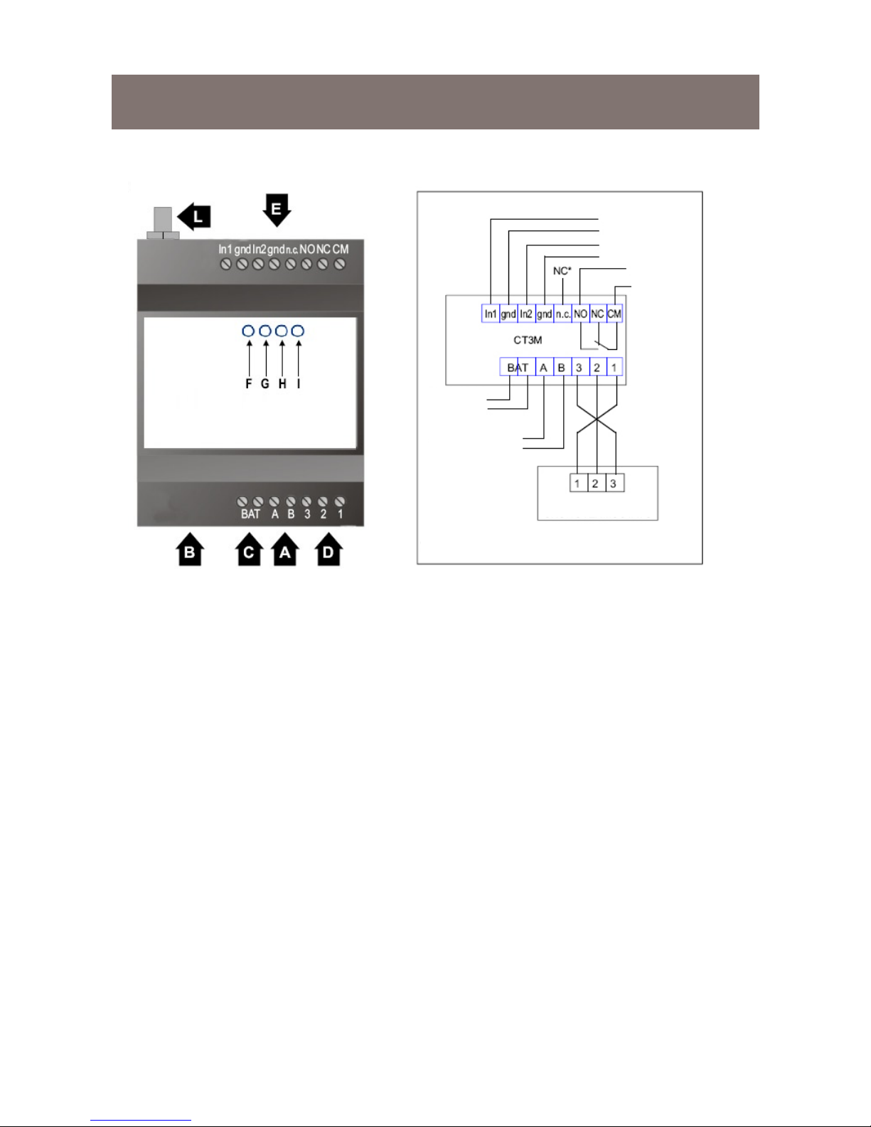
Front view .................................................................................10
Wiring diagram .........................................................................10
SIM card ..................................................................................12
CT3MA connection to chronostats ...........................................13
Interface description .................................................................13
Connection description ..................................................................17
Input contacts ...........................................................................17

5
Table of Contents
Output contacts ............................................................ 18
Operating state / LED ........................................................ 19
Remote management ........................................................ 20
Using the SIM card ....................................................... 20
Standby ........................................................................ 20
Sending an alarm ......................................................... 20
Output status led .......................................................... 21
SMS Service Centre ..................................................... 21
Setting the SMS Services Centre ................................. 21
SMS commands ........................................................... 21
Chronostat commands ................................................. 21
Alarm commands ......................................................... 22
Alarm commands ......................................................... 23
Relay commands ......................................................... 23
Status response ........................................................... 24
Maintenance / Circuit diagram ........................................... 25

6
Product description
CT3MA is a GSM terminal suitable for remote control of heating sy-
stems, specially when no xed telephone line is provided.
CT3MA also enables to control two remote inputs and one output.
Communication is implemented via a mobile phone and the GSM
modem of the device using SMS messages.
CT3MA characteristics, functions and interfaces are described on
next pages.

7
Product description
Operation
When CT3MA is connected to a Fantini Cosmi chronostat model
C46A, C55-56, C51-52-53-54, C75CT-76CT, CH15X, via SMS mes-
sages it enables to read the chronostat status (ambient temperature
measured, programme set, etc.) to modify the set programme and to
change certain thermoregulation parameters (only for CH15X).
CT3MA can automatically send a SMS message to the phone num-
ber stored inside it when an alarm conditions occurs (due to contact
clo-sing/opening).
NOTE: different alarms can be controlled by setting them parallel
with each other.
External antenna
Connect dual band antenna (GSM900/1800) to RF interface avail-
able on CT3MAA model. Connection is obtained by connecting the
antenna to the SMA/F connector set on the top of the device.
Immunity against interference
Provide suitable protections against fast transients if the cable is lon-
ger than 3m

8
CHARACTERISTICS
Specications
Quad band
Output power:
Class 4 (2W) for
Class 1 (1W) for
Sensitivity
Power voltage:
Consumption
Operating temperature
* reduced sensitivity
Rear wall mounting on EN 50022 rail, 4 modules
Approximate weight:
Protection EN 60529: IP40
(if installed properly)
Contact rating
Voltage-free contacts
Connections
Power supply connector
Input / Output connector
Accessories
Power supply unit / battery charger N70A
CTI46 - CTI5 - CTI5X connection interfaces for Fantini
Cosmi chronostats (See paragraph “INSTALLATION”,
pages 13 to 16)
Lead battery, rechargeable, external
Long-life lithium buffer battery, not rechargeable

9
Installation
Package contents
CT3MA Telecontrol
External antenna
Instruction manual
Installation and safety information
CT3MA shall be installed by qualied personnel only.
If power supply is provided by an external unit, the latter shall comply
with SELV1 circuits specications according to EN60950.
If batteries are used, follow the specic instructions.
The cable between the CT3MA and the power source shall not be
longer than 3 m.
Power supply shall not be shared with other devices.
Mounting
CT3MA can be quickly tted to EN 50022 standard rails, rear wall
moun-ting.
External antenna
Connect the antenna provided as standard before powering the
device. To operate regularly the antenna shall not be shielded by
metallic walls.
1 Safety Extremely Low Voltage

10
Installation
A. Power supply input
B. SIM card slot (remove lower cover)
C. Lithium battery connections (see “Accessories” on page 8)
D. Chronostat connections
E. Input and output connections
F. GSM network status indicator LED
G. Input1 status indicator LED (alarm1)
H. Input2 status indicator LED (alarm2)
I. Relay status indicator LED
L. External antenna connector
IMPORTANT NOTE: Wiring and electric connections shall be all im-
plemented before powering the CT3MA. More particularly, if connec-
tion to a Fantini Cosmi chronostat is required, connect the chronostat
to the GSM activator before switching the activator on, otherwise the
CT3MA may not recognise the connected device.
Front view Wiring diagram
ALARM INDICA-
TIONS
ELECTRIC
CONSU-
MERS
EXTERNAL
BATTERY
POWER SUPPLY
*NOTE: NC = NOT CONNECTED
CHRONOSTAT
INTERFACE

11
Installation
CT3MA makes available the following connections:
Power supply terminals
Input terminals
Output terminals
External battery terminals
Chronostat interface terminals
SIM card slot
Power supply
CT3MA receives power supply from terminals A and B, on
the bottom left of the container.
Power supply voltage shall be between 10 and 20 Vac/
Vdc.
Use N70A power supply unit or another with similar
characteristics.
The cable shall not be longer than 3 m.
Protection for polarity inversion
CT3MA can be powered indifferently with alternate cur-
rent or direct current, regardless of the polarity.
Fuses
If external protections are installed, set 1.5 A rapid fuse
on the power supply unit line.

12
Installation
SIM card
The SIM card housing ts for 3V SIM cards suitable for use with
CT3MA according to GSM 11.12 phase 2+.
Fit the SIM card into the housing to start CT3MA operation.
1. Disconnect CT3MA from power supply unit and release the lower
cover by means of a screwdriver or equivalent tool.
2. Move the cover upwards.
3. Raise the SIM card holder, insert into the slot the SIM card with the
chamfered edge positioned as shown in the gure. Lower the SIM
card holder and push it down to lock it in position.

13
Installation
CT3MA connection to chronostats
To connect CT3MA to a Fantini Cosmi chronostat, use the connec-
tion interfaces provided for the purpose (for CH15X chronostats refer
to the relevant user’s manual).
The following pages describe the different available interfaces (not
included in this package) and the proper connections to be per-
formed.
Interface description
CTI46 CONNECTION INTERFACE FOR C46A CHRONOSTAT
Replace the original C46A chronostat base with the CTI46 interface
base.
Use 3 x 0.5 mm2 cable, max. length: 20 metres
Connect CTI46 electronic card terminal board according to the wiring
diagram shown below (interface terminals 1 - 2 - 3 with the corre-
sponding CT3MA terminals 1 -2 -3).
ALARM INDICA-
TIONS
ELECTRIC
CONSU-
MERS
EXTERNAL
BATTERY
POWER SUPPLY
*NOTE: NC = NOT CONNECTED
CTI46 INTERFACE
C46A CHRONOSTAT

14
Installation
CTI5 CONNECTION INTERFACE FOR C55 - C56 CHRONOSTATS
CTI5 interface connection to C55 or C56 chronostat.
Remove the chronostat body from the base.
Open the two knockdown slots on the chronostat body as shown in
the gure.
Snap-fasten the interface onto the chronostat. Take care to t pro-
perly the female connector of the module onto the chronostat feet.
Fasten the thereby obtained unit onto the chronostat base.
Electric connections
If xed installation with wiring under chase is required or if the cable
provided with jack plug is short, use another cable 3 x 0.5 mm2 with
20 m max. length. Connect one end to terminals 1 -2 - 3 of the ad-
ditional module and weld the jack plug as shown in the diagram. In
case of xed installation only: open the knockdown area on the base
to friendly connect cables to terminal board.
Open the knockdown area
on the C55 / C56 base (for
xed installation only)
Open the two knockdown
slots on the chronostat
Snap-fasten the module,
take care to t the con-
nector properly
*NOTE: NC = NOT
CONECTED
ALARM
INDICA-
TIONS
ELEC-
TRIC
CONSU-
MERS
EXTERNAL
BATTERY
POWER SUPPLY
CTI5 INTERFACE
C55 - C56 CHRO-
NOSTAT
Terminal
board
Jack plug

15
Installation
CTI5X CONNECTION INTERFACE FOR C51 - C52 - C53 - C54
CHRONOSTATS
Remove the chronostat from the relevant housing and snap-fasten
CTI5X interface as shown in the gure.
Carry out the required connections.
Connect CTI5X terminal board according to the diagram shown be-
low (interface terminals 1 - 2 - 3 with the corresponding CT3MA ter-
minals 1 -2 -3).
Use 3 x 0.5 mm2 cable, max. length: 20 metres.
ALARM INDICATIONS
ELECTRIC CON-
SUMERS
EXTERNAL
BATTERY
POWER SUPPLY
*NOTE: NC = NOT CONNECTED
CTI5X INTERFACE
C51 - C52 - C53
- C54 CHRO-
NOSTAT

16
Installation
CONNECTION TO C75CT AND C76CT CHRONOSTATS
To connect C75CT (or C76CT) to CT3MA no interface is required;
just disconnect the chronostat from the base and connect CT3MA to
the terminal board set on the back of the chronostat (see the gure)
according to the wiring diagram shown below.
ALARM INDICATIONS
ELECTRIC CONSUMERS
EXTERNAL
BATTERY
POWER SUPPLY
CONNECTION TO
C75CT AND C76CT
CHRONOSTATS
*NOTE: NC = NOT CONNECTED Terminal board

17
Connection description
Input contacts
CT3MA can be connected to two external clean contacts.
Contacts power supply is provided by CT3MA.
Use mechanical or electromechanical contacts suitable for use with
40Vmin / 20mAmin dc.
Polarity
When using electronic switches, terminals In-1 and In-2 are positive
terminals whereas GND is the reference.
Anti-rebound
To prevent false operations, contacts ate considered closed or open
only after 1 second of stable condition.
Connection
Immunity against interference
The cable shall not be longer than 3 m.

18
Connection description
Output contacts
CT3MA is tted with SPDT contact from relay.
Contact characteristics
Rated voltage: 250 Vac /100 Vdc
Max. switching current 4(2)A
Insulation: 250 V (IEC664 / VDE 0110 - cat. III / C)
Cadmium-free contacts
Protection against overvoltages
Suitable protections against overvoltages on output contacts are
recommended in the event of heavy duty.
Connection

19
Operating state / LED
The LED (F, see page 10), on the front panel shows the different
CT3MA operating states:
Operating state LED
- Not powered OFF
- Network search ON (fast ashing)*
- Standby (recorded in the
network)
SLOW FLASHING
* Network search usually requires a few seconds after power on.
If the led stays on ashing check for proper SIM card tting.
The LEDs (G - H - I) on the front panel in addition to show INPUT and
OUTPUT status indications show also the following CT3MA operat-
ing states:
Operating state LED
-No SIM card Fast ashing
- Field intensity measurement G+H+I according to eld
intensity#
#Field intensity is measured only at power on and during the rst
seven minutes after device recording on the GSM network. Field
measurement can be stopped by sending whatever command via
SMS message or waiting for seven minutes. G, H and I LEDs indi-
cate eld intensity as follows:
Very low intensity: G Off, H Off and I Off
Low intensity: G On ashing, H Off and I Off
Good intensity: G On ashing, H On ashing and I Off
High intensity: G On ashing, H On ashing and I On ashing
If GSM signal intensity level is lower than -109dBm, CT3MA may not
work properly.

20
Remote management
Using the SIM card
Before using the SIM card, we recommend that you test it in a mobile
phone to see if it’s working.
Particularly:
- Check that no PIN code has been set. If so, exclude it.
- Check the remaining credit
- Send a SMS message and check if it arrives.
Switching oncensione
After switching the device on, SMS messages not yet delivered or
sent during the rst instants of operation will be cancelled without
being performed.
Standby
In Standby status, CT3MA is recorded in the GSM network and it is
ready to send and to receive SMS messages.
Synchronisation with the GSM network is obtained through short and
continuous transmissions.
CT3MA consumption in this status depends on whether the network
is avai-lable or not.
Sending an alarm
When input contacts are closed, the corresponding LEDs (G and H)
will turn on and CT3MA will send to stored numbers the following
message: “Input1 ON!” or “Input2 ON!”.
Alarm sending condition can however be set as follows:
Send alarm at contact closing
Send alarm at contact opening
Send alarm at both contact opening and closing
NOTE: Alarm is only sent if there is at least one mobile phone num-
ber stored, to which the alarm message can be sent. To cancel a
stored phone number, to customize the alarm message or to select
the alarm sending condition, follow the procedure described in para-
graph “ Alarm commands” on page 22.
Table of contents
Popular Remote Control manuals by other brands

WolfVision
WolfVision VZ-8neo instructions

Magnavox
Magnavox RG57H/BG manual

Truth Hardware
Truth Hardware Sentry II WLS installation instructions

Cardin Elettronica
Cardin Elettronica FM Set up and user instructions

Novus
Novus Attenzia space XT Translation of the original operating instructions

Daikin
Daikin FTXN-L9 operating manual