manuals.online logo
Brands
  1. Home
  2. •
  3. Brands
  4. •
  5. Faraday
  6. •
  7. Fire Alarm
  8. •
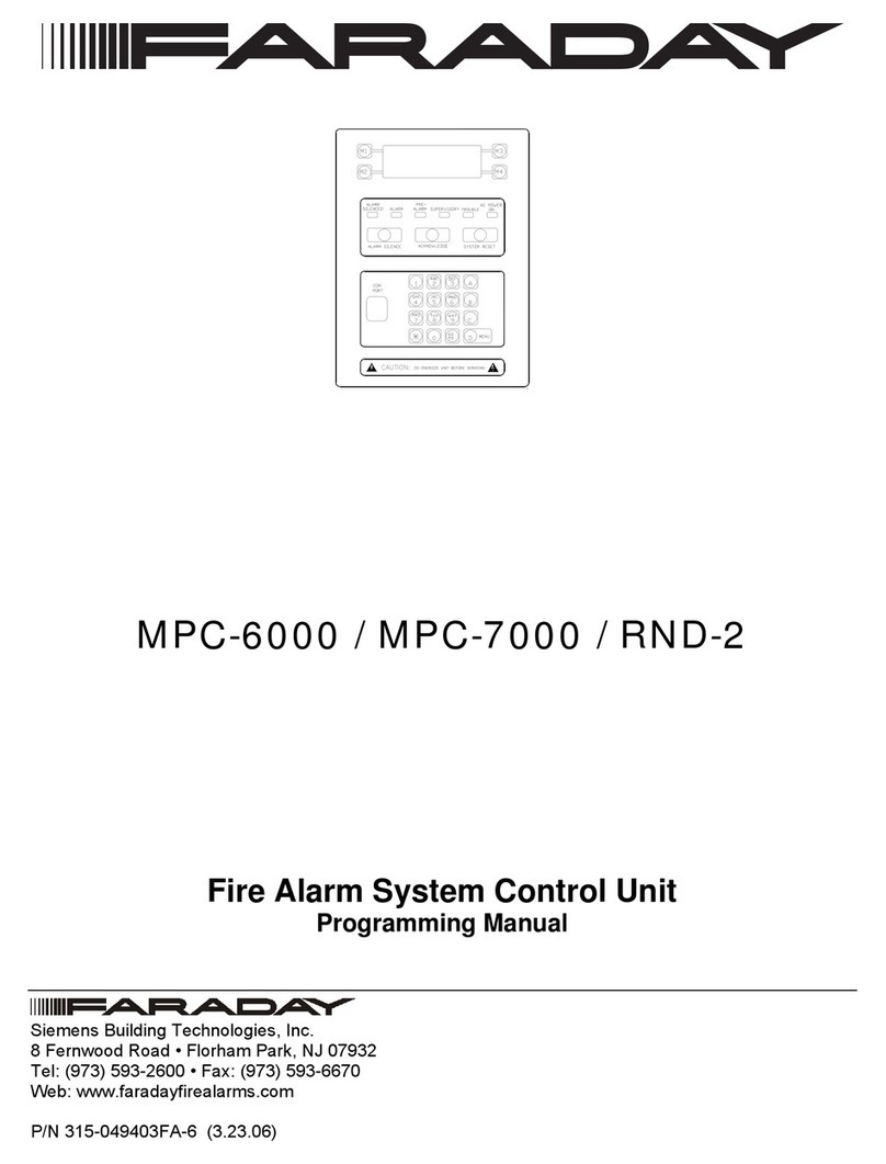
  9. Faraday RND-2 User manual

Faraday RND-2 User manual

INSTALLATION INSTRUCTIONS FOR
MPC-6000, MPC-7000 AND RND-2 DISPLAY BOARDS
Installation is to be done by qualified personnel who
have thoroughly read and understood this instruction
sheet.
Step 1.) Upload the panel configuration to the CIS-4 software.
Step 2.) Disconnect BATTERY and AC prior to working on
equipment.
Step 3.) Remove cable connection from the keypad on the
Inner Front Plate to connector J3 on the Display
Board (P/N MPC(6/7)-DB, MPC6-DB2, RND2-DB or
RND2-DB2).
Step 4.) Remove the cable assembly (P/N 555-446055) from
connector J1 of the Display Board (P/N MPC(6/7)-
DB, MPC6-DB2, RND2-DB or RND2-DB2).
Step 5.) Remove the Display Board (P/N MPC(6/7)-DB,
MPC6-DB2, RND2-DB or RND2-DB2) from Inner
Front Plate Assembly by removing the four screws.
Place the screws to one side. Refer to Figure 1.
PLATE
906-220604 (4)
#6-32 x 1/4 SCREW
MPC-6000
ASS'Y
J3 - Keypad
Connection
Board
Display
to Main
J1 - Connection
Board
MPC-7000
showing Display
Board and Keypad
to Front Plate Ass'y
Board attached
showing Display
being attached
to Front Plate Ass'y
Figure 1
Display Board Removal/Installation
P/N 315-050139FA-0
Siemens Building Technologies, Inc.
8 Fernwood Road Phone: (973) 593-2600
Florham Park, New Jersey 07932 Fax: (973) 593-6670
Web: www.faradayfirealarms.com
Step 6.) If replacing an RND-2 display board, transfer the
panel firmware IC (U4, located in the socket at the
lower right corner of the board as shown in Figure 2)
from the old board to the new one by following the
steps listed below.
U4
J2
R13
S1
U21
U2
U5
U6
J9
U12
J1
J3
Replace U4
U4
Figure 2
Replacing U4 on RND-2
a. Note where and how the IC is positioned.
b. Use a DIP extraction tool to remove U4 from its
socket on the new display board and then discard this
IC. If an extraction tool is not available, a short, thin
blade screwdriver may be used.
c. Remove U4 from the old display board. Insert
this IC into the proper socket on the new display
board. Press down firmly to seat the IC properly in
the socket.
CAUTION:
Make sure the "U" cut in the new IC is positioned as it
was in the old IC (if appropriate). Check that the IC is
properly seated in the socket and that all the IC pins
are properly aligned.
2
Step 7.) Reattach the cable connection from the keypad on the
Inner Front Plate to connector J3 on the Display Board
(P/N MPC(6/7)-DB, MPC6-DB2, RND2-DB or RND2-DB2).
a. Keypad with releasing application LEDs for
MPC-6000 only
Align the keypad connector (P/N 215-649557FA) to J3
of the MPC6-DB2 as shown below. Insert the keypad
connector to the J3 header with pin 1 of J3 properly
aligned with the keypad connector until it is a tight fit.
(Refer to Figure 3.)
J3
J1
26-pin ribbon cable
connected to the
Main Board
Keyboard with
Releasing LEDs
connector
(P/N 215-649557FA)
Figure 3
Keypad with Releasing Application LEDs
b. Keypad without releasing application LEDs
Align the keypad connector (P/N 215-649113FA) to J3
of the MPC6-DB2 as shown in Figure 4. Insert the
keypad connector to the J3 header with pin 1 of J3
properly aligned with the keypad connector until it is a
tight fit. Verify that pins 19-22 (last four pins) of J3
are not connected to the keypad.
LCD Contrast A djust
Backside of MPC6-DB2
LCD location
1
J3
J1
26-pin ribbon cable
connected to the
Main Board
Keyboard with no
Releasing LEDs
connector
(P/N 215-649113FA)
Figure 4
Keypad without Releasing Application LEDs
Step 8.) Secure Display Board (P/N MPC(6/7)-DB, MPC6-
DB2, RND2-DB or RND2-DB2) to Inner Front Plate
Assembly using the four screws removed in Step 5.
Refer to Figure 1.
Step 9.) Plug the Cable Assembly (P/N 555-446055) into
connector J1 of the Display Board (P/N MPC(6/7)-DB,
MPC6-DB2, RND2-DB or RND2-DB2) and to
connector J11 of the Main Board (P/N MPC6-MB,
MPC6-MB2 or MPC7-MB).
Step 10.) Apply power to system.
Step 11.) Download the panel configuration from the CIS-4 to
the panel and swap.
a. We recommend copying the primary configuration
to the secondary after swapping.
P/N 315-050139FA-0

This manual suits for next models

2

Other Faraday Fire Alarm manuals

Faraday 15220A User manual

Faraday

Faraday 15220A User manual

Faraday MPC-6000 Owner's manual

Faraday

Faraday MPC-6000 Owner's manual

Faraday FireWatch 400 User manual

Faraday

Faraday FireWatch 400 User manual

Faraday LW401 Instruction Manual

Faraday

Faraday LW401 Instruction Manual

Faraday MPC-6000 Owner's manual

Faraday

Faraday MPC-6000 Owner's manual

Popular Fire Alarm manuals by other brands

Aritech 1200C user manual

Aritech

Aritech 1200C user manual

Panasonic EBL128 user manual

Panasonic

Panasonic EBL128 user manual

Jade Bird JBE-2100 manual

Jade Bird

Jade Bird JBE-2100 manual

olympia electronics BSR-1001 manual

olympia electronics

olympia electronics BSR-1001 manual

Honeywell SMX-AUS installation guide

Honeywell

Honeywell SMX-AUS installation guide

E2S D2xC2LD3 instruction manual

E2S

E2S D2xC2LD3 instruction manual

Panasonic MEW01349 operating instructions

Panasonic

Panasonic MEW01349 operating instructions

Global Fire Equipment ZEOS-C quick start guide

Global Fire Equipment

Global Fire Equipment ZEOS-C quick start guide

Channel Safety Systems Rapidfire instruction manual

Channel Safety Systems

Channel Safety Systems Rapidfire instruction manual

Interlogix ESL installation instructions

Interlogix

Interlogix ESL installation instructions

Autronica BS-310 Operator's handbook

Autronica

Autronica BS-310 Operator's handbook

Secutron MMX-2009-12NDS user guide

Secutron

Secutron MMX-2009-12NDS user guide

Honeywell Silent Knight SK318PT Installation and operation guide

Honeywell

Honeywell Silent Knight SK318PT Installation and operation guide

Cooper Notification ST-C installation instructions

Cooper Notification

Cooper Notification ST-C installation instructions

System Sensor PS12/24ADA Series Installation and maintenance instructions

System Sensor

System Sensor PS12/24ADA Series Installation and maintenance instructions

LY International Electronics M-9000 Series user manual

LY International Electronics

LY International Electronics M-9000 Series user manual

EMS FIRECELL quick start guide

EMS

EMS FIRECELL quick start guide

Silent Call Communications FA41-MC Installation and operating instructions

Silent Call Communications

Silent Call Communications FA41-MC Installation and operating instructions

manuals.online logo
manuals.online logoBrands
  • About & Mission
  • Contact us
  • Privacy Policy
  • Terms and Conditions

Copyright 2025 Manuals.Online. All Rights Reserved.