Faraday MPC-6000 Owner's manual

FARADAY
8 Fernwood Road
Florham Park, New Jersey 07932
P/N 315-049403FA-1
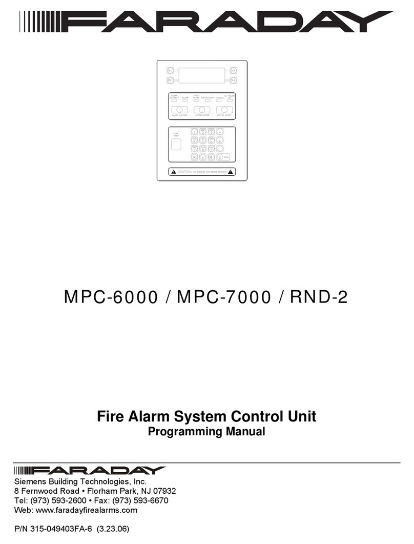
MPC-6000 / MPC-7000
Fire Alarm System Control Unit
Programming Manual


Table Of Contents
Introduction............................................................................................................................. 1
The Access levels..................................................................................................................... 1
User Level ..............................................................................................................1
Maintenance Level..................................................................................................2
Technician Level.....................................................................................................2
The Operator Interface ..........................................................................................................3
Interface for User and Maintenance Levels ............................................................3
Interface for the Technician Level...........................................................................4
Entering Alphanumeric Characters.........................................................................5
QUICK START....................................................................................................................... 6
Automatic programming of a new system...............................................................6
Manual programming of a system ..........................................................................7
Programming Concepts.......................................................................................................... 9
Program Memory....................................................................................................9
The programming model of the system ................................................................10
Automatic Programming .......................................................................................11
User Level.............................................................................................................................. 14
Activating a General Alarm ...................................................................................14
Activating an Alert.................................................................................................14
Activating a Drill....................................................................................................14
Activating a Recall ................................................................................................15
Performing a Lamp Test .......................................................................................15
Viewing the Event History.....................................................................................15
Accessing Maintenance Functions .......................................................................15
Accessing Technician Functions ..........................................................................16
Maintenance Level................................................................................................................ 17
Enabling/Disabling Devices ..................................................................................17
Enabling/Disabling Input Groups ..........................................................................17
Enabling/Disabling Applications............................................................................17
Enabling/Disabling the Output Zones ...................................................................17
Enabling/Disabling NACs......................................................................................18
Enabling/Disabling City Tie...................................................................................18
Enabling/Disabling the DACT ...............................................................................18
Enabling/Disabling the Status Relays...................................................................18
Changing the Maintenance Password ..................................................................19
Setting the Time....................................................................................................19
Setting the Time Format .......................................................................................19
Enabling Daylight Savings Time Adjustment ........................................................19
Setting the Date....................................................................................................19

Setting the Date Format........................................................................................19
Clearing the History ..............................................................................................20
Printing the History ...............................................................................................20
Printing the Sensitivity Levels ...............................................................................20
Editing the System Label ......................................................................................20
Editing the Device Labels .....................................................................................20
Starting Quick Test ...............................................................................................21
Configuring NAC sound time for Quick Test .........................................................21
Configuring the printer during Quick Test .............................................................21
Programming a Device .........................................................................................21
Technician Level ................................................................................................................... 22
Editing a Device Configuration .............................................................................22
Editing an Input Group Configuration....................................................................24
Editing a System Group Configuration..................................................................25
Configuring the NACs ...........................................................................................25
Configuring the Remote Relays (SRUs) ...............................................................26
Configuring the Remote LEDs (SLUs) ..................................................................26
Configuring the Remote LCDs (RDCs) .................................................................27
Installing the DACT...............................................................................................27
Configuring the DACT Accounts...........................................................................27
Setting System Timers..........................................................................................27
Configuring the City Tie Activation........................................................................28
Setting Trouble Ack Required...............................................................................28
Setting the System Reporting Type ......................................................................28
Copying the Primary to the Backup ......................................................................28
Printing the Primary/Backup Configuration ...........................................................29
Validating the Backup Configuration.....................................................................29
Activating the Backup ...........................................................................................29
Hard Reset ...........................................................................................................29
Changing Access Passwords ...............................................................................29
Exiting the Technician Level .................................................................................30
APPENDIX A: GLOSSARY................................................................................................ 31
APPENDIX B: REFERENCES........................................................................................... 34

MPC 6000/7000 PROGRAMMING MANUAL
1
Introduction
The MPC 6000/7000 Fire Alarm Control Panels are completely field programmable.
Although programming requires no special software skills, a thorough working
knowledge of Fire Alarm Control Panels and devices is assumed. There are two
ways to program an MPC 6000/7000 fire alarm system control unit:
1. Auto Program. Using Auto Program will quickly configure the FACP in a General
Alarm configuration.
2. Manual Program. Editing the program manually using the keypad.
Both methods require that the Technician password be entered so that the
Technician functions may be accessed. Jump to the Quick Start section if you need
to get a system up and running quickly.
The Access levels
The MPC 6000/7000 system has three functional levels as follows:
•
User Level, no password is required to access these functions.
•
Maintenance Level, accessed using the Maintenance password, allows access to the
maintenance menu functions.
•
Technician Level, accessed using the Technician password, allows access to trained
technician menu functions.
User Level
The User level functions accessible to the system user are protected from
unauthorized use by the lock on the front of the cabinet. Pressing the Menu button
on the lower right of the operator interface accesses the user functions. The
functions available to the User are as follows:
•
Activate a General Alarm
•
Activate an Alert event
•
Activate a Recall event
•
Activate a Lamp Test
•
Activate a Drill
•
View event history
•
Go to Maintenance Level (with the password)
•
Go to Technician Level (with the password)
•
Log on to a remote panel

MPC 6000/7000 PROGRAMMING MANUAL
2
Maintenance Level
The Maintenance level is accessed via the User Menu and the correct password.
The functions accessible in the maintenance level are as follows:
•
Enable or disable devices, outputs, groups, zones, status relays and option modules
•
Configure and run a Quick Test
•
Print History
•
Print Detector Levels
•
Edit Device and system labels
•
Set the system time and date
•
Change the Maintenance Level access password
•
Program a device
•
Clear event history
•
Enabling or disabling application
Technician Level
The Technician level is accessed via the User Menu and entering the correct
password. The functions accessible in the technician level are as follows:
•
Configure devices, outputs, groups, zones and option modules
•
Set System parameters (i.e., automatic silence, alarm silence inhibit, reset inhibit, etc.)
•
Configure MPCnet network options (Future use)
•
Configure bell codes
•
Validate the backup configuration
•
Swap the primary and backup configuration
•
Copy the primary to the backup configuration
•
Print the primary and backup configuration
•
Change the Technician Level access password

MPC 6000/7000 PROGRAMMING MANUAL
3
The Operator Interface
Interface for User and Maintenance Levels
The operator interface for configuring and programming the MPC 6000/7000 uses
the 4 line by 20 character LCD display, the M1 through M4 buttons on the left and
right of the display and sixteen push buttons at the bottom of the interface. User
Level and Maintenance Level utilize the LCD display and the four buttons (two on
each side of the display) to navigate and alter the basic operation of the panel. The
display will show messages in the four corners of the display that will be adjacent to
the four buttons M1 through M4. The message on the display adjacent to the button
indicates the action that will occur when the button is pressed. Therefore pressing
M1 will cause the function labeled as “Menu 1” to be pressed.
M1 M3
M2 M4
For example, in the following figure, menu item 1 (Lamp Test) is described as having
an Action of ‘Run Lamp Test’. If the button next to Lamp Test is depressed, Lamp
Test will be performed. Menu item 2 (View History) will cause the first event in the
event history to be displayed on the screen.
Action: Run Lamp Returns to the top of
the list or to the level
up
Will display panel go to the next screen
History
Lamp Test Esc
View
History More
Menu 1 Menu 3
Menu 2 Menu 4

MPC 6000/7000 PROGRAMMING MANUAL
4
Interface for the Technician Level
When the Technician Level is accessed using the password, the LCD display and
the keypad are used to program the panel, and to view the programming if desired.
The display acts as a menu and the keypad allows the user to navigate through the
menu of functions and change or print the programming. The following figure
describes the navigation used in this context:
A-esc: will backup to previous screen
B-fn1: will perform function 1
C-fn2: will perform function 2
D-Nxt: will step to the next screen
Each menu item is associated with "A", "B", "C", or "D" buttons on the keypad.
Pressing one of these keys will cause the panel to go to the function associated with
the button.
For example
A-Esc, will backup to previous screen
B-+20 Jumps ahead 20 devices
C-mor shows further options in list
D-+1, Jumps ahead 1
Aesc
Bfn1
Cfn2
Dnxt
ZNxxx P Aesc
ZoneType:PRESIG B+20
Timer:___ Sec Cmor
To Zone #:___ D +1

MPC 6000/7000 PROGRAMMING MANUAL
5
Entering Alphanumeric Characters
Entry of alphanumeric data using the keypad is as follows:
•
Each character is entered using a two-keystroke sequence on the keypad.
•
Numerals are entered using the sequence 0x, where x is the numeral to be entered.
•
Letters are entered using 1x, 2x, 3x, and 4x sequences, based on the letters appearing
above the numbers on the keypad, where the first digit (1, 2, 3 or 4) is the position of
the letter and the second digit is the numerical key on which that letter appears. For
example, to enter the letter “A” use the sequence “12”. To enter the letter “N” use the
sequence “26”. Exceptions are the letters “Q” and “Z” which do not appear on the
keypad. The letter "Q" is entered using the sequence "27", as though "Q" appears on
the "7" between "P" and "R". The letter "R" is entered as "37" and "S" as "47". Similarly,
"Z" is entered as "49", as though "Z" appears on the "9" key. Punctuation marks are
entered using 5x, 6x, 7x, and 8x sequences, as shown below:
CHARACTER SEQUENCE CHARACTER SEQUENCE
<space> 50 > 70
! 51 ? 71
" 52 @ 72
# 53 [ 73
$ 54 ¥ 74
% 55 ] 75
& 56 ^ 76
´ 57 _ 77
( 58 ` 78
) 59 { 79
* 60 | 80
+ 61 } 81
, 62 →82
- 63 ¦ 83
. 64
/ 65
: 66
; 67
< 68
= 69
•
Insert and overwrite modes can be toggled using the "
C
" key.
•
Entering the same letter into a position in overwrite mode will change the case of the
letter (i.e., if a position contains the letter "f", and the user enters "33" in overwrite
mode, the "f" will change to "F").
•
A character may be deleted by pressing the “
9
” key.
•
Pressing the * key will move the cursor back one space; pressing the # key will move
the cursor forward one space.

MPC 6000/7000 PROGRAMMING MANUAL
6
QUICK START
Automatic programming of a new system
This is the quickest way to get a system operational. After all of the devices,
notification appliances and option modules have been programmed and installed,
check all wiring for grounds, shorts and opens. Connect SLUs, SRUs, NACs and
any other field wiring to the panel.
Automatic programming is selected from the Technician Level. Below are the steps
to access the Technician Level.
Step Action Description
1 Press “Menu” and then press “More” until
the option “Tech. Level” is displayed.
2 Press “Tech. Level”. The display will show the entry
screen for the technician level
access password.
3 Enter the password on the keypad. The
default is “0 1 2 3 4 5”.
The password will appear in the
screen.
4 Press “Enter” or “D”. The display will show the starting
screen of the Technician Level.
Once the Technician Level has been accessed, following are the steps to activate
the autoprogram function.
Step Action Description
1 Select “Edit” by pressing “4”. The display will show the first
screen of the Edit functions with
“Auto Pgm” as one of the options.
2 Select “Autoprgm” by pressing “7”. The display will show the
Autoprgm screen.
3 Start the autoprogram by pressing the “D”
key.
The display will show all of the
addresses being checked as the
auto program is performed. This
could take several minutes. As
each new device is found, the
display will allow the installer to
chose whether to include the found
device. When the autoprogram is
finished, the screen will return to
the Edit options.

MPC 6000/7000 PROGRAMMING MANUAL
7
Note NOTE #1: The backup configuration will now contain a configuration as follows:
all input points in group #241 (General Alarm). The General Alarm System
group is pre-programmed to activate all output zones. Any Remote LCD
displays that were connected at the time of Auto Program will also be activated.
However remote relay (SRUs) and remote Led modules (SLUs) will not be
detected and so will not be in the configuration.
4 At the EDIT BACKUP screen, press “A”
and escape back to TECH LEVEL
screen.
The display will show the starting
technician menu.
5 Use “C” to get to the next set of functions
and select “validate”.
This will cause the data in the
backup configuration to be
checked. Correct any errors found
before continuing.
6 Press the “*” key followed by the "C" key
when prompted. This action will cause the
auto programmed configuration to be
swapped into the primary memory and the
panel will be restarted. (You now have as
the primary configuration the result of the
Auto Program. In other words, a General
Alarm system.)
The panel will reset and reinitialize.
Manual programming of a system
Manual programming is a much more involved operation and requires knowledge of
the operation of the system before proceeding. The basic steps to programming a
system configuration are as follows:
Step Number
Configure Description
1 System configuration Set a number of overall system parameters.
2 Loops Set up each loop, one in the case of the 6000
and (up to) four in the case of the 7000.
3 Input groups/system
groups
Set up the behavior of the input group or system
groups--the bell codes it will activate and the
output zones that will be activated by this input
group. Note that an input group must be
configured to activate an output group to cause
any output activations.
4 Devices Set the address and other parameters for each
of the devices that will be installed into the
system. Configure the input group of each
device. Note that devices must be connected to
an input group for any output to be activated. If
the panel is networked, also setup the network
group that this device will activate.

MPC 6000/7000 PROGRAMMING MANUAL
8
5 Notifications
appliance circuits
Configure the behavior of the NACs and the
output zone that will activate each NAC. Note
that a NAC must be configured as connected to
an output zone or it will not activate.
Optional 6 LCD Annunciators If there are any remote LCD displays, set
whether installed.
Optional 7 Remote LEDs If there are any remote LED modules, configure
each of the remote LEDs. Select the Output
zone that will activate the LED.
Optional 8 Remote Relays If there are any remote Relay modules,
configure each of the remote Relays. Note that
the Relays must be connected to an Output
Zone in order to activate.
Optional 9 DACT line/DACT
account
If a dialer is installed, configure the line and
account data.
10 Validate Run the validate and fix any errors that are
reported.
11 Activate Swap the backup configuration with the primary
configuration.

MPC 6000/7000 PROGRAMMING MANUAL
9
Programming Concepts
Program Memory
The program memory consists of two components, the PRIMARY (active)
configuration and the BACKUP (editable) configuration. The primary configuration is
the active (running) configuration that determines the current function of the FACP.
The backup configuration is the configuration that is edited to make changes or
additions to the existing active panel program. This allows the program to be edited
while the FACP operates normally.
Before the backup configuration is activated, it first must be validated to make sure
that the configuration follows the installation rules. The validation process ensures
no values or operating parameters are out of limits.
When the edited configuration is activated, all changes are implemented at once by
swapping the primary and backup configurations. The backup configuration
becomes the primary (running) configuration and the configuration that was running
becomes the backup configuration.
NOTE: At this point it is advisable to copy the primary configuration to the backup so
that both configurations are identical. There is a copy feature that allows the
operator to copy the primary configuration to the backup.

MPC 6000/7000 PROGRAMMING MANUAL
10
The programming model of the system
The following diagram shows the programming model of the MPC-6000 and
MPC-7000 systems.
22
1
32
12
T
T
T
T
Input group
Output Zones
up to 255
An input group can
activate any or all
Output Zones.
NACs and Audible
bases can connect to
one and only one output Zone.
Input devices
can belong to
one local input
group.
Monitor modules and detector
base relays can connect to one
and only one output zone.
Remote relays and remote
LEDs connect to output zones.
Each input device can be
configured for type of
operation, i.e.,
alarm, manual pull,
waterflow, sil waterflow,
trouble, supervisory, non-
fire, panel reset, alarm
silence, acknowledge.
Each relay can
have its output
behavior
configured, i.e.,
non-silencable,
trouble active,
supervisory, pre-
alarm, silenceable,
trouble silence,
supervisory
silence.
Each LED and remote
relay can have its
output behavior
configured, i.e.,
Alarm active, trouble,
supervisory, pre-alarm.
GC
GC
GC
GC
GC
The input group may
be configured for
different activation, i.e.,
none, fire zone, cross
zone, PAS, pre signal,
wildcard.
Each output can be set
for the control behavior,
i.e., non-silencable,
trouble active,
supervisory, pre-alarm,
silenceable, trouble
silence, supervisory
silence.
The MPC 6000 and 7000 programming model
Can set various
behaviors depending on
the type of system
zone. (Mainly output
coding.)
System groups: general alarm
drill
recall
alert
trouble
quick test
up to 240 input
groups

MPC 6000/7000 PROGRAMMING MANUAL
11
The basic concept is that loop devices are configured and grouped into input groups.
The input groups are set to have a certain behavior and activate output zones. The
output devices―whether relay bases, audible bases, NACs, serial LEDs or Serial
relays―are configured and connected to Output Zones.
Automatic Programming
Auto-program can be done with a new, non-configured control unit or to augment an
existing configuration. Augmenting an existing program adds new points but leaves
previously programmed points unaffected. Discrepancies in the configuration will be
presented individually for acceptance. Again, auto program writes information into
the backup and must be validated before becoming the primary operating
configuration.
Auto Program will recognize the types of devices connected and will set up different
parameters depending on the devices it finds. The following tables show the settings
for the different device types.
Smoke and thermal detectors
Parameter Description
Label Generic label identifying the detector by loop number and address.
Application If FireSmart detectors are found, the application will not be changed in the
device. Factory default is none.
Sensitivity The sensitivity of the detectors will be left as found. The factory default is
3.00%.
ROR Rate of rise will be off.
Led off LED will be defaulted to ON.
Pre-alarm Pre-alarm will be off.
Verification Verification will be as found in the detector.
Input Usage The input usage will be set to Alarm.
Input Group All detectors will be set to input group 241.
Network Group This will not be set and will need to be set manually. (Future use)
Relays and
Audible bases
Will be set for auto activation. The relay or audible base will activate
when the device activates.
Monitor Modules, Manual Stations and Conventional Zone modules
Parameter Description
Label Generic label identifying the detector by loop number and address.
Led off LED will be defaulted to ON.
Input Usage Input usage will be set to alarm.
Input Group All inputs will be set to input group 241.
Network Group This will not be set and will need to be set manually. (Future use)

MPC 6000/7000 PROGRAMMING MANUAL
12
Monitor Modules with relay and single input
Parameter Description
Label Generic label identifying the detector by loop number and address.
Led off LED will be defaulted to ON.
Input Usage Input usage will be set to alarm.
Input Group Inputs will be set to input group 241.
Network Group This will not be set and will need to be set manually. (Future use)
Output Type Will be set to non-silenceable.
Output Zone Will be set to 1.
Intelligent LEDs
Parameter Description
Label Generic label identifying the detector by loop number and address.
Output Type Will be set to non-silenceable.
Output Zone Will be set to 1.
NACs
Parameter Description
Notification
Device Type
Set to Audible.
Output Type Will be set to silenceable.
Output Zone Will be set to 1.
System Parameter
Parameter Description
Label Set to “FARADAY AUTO Prgrmd”
Drill Enable ON
Auto Silence Timer Off
Alarm Silence Inhibit Off
Panel Reset Inhibit Off
Auto Alarm silence Off
Trouble Reminder 12 hours
NAC sound time 5 seconds
Quick test exit 30 minutes
City Tie Activation Not changed
Global Commands Not changed
Printer ESC Not changed
•
Presence of LCD Annunciators are detected and programmed as installed when
detected.

MPC 6000/7000 PROGRAMMING MANUAL
13
Not included in auto-program
The following devices cannot be detected automatically:
•
Bell Codes
•
Serial Remote Processor LEDs
•
Serial Remote Processor Relays
•
DACT
•
City Tie
Programming of these points is not changed by Auto-Program and must be done
manually in the panel's Technician Level.

MPC 6000/7000 PROGRAMMING MANUAL
14
User Level
Pressing the menu button displays the User level functions. The user menu allows
the operator to activate General Alarm, Alert, Drill, Recall or Lamp Test. It also
allows for viewing the Event History. The Maintenance Level programming and Tech
Level programming can be accessed from the User menu as well.
Following are the various functions that may be performed at the User level.
Activating a General Alarm
It is possible to sound a general alarm from the keypad using the following steps:
Press “Menu”. Press “General
Alarm”.
Display requests
Yes/No
confirmation of the
General Alarm.
Press “Yes” to
activate a General
Alarm. The display
will return to normal
indicating General
alarm has been
activated. Press
“System Reset” or
“Alarm Silence” to
stop.
Activating an Alert
It is possible to sound an Alert from the keypad using the following steps:
Press “Menu”. Press “Alert”. Display requests
Yes/No
confirmation of the
Alert.
Press “Yes” to
activate an Alert.
The display will
return to normal
indicating Alert has
been activated.
Press “System
Reset” or “Alarm
Silence” to stop.
Activating a Drill
It is possible to sound a drill from the keypad using the following steps:
Press “Menu”,
then press “More”.
Press “Drill”. Display requests
Yes/No
confirmation of the
Drill.
Press “Yes” to
activate a Drill. The
display will return to
normal indicating
Drill has been
activated. Press
“System Reset” or
“Alarm Silence” to
stop.

MPC 6000/7000 PROGRAMMING MANUAL
15
Activating a Recall
It is possible to sound a Recall from the keypad using the following steps:
Press “Menu”, then
press “More”.
Press “Recall”. Display requests
Yes/No
confirmation of the
Recall.
Press “Yes” to
activate a Recall.
The display will
return to normal
indicating Recall
has been activated.
Press “System
Reset” or “Alarm
Silence” to stop.
Performing a Lamp Test
It is possible to perform a lamp test of the LEDs on the front of the Panel by following
the steps below:
Press “Menu”, then
press “More” twice.
Press “Lamp Test”. LEDs in the front
panel will be lit for
approximately 5
seconds.
Viewing the Event History
The Event History screen displays the last 2000 events reported to a panel. The
information displayed includes the date and time, the type of event (TRB, ALM, SUP
etc.), the device reporting the event and the event reported.
Press “Menu”, then
press “More” twice.
Press “View
History”.
The display will
show the most
recent event.
The two buttons to
the left of the
display will scroll
forward and
backward through
the events. The
upper right hand
button escapes
back to the user
menu.
Accessing Maintenance Functions
There are other functions available after the maintenance password has been
entered. Follow the steps below to access the maintenance functions:
Press “Menu” and
press “More” three
times.
Press “Maint. Level”.
The display will
show the screen to
enter the four digit
maintenance
password.
Enter the four digit
password (default is
0 1 2 3) and press
“Enter”.

MPC 6000/7000 PROGRAMMING MANUAL
16
Accessing Technician Functions
There are other functions available after the technician password has been entered.
Follow the steps below to access the technician functions:
Press “Menu” and
press “More” three
times.
Press “Tech Menu”. The display will
show the screen to
enter the six digit
technician
password.
Enter the six digit
password (default is
0 1 2 3 4 5) and
press “Enter”.
Other manuals for MPC-6000
3
This manual suits for next models
1
Table of contents
Other Faraday Fire Alarm manuals
Popular Fire Alarm manuals by other brands

Summit
Summit SFC-102 Series installation instructions

Radionics
Radionics D9024 installation instructions

Simplex
Simplex 4001-9403 Installation and operating instructions

Tyco
Tyco 800 Service and maintenance instructions

Honeywell
Honeywell 800-04433V1 Installation and setup guide

Kidde
Kidde FX-270 Installation sheet