Farfisa VM2521 User manual

ITALIANO
ENGLISHFRANÇAISESPAÑOLPORTUGUÊS
DEUTSCH
- 1 -
Mi 2523/1
60
mm
89
mm 54
mm
iOS Android
DUO System
Art. VM2521
IT MODULATORE VIDEO PER SISTEMI
DUO FARFISA
Il modulatore video VM2521 consente di
inviare, sul bus DUO Farsa, i segnali video,
con standard PAL, di una o due telecamere
supplementari ad esso connesse (per esem-
pio telecamere TVCC).
Il modulatore si collega direttamente alla
linea DUO e non necessita di un alimentatore
dedicato.
Dati tecnici
Alimentazione: dalla linea DUO
Assorbimento: - a riposo 10 mA
- in funzionamento 100 mA
Contenitore: DIN 3 moduli A
Temperatura di funzionamento: 0° ÷ +50°C
Massima umidità ammissibile: 90% RH
Morsetti
V1 - M1 Ingresso segnale video #1 (PAL)
V2 - M2 Ingresso segnale video #2 (PAL)
LI - LI Ingresso linea DUO
LO - LO Uscita linea DUO
EN VIDEO MODULATOR FOR FARFISA
DUO SYSTEMS
When one or two supplementary video
cameras are connected to it (e.g. CCTV
cameras),theVM2521videomodulatorallows
their PAL video signals to be sent on the Farsa
DUO bus.
The modulator connects directly to the DUO
line without the need for a dedicated power
supply.
Technical features
Power supply: from DUO line
Power consumption: - stand-by 10 mA
- operating 100 mA
Enclosure: DIN 3 A modules
Operating temperature: 0° ÷ +50°C
Max Humidity: 90% RH
Terminals
V1 - M1 Input video signal #1 (PAL)
V2 - M2 Input video signal #2 (PAL)
LI - LI DUO line input
LO - LO DUO line output
FR MODULATEUR VIDÉO POUR SYS-
TÈMES DUO FARFISA
LemodulateurvidéoVM2521permetd'envoy-
er sur le bus DUO Farsa, les signaux vidéo,
en standard PAL, d'une ou deux caméras
supplémentaires connectées à celui-ci (par
exemple des caméras CCTV).
Le modulateur se branche directement à la
ligne DUO et ne nécessite pas d'alimentateur
dédié.
Données techniques
Alimentation: de la ligne DUO
Absorption: - au repos 10 mA
- en fonctionnement 100 mA
Boîtier: DIN 3 modules A
Température de fonctionnement: 0° ÷ +50°C
Humidité maximale admissible: 90% RH
Bornes
V1 - M1 Entrée signal vidéo #1 (PAL)
V2 - M2 Entrée signal vidéo #2 (PAL)
LI - LI Entrée ligne DUO
LO - LO Sortie ligne DUO
ES MODULADORVÍDEO PARASISTEMAS
DUO FARFISA
El modulador vídeo VM2521 permite enviar
al bus DUO Farsa, las señales vídeo, con
estándar PAL, de una o dos cámaras suple-
mentarias conectadas a este (por ejemplo
cámaras TVCC).
El modulador se conecta directamente a la
líneaDUOynonecesitaalimentadordedicado.
Datos técnicos
Alimentación: de la línea DUO
Absorción: - en reposo 10 mA
- en funcionamiento 100 mA
Contenedor: DIN 3 módulos A
Temperatura de funcionamiento: 0° ÷ +50°C
Humedad máxima admisible: 90% HR
Terminales
V1 - M1 Ingreso señal vídeo #1 (PAL)
V2 - M2 ingreso señal vídeo #2 (PAL)
LI - LI Ingreso línea DUO
LO - LO Salida línea DUO
PT MODULADOR DE SINAIS DE VÍDEO
PARA SISTEMAS DUO FARFISA
Através do Bus DUO Farsa, o modulador
de vídeo VM2521 permite enviar os sinais de
vídeoPALdeumaouduascâmarassuplemen-
tares que lhe estejam ligadas (por exemplo,
câmaras CCTV).
O modulador é ligado directamente à linha
DUO e não requer um alimentador especíco.
Dados técnicos
Alimentação: a partir da linha DUO
Absorção: - em repouso 10 mA
- em funcionamento 100 mA
Recipiente: DIN 3 módulos A
Temperatura de funcionamento: 0° ÷ +50°C
Humidade máxima admissivel: 90% RH
Terminais
V1 - M1 Entrada do sinal de vídeo #1 (PAL)
V2 - M2 Entrada do sinal de vídeo #2 (PAL)
LI - LI Entrada da linha DUO
LO – LO Saída da linha DUO
DE VIDEOMODULATOR FÜR FARFI-
SA-DUO-SYSTEM
Der Videomodulator VM2521 gestattet, von
einer oder zwei zusätzlichen Videokameras
erzeugte Videosignale über eine Farfisa
DUO-Busleitung im PAL-Verfahren (zum
Beispiel einer Videoüberwachungsanlage)
zu übertragen.
DerModulatorwirddirektandieDUO-Leitung
angeschlossen und benötigt kein eigenes
Netzteil.
Technische Daten
Stromversorgung: über die DUO-Leitung
Stromaufnahme: - in Ruhezustand 10 mA
- in Betrieb 100 mA
Gehäuse: DIN-35-Schiene, 3 Module A
Betriebstemperatur: 0° ÷ +50°C
Zulässige Feuchtigkeit bis: 90% RH
Klemmen
V1 - M1 Eingang Videosignal #1 (PAL)
V2 - M2 Eingang Videosignal #1 (PAL)
LI - LI Eingang DUO-Leitung
LO - LO Ausgang DUO-Leitung

ITALIANO
ENGLISHFRANÇAISESPAÑOLPORTUGUÊSDEUTSCH
- 2 - Mi 2523/1
1234
VM2521
LI - LI:
LO-LO:
PDX1
Line input - 3.5 W
Line output
LI
LI
LO
LO
M1 V1M2 V2
IT Posizione dei connettori e loro funzione
EN Position of connectors and their function
FR Position des connecteurs avec leur fonction
ES Posición de los conectores y relativa función
PT Posição dos conectores e relativa função
DE Position der Steckverbinder und deren Funktion
V1-M1
Ingresso Video #1 (standard PAL).
Video Input #1 (PAL standard).
Entrée Vidéo #1 (standard PAL).
Ingreso Vídeo #1 (estándar PAL).
Entrada de vídeo #1 (PAL).
Videoeingang #1 (PAL-Verfahren).
V2-M2
Ingresso Video #2 (standard PAL).
Video Input #2 (PAL standard).
Entrée Vidéo #2 (standard PAL).
Ingreso Vídeo #2 (estándar PAL).
Entrada de vídeo #2 (PAL).
Videoeingang #2 (PAL-Verfahren).
LED1
Indicazione modo operativo:
- lampeggio lento: a riposo;
- acceso sso con un lampeggio veloce ogni 2 sec.: commutazione
su ingresso video#1;
- acceso sso con due lampeggi veloci ogni 2 sec.: commtazione su
ingresso video#2;
- lampeggio veloce: programmazione.
Operating mode indication:
- slow ashing: stand-by;
- steady on with one fast blink every 2 seconds: switching to video
input#1;
- steady on with two fast ashes every 2 seconds: switching to video
input#2;
- fast ashing: programming.
Montrant le mode de fonctionnement:
- clignotement lent: au repos;
- allumage permanent avec un clignotement rapide toutes les 2 se-
condes: commutation sur l'entrée vidéo#1;
- allumé en permanence avec deux clignotements rapides toutes les
2 secondes: commutation sur l'entrée vidéo#2;
- clignotement rapide: programmation.
Muestra el modo de funcionamiento:
- parpadeo lento: en reposo;
- encendido jo con un parpadeo rápido cada 2 segundos: conmuta-
ción a la entrada de vídeo#1;
- encendido jo con dos parpadeos rápidos cada 2 segundos: con-
mutación a la entrada de vídeo#2;
- parpadeo rápido: programación.
Mostra o modo de funcionamento:
- piscando lento: em repouso;
- ligado com um piscar rápido a cada 2 segundos: mudar para a en-
trada de vídeo#1;
- ligado com dois piscas rápidos a cada 2 segundos: mudar para a
entrada de vídeo#2;
- piscando rápido: programação.
Zeigt Betriebsmodus:
- Blinkt langsam: in Ruhe;
- Dauerhaftes Einschalten mit einem schnellen Blinken alle 2 Sekun-
den: Umschalten auf Videoeingang#1;
- Dauerhaftes Leuchten mit zwei schnellen Blitzen alle 2 Sekunden:
Umschalten auf Videoeingang#2;
- Blinkt schnell: Programmierung.
LO-LO
Uscita linea DUO
DUO line output
Sortie de la ligne DUO
Salida de línea DUO
Saída de linha DUO
Ausgang DUO-Leitung
LI-LI
Ingresso linea DUO
DUO line input
Entrée de la ligne DUO
Entrada de línea DUO
Entrada de linha DUO
Eingang DUO-Leitung
SW1
Micro-interruttori di programmazione.
Dip-switches for programming.
Micro-interrupteurs pour la programmation.
Micro-interruptores para la programación.
Micro-interruptores para a programação.
DIP-Schalter für die Programmierung.

ITALIANO
ENGLISHFRANÇAISESPAÑOLPORTUGUÊS
DEUTSCH
- 3 -
Mi 2523/1
DV2420
2221S
2221MQ
230V
127V
0
J1
12345
J1
12345
LM
LM
LP
LP
DV2421Q
DV2424Q
LM
LM
LM
LM
LI LI
LO
LO
LO
LO
LI LI
LM
LM
A1
A1
LM
LM
A1
GN
FP
FP
LO LO
LI LI
J1
12345
J1
12345
J1
12345
PRI
110V÷240VAC
LP
LP
LOLO
PE
LP
LP
LI
LI
SE
S+
S-
PA
PB
GN
VM2521
(*)
(*) TD2000.. --> PB/PB
12Vdc
TVT..
V1
M1
V2
M2
12Vdc
TVT..
ZH1262
EX3252C+
WB3252
EX352 EX362
ZH1252WE
SE4252
ZH1252WEB
AT9262
AT962
AT972
IT Se il modulatore video VM2521 deve funzionare come "dispositivo controllato dal posto esterno" è necessario programmare oppor-
tunamente il posto esterno che deve riportare l'indicazione PDX1 o superiore.
EN If the VM2521 video modulator must operate as a "device controlled by a door station already in the system" it is necessary to ap-
propriately program the door station which must have revision PDX1 or higher.
FR Si le modulateur vidéo VM2521 doit fonctionner comme "dispositif contrôlé par la plaque de rue", il faut programmer la plaque de
rue qui doit avoir une révision PDX1 ou supérieure.
ES Si el modulador vídeo VM2521 debe funcionar como “dispositivo controlado por la placa de calle” es necesario programar
adecuadamente la placa de calle que debe tener revisión PDX1 o superior.
PT Se o modulador de sinais de vídeo VM2521 tiver de funcionar como "dispositivo comandado pela botoneira", é preciso programar
adequadamente a botoneira, que deve ter revisão PDX1 ou superior.
DE Wenn der VM2521 Video Modulator als " von der Türstation gesteuertes Gerät" verwendet wird, muss die Türstation korrekt pro-
grammiert sein und über die Firmware-Version PDX1 oder höher verfügen.
IT Esempi installativi EN Examples of installation FR Exemples de installation
ES Ejemplos de conexión PT Exemplos de ligação DE Anschlussbeispiele
J1 (DV242.Q) =
1-2 chiusura / termination / ferme-
ture
cierre / fechadura / Schließung
47Ω
3-4 chiusura / termination / ferme-
ture
cierre / fechadura / Schließung
70Ω
4-5 chiusura / termination / ferme-
ture
cierre / fechadura / Schließung
100Ω
J1 (DV242.Q/DV2420) = 2-3
lineaaperta/openline/ligne ouverte
/ línea abierta / linha aberta / oene
Linie
PA = Pulsante apriporta (opzionale)
Door release push-button (optional)
Bouton-poussoir ouvre porte (optionnel)
Pulsador abrepuerta (opcional)
Botão para abrir a porta (opcional)
Türönertaste (Zusatztaste)
SE = Serratura elettrica (12Vca-1A max.)
Electric door lock (12VAC-1A max)
Gâche électrique (12Vca-1A max)
Cerradura eléctrica (12Vca-1A máx.)
Fechadura eléctrica (12Vca-1A max)
elektrisches Türschloss (12VWs-1A max)
FP= Pulsante chiamata di piano (opzionale)
Floor call push-button (optional)
Bouton-poussoir de palier (optionnel)
Pulsador de piso (opcional)
Botão de patamar (opcional)
Treppenhausruftaste (Zusatztaste)

ITALIANO
ENGLISHFRANÇAISESPAÑOLPORTUGUÊSDEUTSCH
- 4 - Mi 2523/1
IT PROGRAMMAZIONE
Informazioni preliminari
Il modulatore VM2521 serve per collegare al
sistema DUO 1 o 2 telecamere a colori con
standard PAL (ingressi V1-M1 e V2-M2, dove
V è il segnale video ed M è la massa video).
Attenzione: per un corretto funziona-
mento, le telecamere supplementari
devono avere la massa video separa-
ta dal conduttore di terra.
Per ciascun ingresso (V1-M1 o V2-M2) è pre-
vista la possibilità di memorizzare no ad
un massimo di due indirizzi scelti tra quel-
li riservati ai posti esterni (231 - 253). Per
esempio, all'ingresso video#1 può essere at-
tribuito l'indirizzo 232 e all'ingresso video#2
l'indirizzo 233, collegandosi con l'ingresso
232 si riceve l'immagine della prima teleca-
mera, collegandosi con l'ingresso 233, si ri-
ceve l'immagine della seconda telecamera.
Senza ulteriori impostazioni, oltre al funzio-
namentocome"dispositivoindipendente",a
cui ci si può collegare da un qualunque posto
interno attraverso la funzione di autoaccen-
sione, utilizzando gli indirizzi dei suoi due
ingressi, il modulatore può essere impiegato
come "dispositivo controllato da un posto
esterno già presente nell'impianto". Le sue
telecamere possono essere visualizzate, in
alternativaallatelecameradelpostoesterno,
durante la conversazione (per il funziona-
mento dettagliato e per le programmazioni
leggere il manuale d'istruzione del posto
esternoche deve controllare ilmodulatore).
Attenzione: i posti esterni predisposti
per interfacciare il modulatore video
VM2521sonoindividuatidalla revisione
PDX1.
Programmazione con app DUO System
E' consigliato di programmare il dispositivo via
Bluetooth,scaricandosulpropriosmartphone
otablet laapp"DUOSystem"(disponibile per
iOS e Android). E' necessario:
connettere all'impianto un programmatore
Bluetooth articolo PGR2991BT o XE2921;
portareinONtuttiimicrointerruttoridiSW1
ON
1234
il LED1 lampeggia velocemente;
aprire l'app DUO System e, dopo essersi
collegati al programmatore Bluetooth, ac-
cedere alla sezione della programmazione
locale e selezionare VM2521.
eseguire la programmazione;
riportare tutti i microinterruttori di SW1
nella posizione OFF
4
3
2
1
ON
Il LED1 ritorna a lampeggiare lentamente.
Nelcasononpossaessereutilizzatoun
programmatore Bluetooth, è disponi-
bileunaproceduradiprogrammazione
"di emergenza", descritta nei paragra
seguenti.
Programmazione manuale.
Di seguito sono elencate le possibili
congurazioni di impiego del modulatore e
le relative programmazioni da eettuare:
- collegamento al modulatore di una sola
telecamera (ingresso video #1);
- collegamento al modulatore di due teleca-
mere (ingressi video #1 e #2);
- visualizzazione sequenziale di due teleca-
mere (ingressi video #1 e #2) collegate al
modulatore.
Programmazione per il collegamento
di una sola telecamera (ingresso video
#1 - codice 01).
E' necessario disporre di un qualunque posto
interno che si può collegare alla stessa sezio-
ne di impianto in cui è presente ilmodulatore
video e procedere come descritto di seguito:
memorizzare in un pulsante del posto in-
terno l'indirizzo che si desidera attribuire
all'ingresso video #1 del modulatore;
sul modulatore posizionare i microinter-
ruttori SW1 per comporre il codice 01
4
3
2
1
ON
il LED1 lampeggia velocemente;
sul posto interno, premere ilpulsante pre-
cedentemente programmato con l'indirizzo
da attribuire all'ingresso. Il LED1 si spegne
per circa 1 secondo e poi riprende a lam-
peggiare velocemente per indicare che la
programmazione è stata eettuata.
riportare tutti i microinterruttori di SW1
nella posizione OFF. Il LED1 ritorna a lam-
peggiare lentamente.
Programmazione peril collegamento di
duetelecamere(ingressovideo #1- co-
dice 01 e ingresso video #2- codice 06).
E' necessario disporre di un qualunque posto
interno che si può collegare alla stessa sezio-
ne di impianto in cui è presente ilmodulatore
video e procedere come descritto di seguito:
memorizzare in un pulsante del posto in-
terno l'indirizzo che si desidera attribuire
all'ingresso video #1 del modulatore;
sul modulatore posizionare i microinter-
ruttori SW1 per comporre il codice 01
4
3
2
1
ON
il LED1 lampeggia velocemente;
sul posto interno, premere ilpulsante pre-
cedentemente programmato con l'indirizzo
da attribuire all'ingresso. Il LED1 si spegne
per circa 1 secondo e poi riprende a lam-
peggiare velocemente per indicare che la
programmazione è stata eettuata.
riportare tutti i microinterruttori di SW1
nella posizione OFF. Il LED1 ritorna a lam-
peggiare lentamente.
memorizzare in un pulsante del posto in-
terno l'indirizzo che si desidera attribuire
all'ingresso video #2 del modulatore;
sul modulatore posizionare i microinter-
ruttori SW1 per comporre il codice 06
4
3
2
1
ON
il LED1 lampeggia velocemente;
sul posto interno, premere ilpulsante pre-
cedentemente programmato con l'indirizzo
da attribuire all'ingresso. Il LED1 si spegne
per circa 1 secondo e poi riprende a lam-
peggiare velocemente per indicare che la
programmazione è stata eettuata.
riportare tutti i microinterruttori di SW1
nella posizione OFF. Il LED1 ritorna a lam-
peggiare lentamente.
Programmazioneperlavisualizzazione
sequenziale diduetelecamere(ingresso
video #1 - codice 02 e ingresso video
#2- codice 07).
E' necessario disporre di un qualunque posto
interno che si può collegare alla stessa sezio-
ne di impianto in cui è presente ilmodulatore
video e procedere come descritto di seguito:
memorizzare in un pulsante del posto
interno un indirizzo da utilizzare per la
visualizzazione sequenziale degli ingressi
video del modulatore;
sul modulatore posizionare i microinter-
ruttori SW1 per comporre il codice 02
4
3
2
1
ON
il LED1 lampeggia velocemente;
sul posto interno, premere ilpulsante pre-
cedentemente programmato con l'indirizzo
che si desidera utilizzare perla visualizza-
zione sequenziale degli ingressi. Il LED1 si
spegne per circa 1 secondo e poi riprende a
lampeggiare velocemente per indicare che
la programmazione è stata eettuata.
riportare tutti i microinterruttori di SW1
nella posizione OFF. Il LED1 ritorna a lam-
peggiare lentamente.
sul modulatore posizionare i microinter-
ruttori SW1 per comporre il codice 07
4
3
2
1
ON
il LED1 lampeggia velocemente;
sul posto interno, premere ilpulsante pre-
cedentemente programmato con l'indirizzo
che si desidera utilizzare perla visualizza-
zione sequenziale degli ingressi. Il LED1 si
spegne per circa 1 secondo e poi riprende a
lampeggiare velocemente per indicare che
la programmazione è stata eettuata.
riportare tutti i microinterruttori di SW1
nella posizione OFF. Il LED1 ritorna a lam-
peggiare lentamente.
Cancellazione memoria (codice 11).
Per cancellare i dati inseriti nella memoria
del dispositivo, occorre:
sul modulatore posizionare i microinter-
ruttori SW1 per comporre il codice 11
4
3
2
1
ON
il LED1 lampeggia velocemente;
attendere circa 4 secondi; il LED1 rimane
acceso in modo continuo.
a questo punto, entro 4 secondi portare in
ON il microinterruttore 3
4
3
2
1
ON
il LED1 si spegne per circa 2 secondi, poi
ritorna a lampeggiare velocemente ad
indicare che tutti i dati memorizzati nel
dispositivo sono stati cancellati.
riportare tutti i microinterruttori di SW1
nella posizione OFF. Il LED1 ritorna a lam-
peggiare lentamente.
Attenzione: l'uscita dalla modalità di
programmazione avviene quando tutti
i microinterruttori di SW1 sono nella
posizione OFF
4
3
2
1
ON

ITALIANO
ENGLISHFRANÇAISESPAÑOLPORTUGUÊS
DEUTSCH
- 5 -
Mi 2523/1
EN PROGRAMMING
Preliminary information
The VM2521 video modulator is necessary to
connect to DUO Bus 1 or 2 PAL colour video
cameras (V1-M1 and V2-M2 inputs, where V
is the video signal and M is the video ground)
to the system.
Caution: for correct system operation,
thesupplementaryvideocamerasmust
have a video ground that is isolated
from the earth conductor.
Foreachinput(V1-M1orV2-M2),twoaddresses
can be stored, among those reserved for
external stations (231 - 253). For example,
video input #1 can be assigned address 232
and video input #2 can be assigned address
233, connecting with input 232 will receive
theimage ofthefirstcamera,connectingwith
input 233 will receive the image of the second
camera.
Withoutfurthersettings,besidetheoperation
asan“independentdevice”,inwhich it canbe
connected to from any internal station via the
auto switch-on function (using the addresses
of its two inputs), the modulator can be used
also as a “device controlled by an external
station already inthe system”. The cameras
connected to it can be displayed, instead of
thecameraoftheexternaldoorstation,during
theconversation(readtheinstructionmanual
ofthe door station for details ofits operation
and programming).
Attention: the door stations, ready for
interfacingtheVM2521videomodulator,
are identified by revision PDX1.
Programming with the DUO System app
The device can be fully programmed via
Bluetooth by downloading the "DUO System"
app (available for iOS and Android) into your
smartphone or tablet. It is necessary to:
connect a Bluetooth programmer item
PGR2991BT or XE2921 to the system;
set all the dipswitches of SW1 to ON:
ON
1234
LED1 will ash quickly;
open the "DUO System" app and, after con-
necting to the Bluetooth programmer, go to
the local programming section and choose
VM2521;
do the programming,
turn all the dip-switches of SW1 to OFF po-
sition
4
3
2
1
ON
.
LED1 will ash slowly again.
If a Bluetooth programmer cannot be
used, an "emergency" programming
procedureisavailable,describedinthe
following paragraphs.
Manual programming.
The possible congurations for using the mod-
ulator and the relevant programming steps
are shown below:
- connection of only one camera to the mod-
ulator (video input #1);
- connection of two cameras to the modula-
tor (video input #1 and #2);
- cyclic display of two cameras connected to
the modulator (video input #1 and #2).
Programmingforconnectingofonlyone
camera (video input #1 - code 01).
Itisnecessarytouseanyinternalstationthat
can be connectedto thevideo modulator and
proceed as described below:
store in a button of the internal station the
address that you want to assign to video
input #1 of the modulator.
on the modulator, position DIP switch SW1
to compose the code 01
4
3
2
1
ON
LED1 will ash quickly;
on the internal station, press the button
previously programmed with the address
to be assigned to the input. LED1 will turn
OFFfor about 1 second and then itwill start
ashing quickly again to indicate that the
programming has been carried out;
return all the DIP switches of SW1 to the
OFF position. LED1 will ash slowly again.
Programmingforconnecting oftwo ca-
meras(videoinput#1-code01andvideo
input #2 - code 06).
Itisnecessarytouseanyinternalstationthat
can be connectedto thevideo modulator and
proceed as described below:
store in a button of the internal station the
address that you want to assign to video
input #1 of the modulator.
on the modulator, position DIP switch SW1
to compose the code 01
4
3
2
1
ON
LED1 will ash quickly;
on the internal station, press the button
previously programmed with the address
to be assigned to the input. LED1 will turn
OFFfor about 1 second and then itwill start
ashing quickly again to indicate that the
programming has been carried out;
return all the DIP switches of SW1 to the
OFF position. LED1 will ash slowly again.
store in a button of the internal station the
address that you want to assign to video
input #2 of the modulator.
on the modulator, position DIP switch SW1
to compose the code 06
4
3
2
1
ON
LED1 will ash quickly;
on the internal station, press the button
previously programmed with the address
to be assigned to the input. LED1 will turn
OFFfor about 1 second and then itwill start
ashing quickly again to indicate that the
programming has been carried out;
return all the DIP switches of SW1 to the
OFF position. LED1 will ash slowly again.
Programming for cyclic display of two
cameras (video input #1 - code 02 and
video input #2 - code 07).
Itisnecessarytouseanyinternalstationthat
can be connectedto thevideo modulator and
proceed as described below:
store in a button of the internal station an
address to be used for cyclical display of
the modulator inputs.
on the modulator, position DIP switch SW1
to compose the code 02
4
3
2
1
ON
LED1 will ash quickly;
on the internal station, press the button
previously programmed with the address
to be assigned tothe cyclical display. LED1
willturn OFF for about 1 second and then it
will start ashing quickly again to indicate
that the programming has been carried out;
return all the DIP switches of SW1 to the
OFF position. LED1 will ash slowly again.
on the modulator, position DIP switch SW1
to compose the code 07:
4
3
2
1
ON
LED1 will ash quickly;
on the internal station, press the button
previously programmed with the address
to be assigned tothe cyclical display. LED1
willturn OFF for about 1 second and then it
will start ashing quickly again to indicate
that the programming has been carried out;
return all the DIP switches of SW1 to the
OFF position. LED1 will ash slowly again.
Erasing the stored data (code 11).
To delete the date stored in the device mem-
ory:
position DIP switch SW1 to compose the
code 11:
4
3
2
1
ON
LED1 will ash quickly.
wait for about 4 seconds; LED1 will remain
ON continuously.
at this point, within 4 seconds move DIP
switch 3 in the ON position:
4
3
2
1
ON
LED1willturnOFFforabout2seconds,then
it will start ashing quickly again. All the
data stored in the device has been erased;
return all the DIP switches of SW1 to the
OFF position. LED1 will ash slowly again.
Warning: exit from the programming
mode is done when all DIP switches of
SW1 are in the OFF position:
4
3
2
1
ON

ITALIANO
ENGLISHFRANÇAISESPAÑOLPORTUGUÊSDEUTSCH
- 6 - Mi 2523/1
FR PROGRAMMATION
Informations préliminaires
LemodulateurvidéoVM2521sertàconnecter
au système 1 ou 2 caméras en couleurs en
standard PAL (entrées V1-M1 et V2-M2, où V
est le signal vidéo et M est la masse vidéo).
Attention: pour le bon fonctionne-
ment du système, les caméras sup-
plémentaires doivent avoir la masse
vidéoséparéedu conducteurdeterre.
Pour chaque entrée (V1-M1 ou V2-M2), on
peut mémoriser deux adresses y compris
les adresses réservées aux plaques de rue
(231 - 253). Par exemple, l'adresse 232 peut
êtreattribuée àl'entréevidéo n°1et l'adresse
233 à l'entrée vidéo n°2. En se connectant à
l'entrée 232, on reçoit l'image de la première
caméra, et en se connectant à l'entrée 233,
on reçoit l'image de la deuxième caméra.
Sans autres réglages, en plus du fonction-
nement en tant que "dispositif indépen-
dant", dans lequel il peut être connecté à
partir de n'importe quel poste interne via
la fonction d'allumage automatique (en
utilisant les adresses de ses deux entrées),
le modulateur peut être utilisé comme un
"dispositif contrôlé par une plaque de rue
déjà présent dans l'installation". Ses ca-
méras peuvent être achées, comme une
alternative à la caméra de la plaque de rue,
pendant la conversation (pour le fonction-
nement détaillé et pour les programmations
légères, lire le manuel d'instruction du poste
externe qui doit contrôler le modulateur).
Attention: les plaques de rue pré-
parés pour être en interface avec
le modulateur vidéo VM2521 sont
identifiés par la révision PDX1.
Programmationavecl'application "DUO
System".
Il est recommandé de programmer l'appareil
via Bluetooth en téléchargeant l'application
"DUOSystem"(disponiblepouriOSetAndroid)
survotre smartphone ouvotre tablette. Ilest
nécessaire de:
connectez un programmateur Bluetooth de
type PGR2991BT ou XE2921 au système;
placertouslesmicro-interrupteursdeSW1
sur ON:
ON
1234
la LED1 clignote rapidement;
ouvrez l'application DUO System et, après
vous être connecté au programmateur
Bluetooth, accédez à la section de program-
mation locale et sélectionnez VM2521.
réaliser la programmation;
remettre tous les microswitches de SW1
en position OFF:
4
3
2
1
ON
laLED1 recommence à clignoter lentement.
Si un programmateur Bluetooth ne
peut pas être utilisé, il existe une
procédure de programmation "d'ur-
gence", décrite dans les paragraphes
suivants.
Programmation manuelle.
Les congurations possibles pour l'utilisation
du modulateur et la programmation
correspondante à eectuer sont énumérées
ci-dessous:
- connexion au modulateur d'une seule
caméra (entrée vidéo #1);
- connexion de deux caméras au modulateur
(entrées vidéo #1 et #2);
- cycle de deux caméras (entrées vidéo #1 et
#2) connectées au modulateur.
Programmationpourlaconnexiond'une
seulecaméra(entréevidéo#1-code01).
Il est nécessaire de disposer d'une station
d'appartement quelconque pouvant être
connectéeaumodulateurvidéoetdeprocéder
comme décrit ci-dessous:
enregistrez l'adresse à aecter à l'entrée
vidéo #1 du modulateur sur un bouton de
la station d'appartement;
surleVM2521,positionnezlesmicroswitches
SW1 pour composer le code 01:
4
3
2
1
ON
la LED1 clignote rapidement;
sur la station d'appartement, appuyez sur
le bouton préalablement programmé avec
l'adresse à aecter à l'entrée. La LED1
s'éteint pendant environ 1 seconde, puis se
remet à clignoter rapidement pour indiquer
que la programmation a été eectuée;
remettez tous les micro-interrupteurs de
SW1 en position OFF. La LED1 recommence
à clignoter lentement.
Programmation pour la connexion de
deux caméras (entréevidéo #1 - code 01
et entrée vidéo #2 - code 06).
Il est nécessaire de disposer d'une station
d'appartement quelconque pouvant être
connectéeaumodulateurvidéoetdeprocéder
comme décrit ci-dessous:
enregistrez l'adresse à attribuer à l'entrée
vidéo #1 du modulateur sur un bouton de
la station d'appartement;
surleVM2521,positionnezlesmicroswitches
SW1 pour composer le code 01:
4
3
2
1
ON
la LED1 clignote rapidement;
sur la station d'appartement, appuyez sur
le bouton préalablement programmé avec
l'adresse à aecter à l'entrée. La LED1
s'éteint pendant environ 1 seconde, puis se
remet à clignoter rapidement pour indiquer
que la programmation a été eectuée;
remettez tous les micro-interrupteurs de
SW1 en position OFF. La LED1 recommence
à clignoter lentement;
mémoriser dans un bouton du poste
intérieur l'adresse que vous souhaitez
attribuer à l'entrée vidéo #2 du modulateur;
positionner les microswitches SW1 pour
composer le code 06:
4
3
2
1
ON
la LED1 clignote rapidement;
sur la station d'appartement, appuyez sur
le bouton préalablement programmé avec
l'adresse à aecter à l'entrée. La LED1
s'éteint pendant environ 1 seconde, puis se
remet à clignoter rapidement pour indiquer
que la programmation a été eectuée;
remettez tous les micro-interrupteurs de
SW1 en position OFF. La LED recommence
à clignoter lentement.
Programmation pour l'achage cyclique
dedeux caméras (entréevidéo#1-code
02 et entrée vidéo #2 - code 07).
Il est nécessaire de disposer d'une station
d'appartement quelconque pouvant être
connectéeaumodulateurvidéoetdeprocéder
comme décrit ci-dessous:
mémoriser dans un bouton de la station
d'appartement une adresse à utiliser pour
l'achage séquentiel des entrées vidéo du
modulateur;
surleVM2521,positionnezlesmicroswitches
SW1 pour composer le code 02:
4
3
2
1
ON
la LED1 clignote rapidement;
sur la station d'appartement, appuyez sur
le bouton préalablement programmé avec
l'adresseà utiliserpourlacommutation.La
LED1 s'éteint pendant environ 1 seconde,
puis se remet à clignoter rapidement
pour indiquer que la programmation a été
eectuée;
remettez tous les micro-interrupteurs de
SW1 en position OFF. La LED1 recommence
à clignoter lentement;
positionner les microswitches SW1 pour
composer le code 07:
4
3
2
1
ON
la LED1 clignote rapidement;
sur la station d'appartement, appuyez sur
le bouton préalablement programmé avec
l'adresseà utiliserpourlacommutation.La
LED1 s'éteint pendant environ 1 seconde,
puis se remet à clignoter rapidement
pour indiquer que la programmation a été
eectuée;
remettez tous les micro-interrupteurs de
SW1 en position OFF. La LED1 recommence
à clignoter lentement.
É a c e m e n t d e l a m é m o i r e . (c o d e 1 1 )
Pour eacer la mémoire, il faut:
placer les micro-interrupteurs SW1 de
manière à composer le code 11:
4
3
2
1
ON
le LED1 clignote en séquence rapide;
attendre 4 secondes environ; le LED1 reste
allumé en mode xe.
a ce stade, dans les 4 secondes, mettre sur
ON le micro-interrupteur 3:
4
3
2
1
ON
leLED1s'éteintpendant2secondesenviron
puis il se remet à clignoter rapidement.
Toutes les données ont été éliminées;
remettez tous les micro-interrupteurs de
SW1 en position OFF. La LED1 recommence
à clignoter lentement.
Attention: la sortie du mode de pro-
grammation se produit lorsque tous
les microinterrupteurs de SW1 sont en
position OFF
4
3
2
1
ON
.

ITALIANO
ENGLISHFRANÇAISESPAÑOLPORTUGUÊS
DEUTSCH
- 7 -
Mi 2523/1
ES PROGRAMACIÓN
Informaciones preliminares
El modulador vídeo VM2521 sirve para co-
nectar alsistema 1 o 2 cámaras a colores con
estándarPAL(ingresosV1-M1yV2-M2,donde
V es la señal vídeo y M es la masa vídeo).
Atención: para el correcto funciona-
mientodelsistema,lascámarassuple-
mentarias deben tener la masa vídeo
separada del conductor de tierra.
Para cada ingreso (V1-M1 o V2-M2) podrán
memorizarsedosdireccionesincluidasentre
lasreservadasalasplacasdecalleospuesto
externos(231-253).Porejemplo,alaentrada
de video #1 se le puede asignar la dirección
232 y a la entrada de video #2 se le puede
asignar la dirección 233, alconectarse con la
entrada232serecibirálaimagendelaprime-
ra cámara, al conectarse con la entrada 233
se recibirá la imagen de la segunda cámara.
Sin más ajustes, junto con elfuncionamiento
como"dispositivoindependiente", en el que
puede conectarse desde cualquier estación
interna a través de la función de autoencen-
dido (utilizando las direcciones de sus dos
entradas), el modulador puede utilizarse
como "dispositivo controlado por una pla-
ca de calle ya presente en la instalación".
Sus cámaras pueden servisualizadas, como
alternativa a la cámara de la placa de calle,
durante la conversación (para el funciona-
miento detallado y para la programación
lea el manual de instrucciones de la placa
de calle que debe controlar el modulador).
Atención: Las placas de calle predis-
puestas para interactuar con el modu-
lador vídeo VM2521 son individuadas
por la revisión PDX1.
Programación con la app DUO System.
Eldispositivo sepuedeprogramarcompleta-
mentevíaBluetoothdescargandolaapp"DUO
System"(disponibleparaiOSyAndroid)entu
smartphone o tablet. Es necesario:
conectar un programador Bluetooth artí-
culo PGR2991BT o XE2921 al sistema;
ponertodoslosmicrointerruptoresdelSW1
en ON:
ON
1234
el LED1 parpadeará rápidamente;
abrir la aplicación "DUO System" y, tras
conectar el programador Bluetooth, ir a
la sección de programación local y elegir
VM2521;
realizar la programación;
ponertodoslosmicrointerruptoresdelSW1
en posición OFF
4
3
2
1
ON
.
el LED1 volverá a parpadear lentamente.
Si no se puede utilizarun programador
Bluetooth, existe un procedimiento
de programación de "emergencia",
descrito en los siguientes párrafos.
Programación manual.
Acontinuaciónsemuestranlasposiblescon-
guraciones para utilizar el modulador y los
pasos de programación correspondientes:
- conexión de una sola cámara almodulador
(entrada de vídeo #1);
- conexión de dos cámaras al modulador
(entrada de vídeo #1 y #2);
- visualizacióncíclicadedoscámarasconec-
tadas al modulador (entrada #1 y #2).
Programación para la conexión de una
solacámara(entradadevídeo#1-código
01).
Es necesario utilizar cualquier videoportero
que se pueda conectar al modulador de vídeo
y proceder como se describe a continuación:
almacenar en un botón de la estación in-
terna la dirección que desea asignar a la
entrada de vídeo #1 del modulador;
en el modulador posicionar los microinte-
rruptores SW1 para componer el código 01
4
3
2
1
ON
el LED1 parpadeará rápidamente;
en la estación interna, pulsar el botón
previamente programado con la dirección
a asignar a la entrada. El LED1 se apagará
duranteaproximadamente1segundoylue-
go volverá a parpadear rápidamente para
indicar que la programación se ha realizado;
ponertodoslosmicrointerruptoresdelSW1
enposiciónOFF.ElLED1volveráaparpadear
lentamente.
Programación para la conexión de dos
cámaras(entradadevídeo#1-código01
y entrada de vídeo #2 - código 06).
Es necesario utilizar cualquier videoportero
que se pueda conectar al modulador de vídeo
y proceder como se describe a continuación:
almacenar en un botón de la estación in-
terna la dirección que desea asignar a la
entrada de vídeo #1 del modulador;
en el modulador posicionar los microinte-
rruptores SW1 para componer el código 01
4
3
2
1
ON
el LED1 parpadeará rápidamente;
en la estación interna, pulsar el botón
previamente programado con la dirección
a asignar a la entrada. El LED1 se apagará
duranteaproximadamente1segundoylue-
go volverá a parpadear rápidamente para
indicar que la programación se ha realizado;
ponertodoslosmicrointerruptoresdelSW1
enposiciónOFF.ElLED1volveráaparpadear
lentamente;
almacenar en un botón de la estación in-
terna la dirección que desea asignar a la
entrada de vídeo #2 del modulador;
en el modulador posicionar los microinte-
rruptores SW1 para componer elcódigo 06
4
3
2
1
ON
el LED1 parpadeará rápidamente;
en la estación interna, pulsar el botón
previamente programado con la dirección
a asignar a la entrada. El LED1 se apagará
duranteaproximadamente1segundoylue-
go volverá a parpadear rápidamente para
indicar que la programación se ha realizado;
ponertodoslosmicrointerruptoresdelSW1
enposiciónOFF.ElLED1volveráaparpadear
lentamente.
Programación para la visualización
cíclicadedoscámaras(entradadevídeo
#1 - código 02 y entrada de vídeo #2 -
código 07).
Es necesario utilizar cualquier videoportero
que se pueda conectar al modulador de vídeo
y proceder como se describe a continuación:
almacenar en un botón de la estación in-
terna una dirección que se utilizarà para
la visualización cíclica de las entradas del
modulador;
en el modulador posicionar los microinte-
rruptores SW1 para componer elcódigo 02
4
3
2
1
ON
el LED1 parpadeará rápidamente;
en la estación interna, pulse el botón pre-
viamente programado con la dirección que
se va a asignar a la visualización cíclica. El
LED1seapagaráduranteaproximadamen-
te 1 segundo y luego volverá a parpadear
rápidamente para indicar que la programa-
ción se ha realizado;
ponertodoslosmicrointerruptoresdelSW1
enposiciónOFF.ElLED1volveráaparpadear
lentamente;
en el modulador posicionar los microinte-
rruptoresSW1paracomponerelcódigo 07:
4
3
2
1
ON
el LED1 parpadeará rápidamente;
en la estación interna, pulse el botón pre-
viamente programado con la dirección que
se va a asignar a la visualización cíclica. El
LED1seapagaráduranteaproximadamen-
te 1 segundo y luego volverá a parpadear
rápidamente para indicar que la programa-
ción se ha realizado;
ponertodoslosmicrointerruptoresdelSW1
enposiciónOFF.ElLED1volveráaparpadear
lentamente.
Cancelación de la memoria (código 11).
Para la cancelación de la memoria, es nece-
sario:
en el modulador posicionar los microinte-
rruptores SW1 para componer el código 11
4
3
2
1
ON
el LED1 parpadeará rápidamente;
esperar aproximadamente 4 seg.; el LED1
permanece encendido en modo continuo;
en este punto, dentro de 4 segundos poner
en ON el microinterruptor 3
4
3
2
1
ON
.
el LED1 se apaga por aproximadamente 2
segundosyluegovuelveaponerseintermi-
tente veloz. Todos los datos memorizados
en el dispositivo han sido suprimidos.
ponertodoslosmicrointerruptoresdelSW1
enposiciónOFF.ElLED1volveráaparpadear
lentamente.
Atención: la salida del modo de pro-
gramación se realiza cuando todos los
microinterruptores de SW1 están en
posición OFF
4
3
2
1
ON

ITALIANO
ENGLISHFRANÇAISESPAÑOLPORTUGUÊSDEUTSCH
- 8 - Mi 2523/1
PT PROGRAMAÇÃO
Informações preliminares
O modulador de sinais de vídeoVM2521 des-
tina-se a ligar ao sistema 1 ou 2 câmaras a
cores PAL (entradas V1-M1 e V2-M2, onde V
é o sinal de vídeo e M é a ligação da massa
de vídeo à terra).
Atenção:Paraofuncionamentocorrecto
dosistema,ascâmarassuplementares
devemteraligaçãodamassadevídeo
separada do condutor de terra.
Para cada entrada (V1-M1 ou V2-M2) podem
sermemorizados dois endereços de entre os
que estão reservados a las placas de calle
(231 - 253). Por exemplo, à entrada de vídeo #1
podeseratribuídooendereço232eàentrada
de vídeo #2 pode ser atribuído o endereço
233, ligando-se com a entrada 232 receberá
a imagem da primeira câmara, ligando-se
com a entrada 233 receberá a imagem da
segunda câmara.
Sem mais congurações, juntamente com o
funcionamento como "dispositivo indepen-
dente", no qual pode ser ligado a partir de
qualquerestaçãointernaatravésdafunçãode
ligação automática (utilizando os endereços
das suas duas entradas), o modulador pode
ser utilizado como "dispositivo comandado
porumabotoneirajáinstaladonosistema".
As suas câmaras podem ser exibidas, como
alternativa à câmara da botoneira, durante
a conversa (para mais informações sobre o
funcionamento e a programação, consultar o
Manual de Instrucções da botoneira que deve
comandar o modulador).
Atenção: a placa de calle destinadas a
fazerainterfacedomoduladordevídeo
VM2521 estão identicadas na revisão
PDX1.
Programação com a aplicação DUO Sy-
stem.
É recomendado programar o dispositivo via
Bluetooth descarregando a aplicação "DUO
System"(disponívelpara iOS eAndroid) para
o seu smartphone ou tablet. É necessário
fazê-lo:
ligar um item programador Bluetooth PGR-
2991BT ou XE2921 ao sistema;
colocartodososmicroswitchesdoSW1em
ON
ON
1234
o LED1 pisca rapidamente;
abrir a aplicação do Sistema DUO e, após
ligação ao programador Bluetooth, aceder à
secção de programação local e seleccionar
VM2521.
realizar a programação;
devolver todos os microswitches de SW1
à posição OFF:
4
3
2
1
ON
o LED1 volta a piscar lentamente.
Se um programador Bluetooth não
puder ser utilizado, está disponível
umprocedimentodeprogramação"de
emergência", descrito nos parágrafos
seguintes.
Programação manual.
As congurações possíveis para a utilização
do modulador e a programação relevante a
ser realizada são enumeradas abaixo:
- ligação ao modulador de uma única câmara
(entrada de vídeo #1);
- ligação de duas câmaras ao modulador
(entradas de vídeo #1 e #2);
- ciclagem de duas câmaras (entradas de
vídeo #1 e #2) ligadas ao modulador.
Programação para a ligação de uma ún-
icacâmara(entrada devídeo#1- código
01).
É necessárioter qualquerestação de aparta-
mento que possa ser ligada ao modulador de
vídeo e proceder como descrito abaixo:
armazenar o endereço a ser atribuído à en-
trada de vídeo #1 do modulador num botão
da estação do apartamento;
nomodulador,posicionarosmicroswitches
SW1 para marcar o código 01
4
3
2
1
ON
o LED1 pisca rapidamente;
na estação do apartamento, pressionar
o botão previamente programado com o
endereço a ser atribuído à entrada. O LED1
apaga-se durante cerca de 1 segundo e
depois começa a piscar novamente rapi-
damente para indicar que a programação
foi executada;
devolver todos os microswitches de SW1
à posição OFF. O LED1 volta a piscar lenta-
mente.
Programação para a ligação de duas
câmaras (entrada de vídeo #1 - código
01 e entrada de vídeo #2 - código 06).
É necessárioter qualquerestação de aparta-
mento que possa ser ligada ao modulador de
vídeo e proceder como descrito abaixo:
armazenar o endereço a ser atribuído à en-
trada de vídeo #1 do modulador num botão
da estação do apartamento;
nomodulador,posicionarosmicroswitches
SW1 para marcar o código 01:
4
3
2
1
ON
o LED1 pisca rapidamente;
na estação do apartamento, pressionar
o botão previamente programado com o
endereço a ser atribuído à entrada. O LED1
apaga-se durante cerca de 1 segundo e
depois começa a piscar novamente rapi-
damente para indicar que a programação
foi executada;
devolver todos os microswitches de SW1
à posição OFF. O LED1 volta a piscar lenta-
mente;
armazenar o endereço a ser atribuído à en-
trada de vídeo #2 do modulador num botão
da estação do apartamento;
nomodulador,posicionarosmicroswitches
SW1 para marcar o código 06
4
3
2
1
ON
o LED1 pisca rapidamente;
na estação do apartamento, pressionar
o botão previamente programado com o
endereço a ser atribuído à entrada. O LED1
apaga-se durante cerca de 1 segundo e
depois começa a piscar novamente rapi-
damente para indicar que a programação
foi executada;
devolver todos os microswitches de SW1
à posição OFF. O LED1 volta a piscar lenta-
mente.
Programaçãoparaciclodeduascâmaras
(entradadevídeo#1-código02eentrada
de vídeo #2 - código 07).
É necessárioter qualquerestação de aparta-
mento que possa ser ligada ao modulador de
vídeo e proceder como descrito abaixo:
armazenar num botão da estação do apar-
tamento um endereço a ser utilizado para
a exibição sequencial as entradas de vídeo
do modulador;
nomodulador,posicionarosmicroswitches
SW1 para marcar o código 02
4
3
2
1
ON
o LED1 pisca rapidamente;
na estação do apartamento, pressionar o
botão previamente programado com o en-
dereço a ser utilizado para a comutação. O
LED1 apaga-se durante cerca de 1 segundo
e depois começa a piscar novamente rapi-
damente para indicar que a programação
foi executada;
devolver todos os microswitches de SW1
à posição OFF. O LED1 volta a piscar lenta-
mente;
nomodulador,posicionarosmicroswitches
SW1 para marcar o código 07
4
3
2
1
ON
o LED1 pisca rapidamente;
na estação do apartamento, pressionar o
botão previamente programado com o en-
dereço a ser utilizado para a comutação. O
LED1 apaga-se durante cerca de 1 segundo
e depois começa a piscar novamente rapi-
damente para indicar que a programação
foi executada;
devolver todos os microswitches de SW1 à
posição OFF. O LED1 pisca lentamente.
Apagar dados da memória (código 11).
Para apagar dados da memória do dispositivo,
proceda do seguinte modo:
nomodulador,posicionarosmicroswitches
SW1 para marcar o código 01
4
3
2
1
ON
o LED1 pisca rapidamente;
aguarde cerca de 4 segundos; a LED1 man-
tém-se acesa.
nesta fase, passados 4 segundos, coloque
o micro-interruptor 3em ON:
4
3
2
1
ON
a LED1 desliga durante cerca de 2 segun-
dos e volta a car intermitente. Todos os
dados memorizados no dispositivo foram
eliminados.
devolver todos os microswitches de SW1 à
posição OFF. O LED1 pisca lentamente;
Atenção: a saída do modo de programa-
çãoocorrequandotodososmicro-inter-
ruptores do SW1 estão na posição OFF
4
3
2
1
ON

ITALIANO
ENGLISHFRANÇAISESPAÑOLPORTUGUÊS
DEUTSCH
- 9 -
Mi 2523/1
DE PROGRAMMIERUNG
Einführung
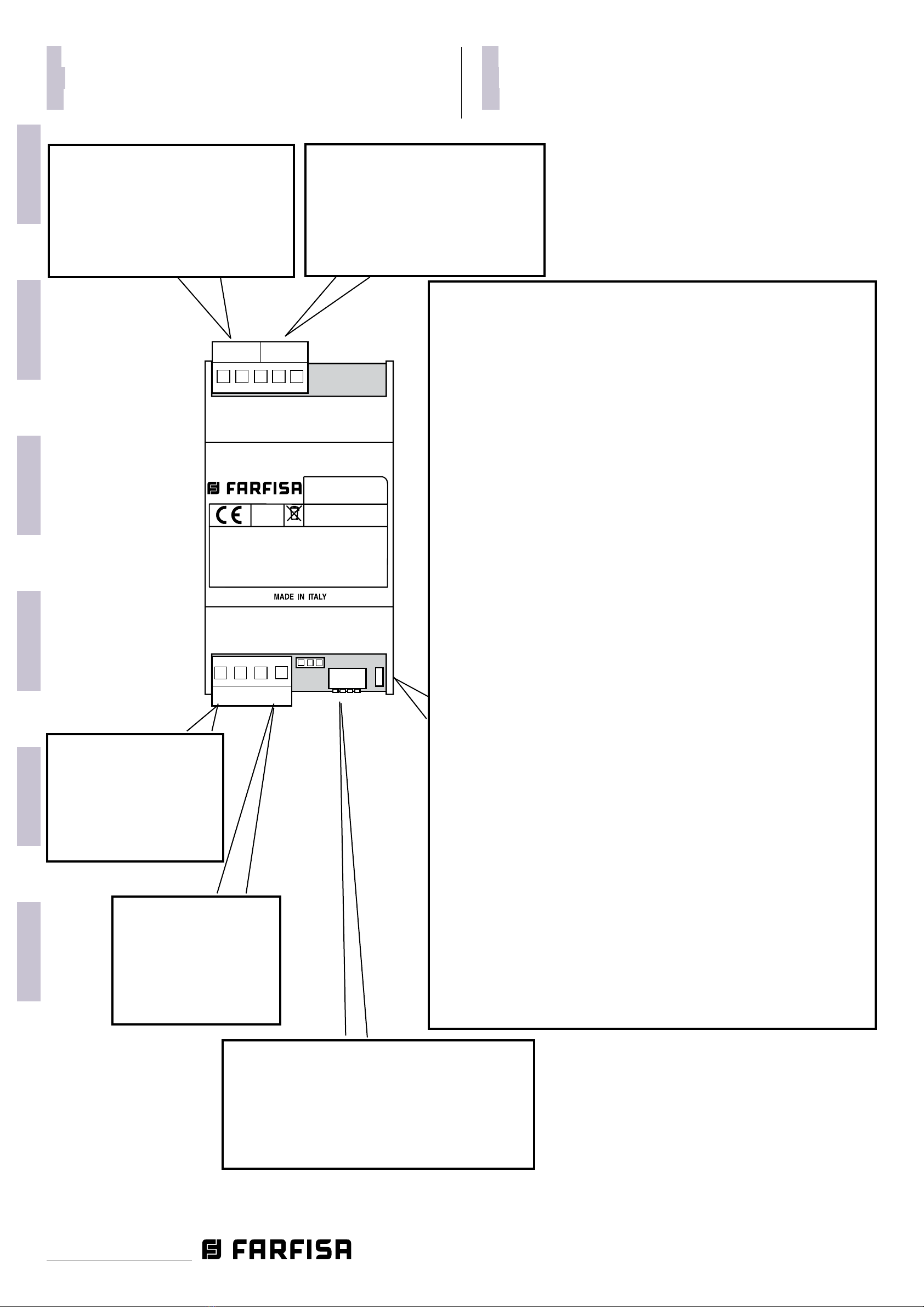
Der Videomodulator VM2521 ist an einem
DUO-Abschnitt in Stellung zu bringen und
verbindeteineoderzweiVideo-Farbkameras
(PAL-Verfahren) mit dem System (Eingänge
V1-M1 und V2-M2, wobei V das Videosignal
und M die Videomasse darstellen).
Achtung: der korrekte Systembetrieb
erfordert, dass die Videomasse bei
den zusätzlichen Videokameras vom
Erdleiter getrennt wird.
Je Eingang (V1-M1 oder V2-M2) können zwei
der den Außenstellen (231 – 253) vorbehal-
tenen Adresse gespeichert werden. Z. B. dem
Videoeingang Nr. 1 die Adresse 232 und dem
Videoeingang Nr. 2 die Adresse 233 zugewie-
sen werden. Bei einer Verbindung mit dem
Eingang 232 wird das Bild der ersten Kamera
empfangen, bei einer Verbindung mit dem
Eingang 233 das Bild der zweiten Kamera.
OhneweitereEinstellungenkannderModula-
torzusammenmitdemBetriebals"unabhän-
giges Gerät", an das er von jeder beliebigen
InnenstationüberdieEinschaltautomatik(un-
ter Verwendung der Adressen seiner beiden
Eingänge) angeschlossen werden kann, als
"von einer bereits im System vorhandenen
TürstationgesteuertesGerät".Könnenseine
Kameras während des Gesprächs alternativ
zur Kamera der Türeinheit angezeigt werden
(fürBetriebsdetailsundProgrammierungsie-
hedieBetriebsanleitungfürdieAußenstelle,
die den Modulator steuert).
Achtung: Die als Schnittstellen für den
VideomodulatorVM2521eingerichteten
AußenstellensindüberdasPrüfverfah-
ren PDX1 ausgewiesen.
Programmierung mit der DUO System
App.
Das Gerät kann vollständig über Bluetooth
programmiertwerden,indemSiedieApp"DUO
System" (verfügbar für iOS und Android) auf
Ihr Smartphone oder Tablet herunterladen.
Es ist notwendig, um:
ein Bluetooth-Programmiergerät Artikel
PGR2991BT oder XE2921 an das System
anzuschließen;
stellen Sie alle Dip-Schalter von SW1 auf
ON:
ON
1234
LED1 wird schnell blinken;
Önen Sie die App "DUO System" und gehen
Sie nach der Verbindung mit dem Blueto-
oth-Programmiergerät in den Bereich der
lokalen Programmierung und wählen Sie
VM2521;
führen Sie die Programmierung durch,
schalten Sie alle Dip-Schalter von SW1 in
die Position OFF
4
3
2
1
ON
.
Die LED1 blinkt wieder langsam.
WenneinBluetooth-Programmiergerät
nicht verwendet werden kann, gibt es
ein "Notfall"-Programmierverfahren,
das in den folgenden Abschnitten
beschrieben wird.
Manuelle Programmierung.
Im Folgenden werden die möglichen Kongu-
rationenfür dieVerwendung des Modulators
unddieentsprechendenProgrammierschritte
dargestellt:
- anschluss von nur einer Kamera an den
Modulator (Videoeingang #1);;
- anschluss von zwei Kameras an den Mod-
ulator (Videoeingang #1 und #2);
- zyklische Anzeige von zwei an den Mod-
ulator angeschlossenen Kameras (Vid-
eoeingang #1 und #2).
Programmierung für denAnschluss von
nur einer Kamera (Videoeingang #1 -
Code 01).
VerwendenSie eine beliebigeinterneStation,
die an den Videomodulator angeschlossen
werden kann, und gehen Sie wie unten bes-
chrieben vor:
speichernSieineinerTastederinternenSta-
tion die Adresse, die Sie dem Videoeingang
#1 des Modulators zuweisen möchten;
stellen Sie am Modulator den DIP-Schalter
SW1 so ein, dass der Code 01 eingestellt ist
4
3
2
1
ON
LED1 wird schnell blinken;
drücken Sie an der internen Station die
Taste, die zuvor mit der Adresse program-
miert wurde, die dem Eingang zugewiesen
werdensoll.DieLED1schaltetsichfüretwa
1 Sekunde aus und beginnt dann wieder
schnellzublinken,um anzuzeigen, dass die
Programmierung durchgeführt wurde;
alle DIP-Schalter von SW1 in die Position
OFF zurückstellen. Die LED1 blinkt wieder
langsam.
Programmierung für denAnschluss von
zwei Kameras (Videoeingang #1 - Code
01 und Videoeingang #2 - Code 06).
VerwendenSie eine beliebigeinterneStation,
die an den Videomodulator angeschlossen
werden kann, und gehen Sie wie unten bes-
chrieben vor:
speichernSieineinerTastederinternenSta-
tion die Adresse, die Sie dem Videoeingang
#1 des Modulators zuweisen möchten;
stellen Sie am Modulator den DIP-Schalter
SW1 so ein, dass der Code 01 eingestellt ist
4
3
2
1
ON
LED1 wird schnell blinken;
drücken Sie an der internen Station die
Taste, die zuvor mit der Adresse program-
miert wurde, die dem Eingang zugewiesen
werdensoll.DieLED1schaltetsichfüretwa
1 Sekunde aus und beginnt dann wieder
schnellzublinken,um anzuzeigen, dass die
Programmierung durchgeführt wurde;
alle DIP-Schalter von SW1 in die Position
OFF zurückstellen. Die LED1 blinkt wieder
langsam.
speichernSieineinerTastederinternenSta-
tion die Adresse, die Sie dem Videoeingang
#2 des Modulators zuweisen möchten;
stellen Sie am Modulator den DIP-Schalter
SW1 so ein, dass der Code 06 eingestellt is
4
3
2
1
ON
LED1 wird schnell blinken;
drücken Sie an der internen Station die
Taste, die zuvor mit der Adresse program-
miert wurde, die dem Eingang zugewiesen
werdensoll.DieLED1schaltetsichfüretwa
1 Sekunde aus und beginnt dann wieder
schnellzublinken,um anzuzeigen, dass die
Programmierung durchgeführt wurde;
alle DIP-Schalter von SW1 in die Position
OFF zurückstellen. Die LED1 blinkt wieder
langsam.
ProgrammierungfürdiezyklischeAnzei-
ge von zwei Kameras (Videoeingang #1
-Code02undVideoeingang#2-Code07).
VerwendenSie eine beliebigeinterneStation,
die an den Videomodulator angeschlossen
werden kann, und gehen Sie wie unten bes-
chrieben vor:
Speichern Sie in einer Taste der internen
StationdieAdresse,die Siefürdiezyklische
AnzeigederModulatoreingängeverwenden
möchten.
stellen Sie am Modulator den DIP-Schalter
SW1 so ein, dass der Code 02 eingestellt ist
4
3
2
1
ON
LED1 wird schnell blinken;
Drücken Sie an der internen Station die Ta-
ste,diezuvormitderAdresseprogrammiert
wurde,diederzyklischenAnzeigezugewie-
sen werden soll. Die LED1 schaltet sich für
etwa 1 Sekunde aus und beginnt dann wie-
derschnellzublinken,umanzuzeigen,dass
die Programmierung durchgeführt wurde;
alle DIP-Schalter von SW1 in die Position
OFF zurückstellen. Die LED1 blinkt wieder
langsam.
stellen Sie am Modulator den DIP-Schalter
SW1 so ein, dass der Code 07 eingestellt ist
4
3
2
1
ON
LED1 wird schnell blinken;
Drücken Sie an der internen Station die Ta-
ste,diezuvormitderAdresseprogrammiert
wurde,diederzyklischenAnzeigezugewie-
sen werden soll. Die LED1 schaltet sich für
etwa 1 Sekunde aus und beginnt dann wie-
derschnellzublinken,umanzuzeigen,dass
die Programmierung durchgeführt wurde;
alle DIP-Schalter von SW1 in die Position
OFF zurückstellen. Die LED1 blinkt wieder
langsam.
Gespeicherte Daten löschen (Code 11).
Um gespeicherte Daten zu löschen:
bringen Sie die Mikroschalter SW1 in die
Stellung, in der sie den Code 11 bilden
4
3
2
1
ON
LED1 blinkt schnell,
warten Sie etwa 4 Sekunden lang, LED1
bleibt durchgehend eingeschaltet.
BringenSiedenMikroschalter3inON-Stel-
lung
4
3
2
1
ON
.
LED1schaltetetwa2Sekundenlangabund
blinktdannwiederschnell.Allegespeicher-
ten Daten wurden gelöscht.
alle DIP-Schalter von SW1 in die Position
OFF zurückstellen. Die LED1 blinkt wieder
langsam.
Achtung: Das Verlassen des Pro-
grammiermodus erfolgt, wenn alle
DIP-Schalter von SW1 in der Position
OFF stehen:
4
3
2
1
ON

ITALIANO
ENGLISHFRANÇAISESPAÑOLPORTUGUÊSDEUTSCH
- 10 - Mi 2523/1
1234
VM2521
LI - LI:
LO-LO:
PDX1
Line input - 3.5 W
Line output
LI
LI
LO
LO
M1 V1M2 V2
4
3
2
1
ON
ON
OFF
IT Tabella 1 - Posizione dei microinterruttori di SW1 e relativa programmazione
EN Table 1 - Position of SW1’s microswitches and related programming
FR Tableau 1 - Position des micro-interrupteurs de SW1 et relative programmation
ES Tabla 1 - Posición de los microinterruptores de SW1 y relativa programación
PT Tabela 1 -Posição dos micro-interruptores de SW1 e relativa programação
DE Tabelle 1 - Position der Mikroschalter von SW1 und seine Programmierung
Posizione micro-interruttori SW1
Position of SW1’s dip switches
Position micro-interrupteurs SW1
Posición micro-interruptores SW1
Posição dos micro-interruptores SW1
DIP-Schalter-Position SW1
Programmazione
Programming
Programmation
Programación
Programação
Programmierung
Primo indirizzo ingresso video #1
First address of video input #1
Première adresse entrée vidéo #1
Primera dirección de ingreso vídeo#1
Primeiro endereço de entrada de vídeo #1
Videoeingang-Erstadresse #1
SW1
4
3
2
1
ON
4
3
2
1
ON
4
3
2
1
ON
4
3
2
1
ON
4
3
2
1
ON
4
3
2
1
ON
Secondo indirizzo ingresso video #1
Second address of video input #1
Seconde adresse entrée vidéo #1
Segunda dirección de ingreso video#1
Segundo endereço de entrada de vídeo #1
Videoeingang-Zweitadresse #1
Primo indirizzo ingresso video #2
First address of video input #2
Première adresse entrée vidéo #2
Primera dirección de ingreso vídeo#2
Primeiro endereço de entrada de vídeo #2
Videoeingang-Erstadresse #2
Secondo indirizzo ingresso video #2
Second address of video input #2
Seconde adresse entrée vidéo #2
Segunda dirección de ingreso video#2
Segundo endereço de entrada de vídeo #2
Videoeingang-Zweitadresse #2
Cancellazione dati in memoria
Erasing memory data
Élimination des données en mémoire
Supresión de datos en la memoria
Apagar dados na memória
Gespeicherte Daten löschen
Programmazione via Bluetooth
Programming via Bluetooth
Programmation via Bluetooth
Programación por Bluetooth
Programação via Bluetooth
Programmierung über Bluetooth

ITALIANO
ENGLISHFRANÇAISESPAÑOLPORTUGUÊS
DEUTSCH
- 11 -
Mi 2523/1
IT Esempio di programmazione
Ingresso video #1 = 232, 240.
Ingresso video #2 = 233, 240.
ON
1234
SW1
ON
1234
SW1
ENTRATA IN PROGRAMMAZIONE
ENTERING THE PROGRAMMING MODE
ENTRER EN MODE DE PROGRAMMATION
ACCESO ALLA PROGRAMACI N
Ó
ENTRADA EM PROGRAMA O
ÇÃ
APUFRUFEN DES IERMODUSROGRAMM
USCITA DALLA PROGRAMMAZIONE
EXIT THE PROGRAMMING MODE
QUITTER LA PROGRAMMATION
SALIDA DE LA PROGRAMACI NÓ
SADADA PROGRAMA OÍÇÃ
VPERLASSEN DES ROGRAMMIERMODUS
#2 (233)
ON
ON
1
1
2
2
3
3
4
4
SW1
SW1
#1 (240)
#2 (240)
#1 (232)
233
ON
1234
SW1
+Astro
Exhito
Sette
Zhero
+
+
+
232
Astro
Exhito
Sette
Zhero
Astro
Exhito
Sette
Zhero
240
240
Astro
Exhito
Sette
Zhero
ES Ejemplo de programación
Entrada de video #1 = 232, 240.
Entrada de video #2 = 233, 240.
PT Exemplo de programação
Entrada de video #1 = 232, 240.
Entrada de video #2 = 233, 240.
DE
Beispiel für Programmierung
Videoeingang #1 = 232, 240.
Videoeingang #2 = 233, 240.
EN Example of programming
Video input #1 = 232, 240.
Video input #2 = 233, 240.
FR Exemple de programmation
Entrée vidéo #1 = 232, 240.
Entrée vidéo #2 = 233, 240.

ITALIANO
ENGLISHFRANÇAISESPAÑOLPORTUGUÊSDEUTSCH
- 12 - Mi 2523/1
ACI srl Farsa Intercoms
Via E. Vanoni, 3 • 60027 Osimo (AN) • Italy
Tel: +39 071 7202038 (r.a.) • Fax: +39 071 7202037
e-mail: info@farsa.com • www.farsa.com
Directive 2012/19/EU (WEEE-RAEE)
Smaltire il dispositivo secondo quanto prescritto dalle norme per la tutela dell'ambiente.
Dispose of the device in accordance with environmental regulations.
Écouler le dispositif selon tout ce qu'a été prescrit par les règles pour la tutelle du milieu.
Eliminar el aparato según cuánto prescrito por las normas por la tutela del entorno.
Disponha do dispositivo conforme regulamentos ambientais.
Werden Sie das Gerät in Übereinstimmung mit Umweltregulierungen los.
La ACI Srl Farsa Intercoms si riserva il diritto di modicare in qualsiasi momento i prodotti qui illustrati.
ACI Srl Farsa Intercoms reserves the right to modify the products illustrated at any time.
La ACI Srl Farsa Intercoms se réserve le droit de modier à tous moments les produits illustrés.
Mi2523/1
Cod. M527055210
ACI Srl Farsa intercoms se reserva el derecho de modicar en cualquier momento los productos ilustrados aquí.
E’ reservada a ACI Srl Farsa intercoms o direito de modicar a qualquer momento os produtos aqui ilustrados.
Änderungen vorbehalten.
Table of contents
Popular Modulator manuals by other brands

Scientific Atlanta
Scientific Atlanta Continuum DVP eXtra Dense QAM Array 24 Configuration guide

Radio Shack
Radio Shack Video RF Modulator owner's manual

Ekselans
Ekselans MD HD L 4K user manual

TANDBERG
TANDBERG SM6630 user guide

Erica Synths
Erica Synths DIY MODULATOR Guide to assembly

Jensen
Jensen KVFM1 How to install and operate