6
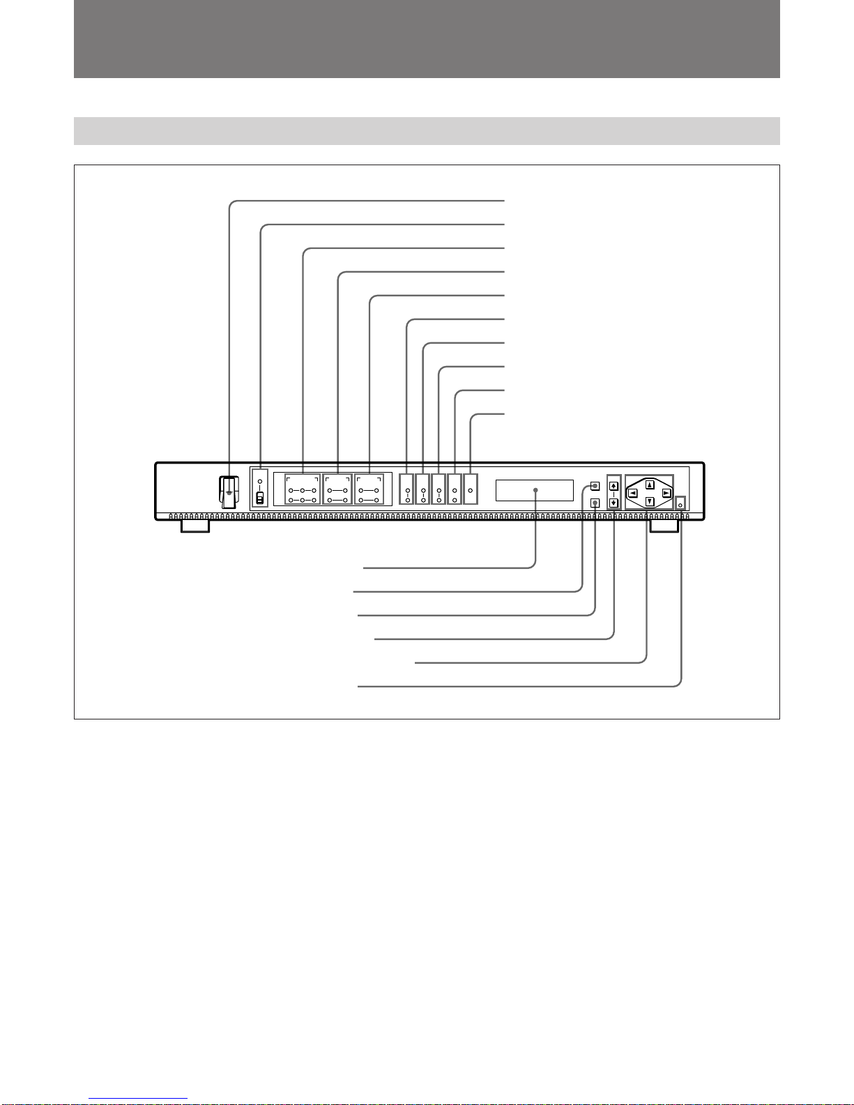
Locations and Functions of Parts and Controls
4SOURCE SEL (source selection) indicators
OUT1 indicators
SOURCE1: Lights up when input signals from the
optional board in the IN1section of the DSM-T1
are output from the optional board in the OUT1
section of the unit.
SOURCE2: Lights up when input signals from the
optional board in the IN2section of the DSM-T1
are output from the optional board in the OUT1
section of the unit.
To select the input signal source from the optional
board in the OUT1section, select “01: OUT1 SRC
SEL” in the menu.
For more information, see “Menu Setup” (page 10).
OUT2 indicators
SOURCE1: Lights up when input signals from the
optional board in the IN1section of the DSM-T1
are output from the optional board in the OUT2
section of the unit.
SOURCE2: Lights up when input signals from the
optional board in the IN2section of the DSM-T1
are output from the optional board in the OUT2
section of the unit.
To select the input signal source from the optional
board in the OUT2section, select “02: OUT2 SRC
SEL” in the menu.
For more information, see “Menu Setup” (page 10).
5ANALOG AUDIO indicators
OUT1 indicators
CH 1/2 or CH 3/4 (or both) indicator(s) lights up when
the BKSM-R103 Analog Output Board is installed in
the OUT1section of the unit, and when audio signals
are output from the BKSM-R103.
To select the input signal source from the optional
board in the OUT1section, select “41: OUT1
AUDIO CH” in the menu.
OUT2 indicators
CH 1/2 or CH 3/4 (or both) indicator(s) lights up when
the BKSM-R103 Analog Output Board is installed in
the OUT2section of the unit, and when audio signals
are output from the BKSM-R103.
To select the input signal source from the optional
board in the OUT2section, select “51: OUT2
AUDIO CH” in the menu.
6VIDEO STD (video standard) indicators
525: Lights up when the unit is set up in the 525
standard.
625: Lights up when the unit is set up in the 625
standard.
To select the broadcasting standard, select “03:
VIDEO STD” in the menu.
For more information, see “Menu Setup” (page 10).
7FREQ BW (frequency bandwidth) indicators
36M: Lights up when the frequency bandwidth is
36 MHz.
18M: Lights up when the frequency bandwidth is
18 MHz.
To select the frequency bandwidth, select “11: FREQ
BW” in the menu.
For more information, see “Menu Setup” (page 10).
8FEC RATE (Forward Error Correction rate)
indicators
7/8: Lights up when the FEC rate is 7/8.
3/4: Lights up when the FEC rate is 3/4.
To select the FEC rate, select “12: FEC RATE” in the
menu.
For more information, see “Menu Setup” (page 10).
9RF CONDITION indicators
Indicate the siginal receiving conditions.
Green: Indicates that the siginal receiving conditions
are good.
Yellow: Indicates that picture or sound noise may
appear.
If the condictions are even worse, a warning message
appears in the display window.
For more information about warning messages, see
“Operation Warnings” (page 15).
!º ALARM indicator
When a fault is detected while the unit is in operation,
the ALARM indicator lights up. In this case, a
warning message (0X WARNING) appears in the
display window. The ALARM indicator turns off
when the operation returns to normal.
For more information about warning messages, see
“Operation Warnings” (page 15).