Thor Broadcast H-XX-SDI-QAM-IPLL User manual

Thor Fiber Tel: (800) 521-84 Email: sales@thorfiber.com https://thorbroadcast.com/ http://www.thormodulators.com/
User Manua
l
1-4 HDMI & SDI
Encoder Modulator
H-XX-SDI-QAM-IPLL
H-XX-HDMI-QAM-IPLL
Revision 06212017

HDMI/SDI-QAM-IPLL
Thor Fiber Tel: (800) 521-84 Email: sales@thorfiber.com https://thorbroadcast.com/ http://www.thormodulators.com/
A Note from Thor Broadcast about this Manual
Intended Audience
This user manual has been written to help people who have to use, integrate and to install the product.
Some chapters require some prerequisite knowledge in electronics and especially in broadcast
technologies and standards.
Disclaimer
No part of this document may be reproduced in any form without the written permission of Thor
Broadcast.
The contents of this document are subject to revision without notice due to continued progress in
methodology, design and manufacturing. Thor shall have no liability for any error or damage of any
kind resulting from the use of this document.
Copy Warning
This document includes some confidential information. Its usage is limited to the owners of the
product that it is relevant to. It cannot be copied, modified, or translated in another language
without prior written authorization from Thor Broadcast.

HDMI/SDI-QAM-IPLL
Thor Fiber Tel: (800) 521-84 Email: sales@thorfiber.com https://thorbroadcast.com/ http://www.thormodulators.com/
Table of Contents
CHAPTER 1 - INTRODUCTION......................................................................................................................... 4
1.1 PRODUCT OVERVIEW ..................................................................................................................................... 4
1.2 KEY FEATURES ................................................................................................................................................... 4
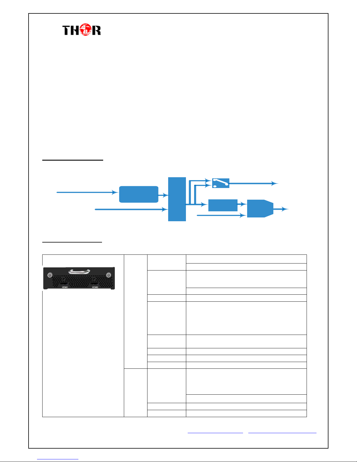
1.3 PRINCIPLE CHART.......................................................................................................................................... 5
1.4 SPECIFICATIONS................................................................................................................................................. 5
CHAPTER 2 - INSTALLATION GUIDE ................................................................................................................ 8
2.1 GENERAL PRECAUTIONS................................................................................................................................. 8
2.2 POWER PRECAUTIONS..................................................................................................................................... 8
2.3 DEVICE’S INSTALLATION FLOW CHART ILLUSTRATE AS FOLLOWING:................................................................ 8
2.4 ENVIRONMENT REQUIREMENT........................................................................................................................ 9
2.5 GROUNDING REQUIREMENT......................................................................................................................... 10
CHAPTER 3 - OPERATION ............................................................................................................................. 11
3.1.1LCD MENU STRUCTURE ............................................................................................................................ 11
3.1.2 INITIAL STATUS.......................................................................................................................................... 13
3.2GENERAL SETTING FOR MAIN MENU.............................................................................................................. 13
CHAPTER 4 - WEB NMS OPERATION ............................................................................................................ 20
4.1 LOGIN.......................................................................................................................................................... 20
4.2 OPERATION.................................................................................................................................................. 21
ENCODER MODULATOR QUICK SETUP WITH GUI & VCT .............................................................................. 32
INTRO –GUI &VCT.......................................................................................................................................... 33
......................................................................................................................................................................... 36
VIRTUAL CHANNELS........................................................................................................................................... 37
ENCODER MODULATOR IPTV SETUP ............................................................................................................ 43
INTRO................................................................................................................................................................ 44
CHAPTER 5 - TROUBLESHOOTING ................................................................................................................ 49
CHAPTER 6 -PACKING LIST ........................................................................................................................... 50
CHAPTER 7 - APPLICATION........................................................................................................................... 51
7.1 APPLICATION EXAMPLE................................................................................................................................ 51
APPENDIX ................................................................................................................................................ 53

HDMI/SDI-QAM-IPLL
Thor Fiber Tel: (800) 521-84 Email: sales@thorfiber.com https://thorbroadcast.com/ http://www.thormodulators.com/
Chapter 1 - Introduction
1.1 Product Overview
The Thor Broadcast HDMI and SDI encoder modulators are an all-in-one device that
integrates encoding (MPEG-2, MPEG-4/AVC H.264), modulation, and converts
HDMI/SDI (model dependent) to a digital RF output signal and IPTV stream
simultaneously.
To meet various requirements, these Thor Broadcast Pro-DVB headend units are also
equipped with 1 ASI input, and outputs with 2 ASI ports and 1 IP port.
The signal source could vary from satellite receivers, closed-circuit television cameras,
Blu-ray players, and antenna (off air). Its output signals are to be received by TVs, STB,
etc. with the correlated standard the unit is set to encode with QAM (ATSC, DVB-T,
DVB-C).
The ever popular low latency modulators are widely used everywhere such as the mall,
market hall, theatre, hotels, restaurants, stadiums, race tracks, amphitheaters and etc. for
advertising, monitoring, training and educating in company, schools, campuses, and
healthcare. Recently these units have been deployed in countless professional and
collegiate stadiums, universities, house of worship, Nascar and other various raceways for
their power and ease of use.
1.2 Key features
HDMI/SDI… (1-4)inputs,1*ASI in for re-mux; 1*RF in for RF mux
MPEG2 HD/SD & MPEG4AVC H.264 HD/SD video encoding
1/ 2* channels in
MPEG4-AAC; MPEG2-AAC; MPEG1 Layer Ⅱand Dolby DigitalAC3 2.0( Optional)
audio encoding
Dolby Digital AC3 pass through
Huge video buffer (for SDI interface), free to switch video sources
Dialog Normalization(Optional)
CC (closed caption ) for SDI
Support low delay encoding mode

HDMI/SDI-QAM-IPLL
Thor Fiber Tel: (800) 521-84 Email: sales@thorfiber.com https://thorbroadcast.com/ http://www.thormodulators.com/
VBR/CBR rate control mode
PSI/SI editing
PCR adjusting
PID re-mapping and pass through
DVB-C RF out and ASI out; IP out
LCN (Logical Channel Number) support
Modular design 1RU
LCD display, Remote control and firmware
Web-based NMS management; Updates via web
Lowest cost per channel
1.3 Principle Chart
MUX
Modulating
ASI In
ASI&IP Output
MPEG-2 HD/SD
MPEG-4 HD/SD
Encoding
HDMI/SDI
Source
RF In
Built-in
Combiner RF
1.4 Specifications
HDMI Encoding Input
Video
Input
Option 1: HDMI*1
Option 2: HDMI*2
Encoding
MPEG2; MPEG4 AVC/H.264 (for option 1:
HDMI*1)
MPEG4 AVC/H.264 (for option 2:HDMI*2)
Bitrate
1-19.5Mbps
Resolution
1920*1080_60P, 1920*1080_50P,
(-for MPEG4 AVC/H.264 only)
1920*1080_60i, 1920*1080_50i,
1280*720_60p, 1280*720_50P
720*480_60i, 720*576_50i
Low Delay
Normal, Mode 1, Mode 2
(for option 1: HDMI*1)
Rate Control
VBR/CBR
Chroma
4:2:0
Aspect Ratio
16:9,4:3
Audio
Encoding
MPEG1 Layer II; LC-AAC; HE-AAC and Dolby
Digital AC3 2.0 (Optional) (for option 1:
HDMI*1)
MPEG1 Layer II(for option 2: HDMI*2)
Sample rate
48KHz
Bitrate
64/96/128/ 192/256/320kbps

HDMI/SDI-QAM-IPLL
Thor Fiber Tel: (800) 521-84 Email: sales@thorfiber.com https://thorbroadcast.com/ http://www.thormodulators.com/
SDI Encoding Input
Input
Option 1:SDI*1
Option 2:SDI*2
Encoding
MPEG2; MPEG4 AVC/H.264
Bitrate
1-19.5Mbps
Resolution
1920*1080_60P, 1920*1080_50P,
(-for MPEG4 AVC/H.264 only)
1920*1080_60i, 1920*1080_50i,
1280*720_60p, 1280*720_50P
720*480_60i, 720*576_50i
Low Delay
Normal, Mode 1, Mode 2
Rate Control
VBR/CBR
Chroma
4:2:0
Aspect Ratio
16:9,4:3
Audio
Encoding
MPEG1 Layer II ,MPEG2-AAC, MPEG4-AAC
and Dolby Digital AC3 2.0( Optional)
Sample rate
48KHz
Bitrate
64/96/128/ 192/256/320kbps
Modulator Section
DVB-C
Standard
J.83A (DVB-C), J.83B, J.83C
MER
≥43dB
RF frequency
30~960MHz, 1KHz step
RF output level
-30~ -10dbm (77~97 dbµV), 0.1db
step
Symbol rate
5.000~9.000Msps adjustable
RF Out
1*DVB-C;
4*DVB-C carriers combined output
J.83A
J.83B
J.83C
Constellation
16/32/64/1
28/256QAM
64/ 256
QAM
64/
256
QAM
Bandwidth
8M
6M
6M
General
System
Local interface
LCD + control buttons
Remote management
Web NMS
Stream Out
2 ASI out (BNC type);
IP (MPTS/SPTS) out (RJ45, 100M)
NMS interface
RJ45, 100M
Language
English
Physical
Specifica
tion
Power supply
AC 100V~240V
Dimensions
482*300*44mm (19” rack)
267*250*44mm (portable)
Weight
4.5 kg (19” rack)
2.5 kg (portable)
Operation
temperature
0~45℃

HDMI/SDI-QAM-IPLL
Thor Fiber Tel: (800) 521-84 Email: sales@thorfiber.com https://thorbroadcast.com/ http://www.thormodulators.com/
1.5Appearance and Description
Front Panel Illustration
1 2 3 4 5 6 7 8 9
①LCD Screen
②NMS Port
③Data Port
④Power and Alarm Indicators
⑤TS Lock Indicators
⑥Directional: Up, Down, Left, and Right Buttons
⑦Enter Button: to confirm
⑧Menu Button : to go back one step
⑨Lock Button: press to lock set
Rear Panel Illustration
1 2 3 45 7
8 9
①HDMI or HD-SDI input port
②RF In Port
③RF Out Port
④ASI Input Port
⑤ASI Output port 1&2
⑥Power Switch
⑦Power supply socket
⑧RF out port
⑨Grounding

HDMI/SDI-QAM-IPLL
Thor Fiber Tel: (800) 521-84 Email: sales@thorfiber.com https://thorbroadcast.com/ http://www.thormodulators.com/
Chapter 2 - Installation Guide
Please read the entire section in full before installing or operating your new Thor Broadcast
encoder to eliminate any chance of creating a faulty environment or recklessly damaging the
unit.
2.1 General Precautions
Must be operated and maintained in an area free of dust and debris.
The cover should be securely fastened, do not open the cover of the chassis when the power is on.
This will also void Thor’s manufacturer’s warranty.
After installation, securely stow away all loose cables, external antenna, and others.
2.2 Power precautions
Be careful when connecting a power source to the device.
Do not operate in wet or damp areas. Make sure the extension cable is in good condition
Make sure the power switch is off before you start to install the device
2.3 Device’s Installation Flow Chart Illustrate as following:
Connecting
Grouding
Wire and
Power
Cord
Acquisition
Check Installing
Device Setting
Parameter Running
Device
Connecting
Signal
cable

HDMI/SDI-QAM-IPLL
Thor Fiber Tel: (800) 521-84 Email: sales@thorfiber.com https://thorbroadcast.com/ http://www.thormodulators.com/
2.4 Environment Requirement
Item
Requirement
Rack Space
When installing unit on rack, the distance between 2 rows of
machine frames should be 1.2~1.5m and the distance against
wall should be no less than 0.8m.
Rack Room
Electric Isolation, Dust Free, HVAC
anti-static material:1X10⁷~1X10¹⁰, Grounding current
limiting resistance: 1M(Floor bearing should be greater than
450Kg/㎡)
Environment
Temperature
5~40℃(sustainable ),0~45℃(short time),
installing air-conditioning is recommended
Relative Humidity
20%~80% sustainable 10%~90% short time
Pressure
86~105KPa
Door & Window
Installing rubber strip for sealing door-gaps and dual level
glasses for window
Fire Protection
Fire alarm system and extinguisher
Power
Device power, HVAC and lighting should be independent to
each other. Device power requires AC 110V±10%, 50/60Hz or
AC 220V±10%, 50/60Hz. Please carefully check before
running.

HDMI/SDI-QAM-IPLL
Thor Fiber Tel: (800) 521-84 Email: sales@thorfiber.com https://thorbroadcast.com/ http://www.thormodulators.com/
2.5 Grounding Requirement
It is important to keep this device grounded to ensure all of the modules function correctly.
Correctly grounding the device will also help prevent any electrical interference, lightening.
Etc. Also it helps reject minor interference that may disrupt the devices ability to function
smoothly. General rule of them, make sure the device is grounded when installing anywhere.
Always use copper wire. When applied correctly the ground must be wrapped well to
ensure maximum conduction so it can reduce any high frequencies. The copper ground wire
should also be as short and thick as possible
Installer must make sure that the two ends of the ground are well conducted and have
appropriate anti-rust properties.
It is prohibited to use any other device as part of the grounding electric circuit.
The area of the conduction between the ground wire and device’s frame should be no less
than 25 ㎡.

HDMI/SDI-QAM-IPLL
Thor Fiber Tel: (800) 521-84 Email: sales@thorfiber.com https://thorbroadcast.com/ http://www.thormodulators.com/
Chapter 3 - Operation
Keyboard Function Description:
MENU: Cancel current entered value, resume previous setting; Return to previous menu.
ENTER: Activate the parameters which need modifications, or confirm the change after modification.
LEFT/RIGHT: Choose and set the parameters.
UP/DOWN: Modify activated parameter or paging up/down when parameter is inactivated.
LOCK: Lock the screen/cancel the lock state. After pressing the lock key, the LCD will display the
current configuring state.
3.1.1LCD Menu Structure
2 Input Sets
2.1 Input 1
2.2 Input 2
2.3 Input 3 2.3.1 Parse Program
Switch On
Initializing
1 Status
Video
Audio
2.3.2 Mux Program
Same content as “Input 1”
Audio Bitrate
1.1 Uptime

HDMI/SDI-QAM-IPLL
Thor Fiber Tel: (800) 521-84 Email: sales@thorfiber.com https://thorbroadcast.com/ http://www.thormodulators.com/
4 TS config
4.1 Output A
4.2 Output B
4.3 Output C
4.4 Output D
4.5 Output E
5 Network 5.1.1 NMS IP
5.1.2 Subnet Mssk
5.1.4 MAC Address
5.1.6 Reset Password
5.1.3 Gateway
5.1.5 Web NMS Port
3 Modulator
4.1 Output A
4.2 Output B
4.3 Output C
4.4 Output D
6 System
6.1 Save Config
6.2 Load Saved CFG
6.4 LCD time-out
6.5 Version
6.3 Factory reset
4.1 RF on
4.2 Standard
4.3 Constellation
4.4 Symbol Rate
4.5 RF frequency
4.6 RF level
4.7 ASI output
Same content as “Output A”
TSID
ONID
ASI Output
5.1 Parse Program
5.2 Mux Program
Same content as “Output A”

HDMI/SDI-QAM-IPLL
Thor Fiber Tel: (800) 521-84 Email: sales@thorfiber.com https://thorbroadcast.com/ http://www.thormodulators.com/
3.1.2 Initial Status
After powering on the device,it will take a few seconds to initialize the system
DVB-C: indicates the modulation standard of this device.
A/B/C/D: indicates the 4 carrier outputs
XXX.XX MHz: Indicates the current output frequency (Range: 30~999MHz) of the 4 carriers
output.
X.XX Mbps: Indicates the encoding bitrate of each encoding output respectively.
3.2General setting for Main Menu
By pressing the “Lock”key on the front panel, enter the main menu. The LCD will display the
following pages:
Press UP/DOWN buttons to specify menu items, and then press ENTER to enter the submenus as
below:
1) Status
Press Enter to enter “Status”and it displays the working time duration of the device
2) Input Sets
Under this submenu, the LCD will show “2.1 Input 1”, “2.2 Input 2”and “2.3 Input 3”.
Start up…
Start OK…
DVB-C A XXX.00MHz
P1 X.XXMbps P2 X.XXMbps
1 Status
2 Input Sets
1 Status
2 Modulator
3 Modulator
4 TS Config
5 Network
6 System
1.1 Uptime
Uptime
2 Days-10:30:20
2 Days-10:30:20
2.1 Input 1
2.2 Input 2
2.3 Input 3

HDMI/SDI-QAM-IPLL
Thor Fiber Tel: (800) 521-84 Email: sales@thorfiber.com https://thorbroadcast.com/ http://www.thormodulators.com/
Under submenus 2.1 and 2.2, set the audio, video and program information for each
encoding input.
Enter Video Input to set the video corresponding parameters.
Note: Supports CC for SDI encoding only
Under submenu 2.2, set the audio corresponding parameters.
Audio format
Under the “Audio”submenu, select the audio format for this encoding input source, these
Thor Broadcast encoders support MPEG-1 Layer II, MPEG-2 AAC, MPEG-4 AAC and AC3.
Dialog Normal
Set the dialog level of this device
Video
Video format
MPEG-2 H.264
Video Bit rate
12.000Mbps
Low delay
Normal Model1 Model2 Manual
CC Switch
EIA608 EIA708 Line21 CC OFF
Resolution
1920×1080 50i
Video in Status
Locked
B frame
2
P frame
4
DTS delay
200
Audio
Audio format
MPEG-1 Layer II
Dialog Normal
-31dB

HDMI/SDI-QAM-IPLL
Thor Fiber Tel: (800) 521-84 Email: sales@thorfiber.com https://thorbroadcast.com/ http://www.thormodulators.com/
Under Audio Bit Rate can be selected by pressing “enter”key. (Bit rate range:
64/96/128/192/256/320 Kbps):
Users enter 2.3 to check the programs information and set the programs parameters.
Submenu 2.3 represents the ASI input. You can parse and select program(s) to mux out.
“Parse Program” is for checking the quantity of input programs from the corresponding
Tuner input.
“Mux Program” is for selecting programs from the ASI IN to multiplex with the output via
corresponding carrier output or ASI output (A, B, C, D, E optional). Move the triangle mark to
specify the program and press RIGHT/LEFT keys to shift the mark between “√” and “X”. (“√”: to
output the corresponding program; “X”: not to output the corresponding program)
Output A mux
Output B mux
Parse Program
Get 3 programs
Parse Program
Mux Program
Audio Bitrate
64Kbps
Program Info
Service provider
TV provider
SUB-Channel Number
1
PMT PID
0×100
PCR PID
0×103
Program Name
TV-101
Program Output
Program out enable A
Video PID
0×101
Audio PID
0×102

HDMI/SDI-QAM-IPLL
Thor Fiber Tel: (800) 521-84 Email: sales@thorfiber.com https://thorbroadcast.com/ http://www.thormodulators.com/
3) Modulator Setting
When entering the “Modulator” submenu, configure the modulating parameters for the 4 carrier output
separately:
The Thor Encoder Modulators (DVB-C Modulating) have 4 carrier outputs, “3.1”-“3.4”represent the
“Carrier A”, “Carrier B”, “Carrier C”, and “Carrier D”respectively. Enter “3.1”/“3.2”/“3.4”/“3.4”to
set the corresponding modulating parameters. Submenus (taking “3.1”as an example) are as below:
RF On
This interface decides whether to enable the RF (carrier A) output or not.
OFF: to disable programs to output through carrier A.
ON: to enable programs to output through carrier A.
Standard
There are three possible options provided for selecting your RF modulation Standard: J.83A(DVB-C),
J.83B, J.83C when the display shows them, just swipe LEFT and RIGHT key to choose.
Constellation
Three different constellations: J.83A (DVB-C), J.83B, J.83C will show on the LCD window when
3.1 Output A
3.2 Output B
3.3 Output C
3.4 Output D
3.1 Output A
3.1.1RF On
3.1.2 Standard
3.1.5 RF Frequency
3.1.6 RF Level
3.1.3 Constellation
3.1.4 Symbol Rate
3.1.7 ASI output
RF On
Off On

HDMI/SDI-QAM-IPLL
Thor Fiber Tel: (800) 521-84 Email: sales@thorfiber.com https://thorbroadcast.com/ http://www.thormodulators.com/
Constellation been entered.
J.83A (DVB-C) contains 16QAM, 32QAM, 64QAM, 128QAM, and 256QAM;
J.83B contains 64QAM, 256QAM; THIS I NORTH AMERICA STANDARD
J.83C contains 64QAM, 256QAM.
16QAM: Quadrature Amplitude Modulation is 16
32 QAM: Quadrature Amplitude Modulation is 32
64QAM: Quadrature Amplitude Modulation is 64
128QAM: Quadrature Amplitude Modulation is 128
256QAM: Quadrature Amplitude Modulation is 256
When the display shows, swipe LEFT and RIGHT key to choose and press “ENTER” for confirm.
Symbol Rate
The symbol rate range for both J.83A(DVB-C) & J.83C is 5Msps to 9Msps and J.83B is fixed and
cannot be changed.
RF Frequency
The RF output frequency range is from 30 to 999MHz with 1K stepping. After entering the RF
frequency setting submenu, press LEFT, RIGHT, UP, and DOWN buttons to adjust the frequency and
confirm by press ENTER button.
RF level
The RF attenuation range is from -30~-10dbm (81~97dbµV) with 0.1db step. After entering this
setting submenu, shift UP/DOWN/LEFT/RIGHT key to set the output level and press ENTER to
confirm.
RF Frequency
750.000 MHz
RF Level
-10.0 dbm

HDMI/SDI-QAM-IPLL
Thor Fiber Tel: (800) 521-84 Email: sales@thorfiber.com https://thorbroadcast.com/ http://www.thormodulators.com/
ASI Output:
These Thor modulator’s (DVB-C Modulating) have a quad-carrier output A, B, C, D and 1 ASI
output E.
Output A: the ASI output programs are same as carrier output A.
Output B: the ASI output programs are same as carrier output B.
Output C: the ASI output programs are same as carrier output C.
Output D: the ASI output programs are same as carrier output D.
Output E: the ASI output programs are set separately.
4) TS Configuration
Enter each menu to configure the TS ID and Original Network ID for the 4 carriers and ASI output.
5) Network
Network contains “5.1 NMS”and“5.2 IP Stream”.
“5.1 NMS”is for setting the network parameters for the connection between the device and PC.
ASI Output
Output A
4.1 Output A
4.2 Output B
4.3 Output C
4.4 Output D
5.1.5 Web NMS Port
5.1.6 Reset Password
5.1.3 Gateway
5.1.4 MAC Address
5.1.1 NMS IP
5.1.2 Subnet Mask
5.1 NMS
5.2 IP Stream
4.5 Output E

HDMI/SDI-QAM-IPLL
Thor Fiber Tel: (800) 521-84 Email: sales@thorfiber.com https://thorbroadcast.com/ http://www.thormodulators.com/
“IP Stream”is for configuring the 4 SPTS output respectively.
6) System
It contains 5 submenus where you can save/load configurations.
5.2.1 IP out 1
5.2.2 IP out 2
5.2.3IP out 3
5.2.4IP out 4
Data Enable
Null PKT Filter
Output IP
Output Port
Service IP
Subnet Mask
Gateway
Protocol
6.1 Save Config
6.2 Load Saved CFG
6.3Factory Reset
6.4LCD time-out
6.5 Version
NMS IP
192.168.000.136
Subnet mask
255.255.255.000
Gateway
192.168.000.001
MAC address
201110140940
Reset password?
Yes NO
Web Manage Port
00080

HDMI/SDI-QAM-IPLL
Thor Fiber Tel: (800) 521-84 Email: sales@thorfiber.com https://thorbroadcast.com/ http://www.thormodulators.com/
Chapter 4 - WEB NMS Operation
For setting configurations you can use the front panel; also you are able to control and set the
configurations on any computer by connecting the device to the web NMS Port. You should ensure that
the computer’s IP address is different from the THOR 4-ADHD’s IP address; otherwise, it would cause
IP conflict.
4.1 Login
The default IP of this device is 192.168.0.136. We can modify the IP through the front panel.
Connect the pc and the device with net cable, and use ping command to confirm they are on the same
network segment.
E.G. the PC IP address is 192.168.99.252, we then change the device IPto 192.168.99.xxx (xxx can be
0 to 255 except 252 to avoid IP conflict).
Use any web browser to connect the device with the PC by inputting the Encoder & Modulator’s IP
address in the browser’s address bar and press Enter.
It will display the Login interface as Figure-1. Input the Username and Password (Both the default
Username and Password are “admin”.) and then click “LOGIN” to start the device setting
This manual suits for next models
1
Table of contents
Other Thor Broadcast Modulator manuals

Thor Broadcast
Thor Broadcast H-HDMI-RF-PETIT User manual

Thor Broadcast
Thor Broadcast H-HDMI-RF-PETIT User manual

Thor Broadcast
Thor Broadcast H-PCKT-MOD User manual

Thor Broadcast
Thor Broadcast H-HDMI-CC-RF User manual

Thor Broadcast
Thor Broadcast H-IPRF-16QAM User manual

Thor Broadcast
Thor Broadcast H-HDMI-RF-Petit-IR User manual

Thor Broadcast
Thor Broadcast H-16RCA-RF-MOD User manual

Thor Broadcast
Thor Broadcast H-THUNDER-8 User manual

Thor Broadcast
Thor Broadcast H-IP-32RF User manual

Thor Broadcast
Thor Broadcast H-PCKT-MOD User manual