Farmi Forest Corporation JL 601 Guide

OPERATING, MAINTENANCE AND
SPARE PARTS MANUAL
JL 601
B // En // 141001 MRu
www.normet.fi 03121060
Normet Corporation
Ahmolantie 6
FIN ---74510 PELTOSALMI
FINLAND
Tel. + 358 (0) 17 83 241
Fa
x
. + 358
(
0
)
17 823 606
1Page
From machine 03121000
SKIDDING WINCH
JL 601
IT IS VERY IMPORTANT TO READ THIS INSTRUCTION MANUAL
THOROUGHLY BEFORE USING THE MACHINE
www.normet.fi

OPERATING, MAINTENANCE AND
SPARE PARTS MANUAL
JL 601
B // En // 141001 MRu
www.normet.fi 03121060
Normet Corporation
Ahmolantie 6
FIN ---74510 PELTOSALMI
FINLAND
Tel. + 358 (0) 17 83 241
Fa
x
. + 358
(
0
)
17 823 606
2Page
WARNING SYMBOLS IN THE MANUAL
An immediate danger which may cause
serious injuries or even death.
DANGER!
Risk of injuries.
WARNING!
A general risk or danger, which may cause
material damage due to false operation.
Note!
Reminds the operator to check, service, or
repair parts of the machine etc.
NOTE!
INTRODUCTION
This manual describes the JL601 skidding winch and includes
information and maintenance instructions for a safe and efficient
machine operation.
Please, read the operation and service manual carefully even if you are
an experienced winch user. The manuals include information
required for an efficient and safe operation of the machine. Regular
maintenance guarantes economical and correct machine
operation.
The skidding winch is delivered test---run and test loaded..
All operators are obliged to carefully familiarize
and obey all safety precautions and instructions.
Note!
CUSTOMER FEEDBACK
You can send your opinions and improvement proposals via mail, fax
or via internet (eMail). We will award the best improvement proposals.

OPERATION, MAINTENANCE AND
SPARE PARTS MANUAL
JL 601
B // En // 141001 MRu
www.normet.fi
Normet Corporation
Ahmolantie 6
FIN ---74510 PELTOSALMI
FINLAND
Tel. + 358 (0) 17 83 241
Fa
x
. + 358
(
0
)
17 823 606
3Page
Normet Corporation
Ahmolantie 6, FIN--74510 PELTOSALMI, Finland
Informs that the machine, launched on to the market,
Farmi winch
(make)
JL 601
(type)
(serial number)
conforms to Machine Directives 98/37/EC, 89/366/EC to the amendments related to it as
well as to the national statutes which bring them into force.
The following unified standards have been applied to the design of the machine:
EN292--2, EN 294
The following national standards and specifications have been applied to the design of the
machine:
prEN 1553
Peltosalmi, Finland 19.02.1995
(place) (date)
Seppo Kovalainen, VD
GUARANTEE OF MACHINE CONFORMANCE
TO EU REQUIREMENTS

TABLE OF CONTENTS
JL 601
B // En // 141001MRu
w
w
w
.no
r
me
t
.
f
i
Normet Corporation
Ahmolantie 6
FIN ---74510 PELTOSALMI
FINLAND
Tel. + 358 (0) 17 83 241
Fa
x
. + 358
(
0
)
17 823 606
4Page
SAFETY INSTRUCTIONS 5..............................................
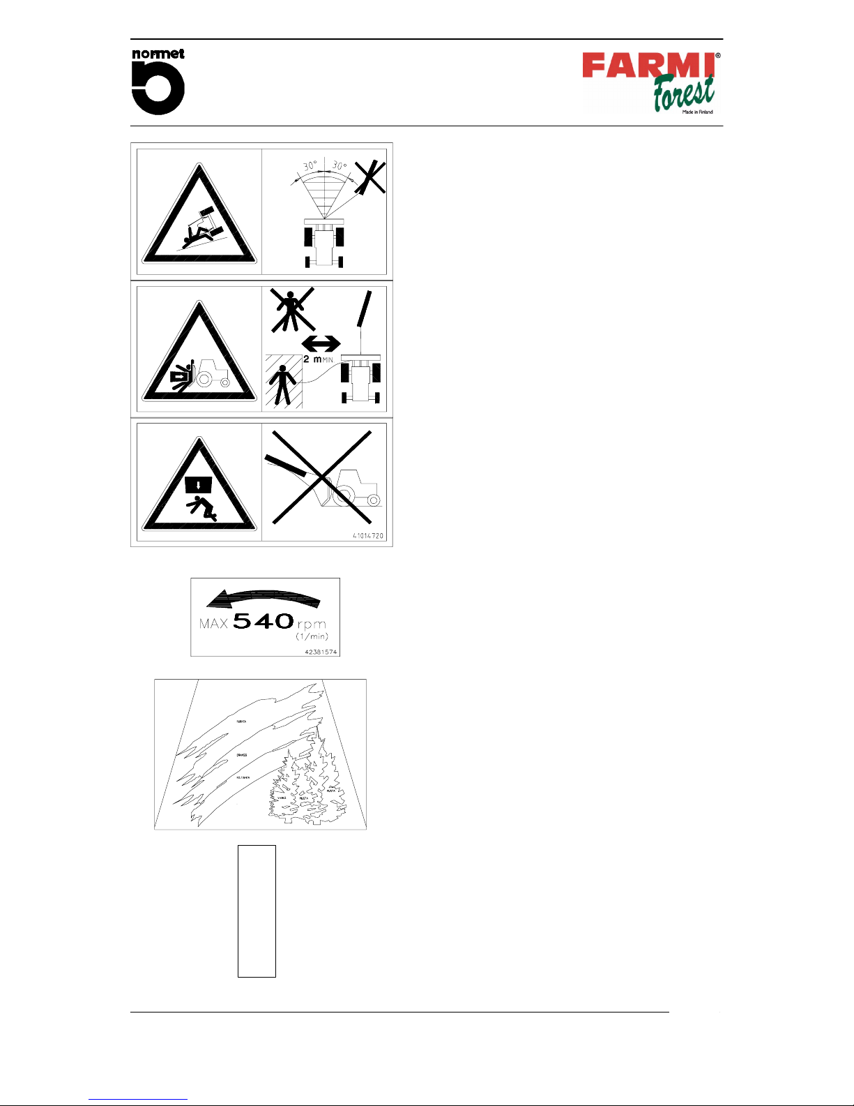
STICKERS AND SIGNS 7...............................................
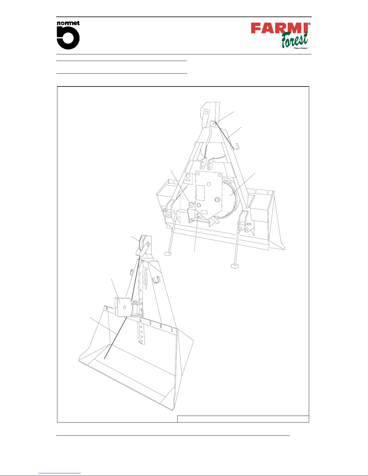
1. MAIN PARTS AND ACCESSORIES 10...................................
2. TECHNICAL DATA 11..................................................
3. DIMENSIONS 11.......................................................
4. MOUNTING INSTRUCTIONS 12.........................................
4.1. MOUNTING TO THE 3---POINT HITCH 12...........................................
4.2. ASSEMBLY OF THE PTO SHAFT 12...............................................
4.3. SHORTENING THE PTO SHAFT 12................................................
4.4. FASTENING THE CABLE TO THE DRUM 13........................................
5. PRE---OPERATION CHECKS 13.........................................
CABLE 13..........................................................................
Check that: 13......................................................................
WINCH: 13..........................................................................
Check that: 13......................................................................
MOUNTING TO THE TRACTOR 13.....................................................
Check that: 13......................................................................
6. CONTROLS 14........................................................
6.1. PULLING OUT THE CABLE 14....................................................
6.2. WINCHING 14..................................................................
7. OPERATION 14........................................................
7.1. SAFETY PRECAUTIONS 14.......................................................
7.2. PRE--- OPERATION CHECKS 15...................................................
MOUNTING AND USE OF THE LOWER SNATCHBLOCK 16...............................
7.3. WINCHING 16..................................................................
7.4. SKIDDING 16...................................................................
WORKING IN ROUGH TERRAIN: 17....................................................
IF YOU GET STUCK WITH THE TRACTOR: 17...........................................
7.5. DROPPING THE LOAD 17........................................................
7.6. TRANSPORTATION 17...........................................................
8. SAFETY 18............................................................
9. LUBRICATION 18......................................................
10. SERVICE 18...........................................................
10.1. CLUTCH ADJUSTMENT 18......................................................
10.2. ADJUSTING THE ROLLER CHAI TIGHTNESS 19...................................
10.3. ADJUSTING THE DRUM BRAKE 19..............................................
10.4. REMOVING THE WINCH MECHANISM 19.........................................
10.5. REASSEMBLING THE WINCH MECHANISM 20....................................
11. ORDERING OF SPARE PARTS 21.......................................
12. TROUBLE SHOOTING 21...............................................
SPARE PARTS 22.........................................................

SAFETY INSTRUCTIONS
JL 601
B // En // 141001 MRu
www.normet.fi
Normet Corporation
Ahmolantie 6
FIN ---74510 PELTOSALMI
FINLAND
Tel. + 358 (0) 17 83 241
Fa
x
. + 358
(
0
)
17 823 606
5Page
Do not use the winch, before you have read and understood the
manual! The owner is responsible for the guidance of all
persons, who have to deal with the device.
Do not use or service the winch before the becoming acquainted
with it.
WARNING!
D
DD
DOnly skilled persons may use and service the winch.
D
DD
DThe winch must always be checked before use and at least once a day the
safety conditionsand the possible faults must be checked.
D
DD
DCheck the moving parts. They have to be fastened to their places and in
good condition. All the protections and the limiters have to be in places.
D
DD
DThe winch must not be used even partly, without the protection parts.
D
DD
DWhen winching to downhill, the winch must be pulled from the side through
an extra snatchblock.
D
DD
DIt is perilous to be in the area between a load connected to the cable and a
winch.
D
DD
DBefore using the winch get acquainted with the controllers of the winch, test
the stopping functions of the winch and of the tractor and all the other
functions. Each function has to be in perfect order.
D
DD
DCheck that the winch is free of rubbish and other obstructions.
D
DD
DCheck that all the outsiders are in a safe area, at a distance of at least 15
metres, from the running machine. Warning signs must be installed in the
area of approaching roads .
D
DD
DThe cable must not be touched during winching with the hands.
D
DD
DWhen the winch is used on slopes, the load must not be followed from
below.
D
DD
DThe maximum load must be adapted to respective conditions.
D
DD
DCheck that the moving chains are carefully fastened. The cable must not be
coupled directly to the load.
D
DD
DThe safety factor must be 2.5 for cable type couplings and 2 for chain type
couplings.
D
DD
DInform all skidding winch users about the dangers and how they can be
avoided.
D
DD
DThe skidding winch may be operated only if it is attached to a tractor.
D
DD
DThe winch has to be fastened to 3--point hitch of the tractor. Defective
fastening may cause a dangerous situation.
D
DD
DDo not let children or incapable persons operate the winch.

SAFETY INSTRUCTIONS
JL 601
B // En // 141001 MRu
www.normet.fi
Normet Corporation
Ahmolantie 6
FIN ---74510 PELTOSALMI
FINLAND
Tel. + 358 (0) 17 83 241
Fa
x
. + 358
(
0
)
17 823 606
6Page
D
DD
DDo not wear loose clothing, loose sleeves or scarves around moving parts
of machinery. Long hair must be kept under helmet or cap!
D
DD
DMake sure that others are not in danger when you use the winch.
D
DD
DDo not leave the tractor running unattended.
D
DD
DDisengage the P.T.O and turn the tractor off before you service the winch.
D
DD
DRemove keys from the tractor so that it cannot be started up accidentally.
D
DD
DUse only original FARMI--spare parts replacements. Do not make any
modifications.
D
DD
DStay alert! Do not use the winch, if you are tired or under drugs.
D
DD
DIf you want to recover operational errors, the power transmission must be
switched off.
DWith running engine it is to be made certain absolutely that no part of the
body is in the area of the winch.
D
DD
DMake sure that the cable is in good condition before using of the winch
(corrosion, sharp bends, the breaking of strands and thickness). The cable
can fly towards the user when breaking or away from the winch.
D
DD
DNever handle cable without first shutting off the power take--off!
D
DD
DKeep the cable as short as possible during transportation.
D
DD
DUse the winch only for winching or skidding. Do not use the winch for lifting
loads.
D
DD
DPark the winch and tractor on level ground for winching.
D
DD
DOperate the winch from a control rope from at least 2m(6ft) to the side of the
machine. Do not operate the winch from the tractor seat if there is no
protective shield between the seat and the winch.
D
DD
DDo not winch at sideways at angles exceeding 30 degrees.
D
DD
DThe user must have a helmet, safety boots and the gloves which are
suitable for the handling of the steel cable.

STICKERS AND SIGNS
JL 601
B // En // 141001 MRu
www.normet.fi
Normet Corporation
Ahmolantie 6
FIN ---74510 PELTOSALMI
FINLAND
Tel. + 358 (0) 17 83 241
Fa
x
. + 358
(
0
)
17 823 606
7Page
4, 5, 6
2
13
10, 11, 12
1
7, 8, 9
14
15
3
Fig. 1. Machine plate
Fig. 2. Note!
See manual for operation and
maintenance.

STICKERS AND SIGNS
JL 601
B // En // 141001 MRu
www.normet.fi
Normet Corporation
Ahmolantie 6
FIN ---74510 PELTOSALMI
FINLAND
Tel. + 358 (0) 17 83 241
Fa
x
. + 358
(
0
)
17 823 606
8Page
Fig. 3. Falling danger!
Do not work in an oblique position.
Fig. 4. Crushing danger!
Do not use the winch for the lifting.
Fig. 5. Watch out for a breaking cable!
Always use the protective screen.
Fig. 6. Note!
Before doing maintenance work turn
off the motor, remove the ignition key
and disengage the P.T.O.
Fig. 7. Accident danger!
Keep the safety equipment where it
belongs.
Fig. 8. Winding danger!
Do not wear too loose clothes and
keep the hair bound inside the cap.

STICKERS AND SIGNS
JL 601
B // En // 141001 MRu
www.normet.fi
Normet Corporation
Ahmolantie 6
FIN ---74510 PELTOSALMI
FINLAND
Tel. + 358 (0) 17 83 241
Fa
x
. + 358
(
0
)
17 823 606
9Page
F
A
R
M
I
43402070
30730501
Fig. 9. Falling danger!
Do not winch at sideways angles
exceeding 30 degrees.
Fig. 10. Crushing danger!
Do not stand in front of the winch
when working. Stand on the side at a
distance of at least 6ft from the
winch.
Fig. 11. Crushing danger!
Do not winch downhill.
Fig. 12. Maximum rpm.
Fig. 13. METSÄ--sticker.
Fig. 14. FARMI--sticker.

TECHNICAL SPECIFICATION
JL 601
B // En // 141001 MRu
www.normet.fi
Normet Corporation
Ahmolantie 6
FIN ---74510 PELTOSALMI
FINLAND
Tel. + 358 (0) 17 83 241
Fa
x
. + 358
(
0
)
17 823 606
10Page
1. MAIN PARTS AND ACCESSORIES
Drum
Clutch
lever
Drive shaft
Control rope
Cable
(optional)
Upper snatchblock
Lower
snatchblock
(optional)
Pulley
ACCESSORIES ARE SEPARATELY SPECIFIED.
Fig. 15. JL 601 Main parts and accessories.

TECHNICAL SPECIFICATION
JL 601
B // En // 141001 MRu
www.normet.fi
Normet Corporation
Ahmolantie 6
FIN ---74510 PELTOSALMI
FINLAND
Tel. + 358 (0) 17 83 241
Fa
x
. + 358
(
0
)
17 823 606
11Page
2. TECHNICAL SPECIFICATIONS
JL 601
Tractive power Cable drum empty (Maximum) 60 kN
p
p
y
(
)
Cable drum full (Minimum) 27 kN
Cable capacity
Ultimate strength of the cable (recommendation)
96.0 kN/mm
2
130m of Æ10mm (426ft of 6/16”) cable
100m of Æ12mm (328ft of 15/32”) cable
60m of Æ14mm (196ft of 9/16”) cable
Winching speed 350
r
/
min
540
r
/
min
0.5 6--1.26
m
/
s
(1.87--4.1ft/s)
Shipping weight( without cable) 390 kg (859lbs)
Clutch
Mechanical friction plate clutch with heat sink
Power transmission Universal shaft from tractor
Mounting To 3--point hitch(Kat.II)
Power needed min. 45 kW (60 HP)
3. DIMENSIONS
JL 601
800--1040
460
750
1770
1800
2320
900
Fig. 16. Dimensional drawing of JL 601.

MOUNTING INSTRUCTIONS
JL 601
B // En // 141001MRu
www.normet.fi
Normet Corporation
Ahmolantie 6
FIN ---74510 PELTOSALMI
FINLAND
Tel. + 358 (0) 17 83 241
Fa
x
. + 358
(
0
)
17 823 606
12Page
4. MOUNTING INSTRUCTIONS
4.1. MOUNTING TO THE
3--POINT HITCH
The winch can be mounted to the 3---point
linkage of any tractor. Power transmission is
obtained through universal shaft from tractor.
4.2. ASSEMBLY OF THE PTO SHAFT
If the PTO shaft is too long it
may get pressed when the
three point hitch is lifted up.
This may cause damage to the
bearings of the winch or to the
PTO of the tractor. The PTO
shaft must not be too short in
any position. The PTO length
is suitable, if the pipes do not
reach the bottom. PTO is
optional equipment.
Note!
1. Mount the winch to the 3---point hitch of
the tractor.
2. Raise the winch high enough to get the
PTO shaft of the tractor and the winch to a
horizontal level.
3. If you have a shortened PTO shaft
available, put one end into the drive shaft
and check that the distance of the locking
of the other end. Take into account the
additional clearance of approx. 20
mm(0.78”).
4. Fasten the other end of the PTO shaft in its
place and also move the winch sideways
atthesametimesecuringthattheaxis
does not base.
4.3. SHORTEN THE DRIVE SHAFT
Both PTO halves must be
shortened by equal amounts.
PTO is optional equipment.
Note!
A
Fig. 17.Measure A when the drive shafts are
nearest to each other.
A
20
12
Fig. 18.Shorten the drive shaft.
DFirst cut the thicker cover to a correct
lenght (1). Remember 20mm (0.78”)
clearance. Then cut away the same
amount from the form pipe. Make a similar
shortening to the second half of the PTO
shaft. Remove the burr with the file.
DConnect the PTO shafts within each other.
Make sure by moving eevator carefully up
and down that the shortening of the axis is
sufficient. Check that the axis have 20mm
(0.78”) latitude.

MOUNTING INSTRUCTIONS
JL 601
B // En // 141001MRu
www.normet.fi
Normet Corporation
Ahmolantie 6
FIN ---74510 PELTOSALMI
FINLAND
Tel. + 358 (0) 17 83 241
Fa
x
. + 358
(
0
)
17 823 606
13Page
4.4. FASTENING THE CABLE TO THE
DRUM
1. Tape the cable end to prevent loosening of
the core wires.
2. Pass the cable through the hole in cable
guard, over the upper snatch block and
then inside the winch.
3. Insert the cable from behind the roll of the
drum brake.
4. Pull the cable onto the drum from the left
hand side (the same side as the clutch
lever).
5. Pass the cable end through the hole in the
drum plate, pull about 15 cm (6”), and
insert under the wedge of the cable lock
device. See fig. 19.
6. Tighten the cable lock screw.
7. Winch the cable on the drum. BUT
REMEMBER THAT THE CABLE HAS TO
BE LOADED HEAVILY, WHEN
WINCHING THE CABLE BACK ON THE
DRUM.
Fig. 19.Fastening the cable.
Do not use longer cable than needed. With
correct length you achieve good pulling
strength and proper winding of the cable.
5. PRE--OPERATION CHECKS
CABLE
Check that:
DThe cable is faultless (breakage risk).
DThere are no twists or kinks (breakage risk)
in the cable.
Dthe cable has been properly fastened to the
winch.
WINCH
Check that:
DAll the pins and lynch pins are in place.
DAll bolts and nuts have been tightened.
DRoller chain is tight.
DThe drum brake has been properly
adjusted.
DThe clutch has been correctly adjusted.
DLubrication is carried out correctly. See
lubricating instructions.
MOUNTING TO THE TRACTOR
Check that:
DThe tractor’s top link point is locked. (with
the help of a support, if necessary).
DThe pins are properly secured.
DThe sway bars or turnbuckles are suitably
tight.
DThe PTO--shaft is suitably long, properly
fastened and the shield chains attached.
DThe support leg of the winch is turned
upward.

OPERATION INSTRUCTIONS
JL 601
B // En // 141001 MRu
www.normet.fi
Normet Corporation
Ahmolantie 6
FIN ---74510 PELTOSALMI
FINLAND
Tel. + 358 (0) 17 83 241
Fa
x
. + 358
(
0
)
17 823 606
14Page
6. CONTROLS
Get acquainted with the
controllers of the winch before
the use, tests the stopping
functions of the winch and the
tractor and all other functions.
Each function has to be in
perfect condition.
WARNING!
6.1. PULLING OUT THE CABLE
DThecablecanbefreelydrawnoutifthe
drum has not been locked with a latch.
6.2. WINCHING
DThe winch is equipped with a clutch,
which will be used by the control rope.
When the user draws the control rope, the
winch begings to draw in the cable.
Winching will stop when the rope is
released.
DThe end of the cable drum is equipped
with a friction clutch, which slips, if the
load is too heavy. This prevents cable
break or damages if the load gets caught.
Control rope
Latch rope
Fig. 20. Controls
7. OPERATION
7.1. SAFETY PRECAUTIONS
Read the ope
r
ation
instructions before operating
this machine! It is the owner’s
responsibility to instruct all
equipment operators and
support personnel in the
operation of this winch.
WARNING!
1. Choose a horizontal, hard based skidding
route for the tractor. Avoid steep slopes,
especially when winching from the side.
Check that the winching trail is clear and
that the tractor’s parking brake is on. Do
not run the tractor at a high idle when
winching. Maximum P.T.O speed is 540
rpm. Ensure that the logs can be drawn
freely. Be especially careful when working
on slopes. Avoid winching sideways at
angles exceeding 30 degrees. Use
snatchblock which is fastened to the tree if
needed. (See fig. 23.)
2. The safest place for the operator is at the
back left side of the winch, allowing good
visibility. See fig. 21. Take care that there is
no one in the working area.
3. The tractor must have a ROPS cab and
front end weights.
DAlways position the tractor on a flat ground
in line with the direction of the pull (see
fig. 21.). Avoid working in steep terrain.
Ensure nothing is blocking the path of
trees.
DAvoid an unnecessarily strong pulls, the
tractor may roll over.
DAdjust the tractors rpm’s according to the
conditions.
DUse a shield between the seat and the
winch (e.g. safety cab or protective
screen) if you run the winch from the
tractor seat.
DUse agreed signals when working in
groups.
4. When you use a light tractor, there is a
very big risk that the tractor will roll over.
To avoid that risk, you must add extra
weight to the front of the tractor.

OPERATION INSTRUCTIONS
JL 601
B // En // 141001 MRu
www.normet.fi
Normet Corporation
Ahmolantie 6
FIN ---74510 PELTOSALMI
FINLAND
Tel. + 358 (0) 17 83 241
Fa
x
. + 358
(
0
)
17 823 606
15Page
DThe falling danger of the tractor can be
reduced by winching through the lower
snatchblock.
Fig. 21.
Fig. 22. Do not winch sideways at angles
exceeding 30 degrees. The tractor can tilt.
Fig. 23. Use a snatchblock to avoid winching
sideways.
7.2. PRE--OPERATION CHECKS
MOUNTING AND USE OF THE LOWER
SNATCHBLOCK
DUsually the logs are winched in through
the upper pulley of the winch. This lifts the
logs and they dig less into the ground. The
weight of the load also pushes the blade
into the ground thus anchoring the winch
and the tractor to the ground.
DThe winch has a lower snatchblock. The
main use of the lower snatchblock is to
lower the pulling point. This enables larger
loads to be skidded out . For skidding out
the load the cable is transferred to the
lower snatchblock.
DSeveral logs can be hooked up and
winched in at one time by means of
keyhole sliders on the cable. The skidding
chain should have a pin on the end, which
makesiteasiertopassthechain
underneath the tree. See fig. 24.
When using the lower snatch
blockmakesurethatitfollows
the direction of the cable.
Otherwise the cable will be
damaged, when it is pressed
between the snatch block and
the lower snatchblock frame.
NOTE!
When wInching an unloaded
cable, make sure that the
finger guard doesn’t rise up
with cable and doesn’t cause
cable to crosscut.
NOTE!
Fig. 24. Use a keyhole sliders to winch
several logs at one time.

OPERATION INSTRUCTIONS
JL 601
B // En // 141001 MRu
www.normet.fi
Normet Corporation
Ahmolantie 6
FIN ---74510 PELTOSALMI
FINLAND
Tel. + 358 (0) 17 83 241
Fa
x
. + 358
(
0
)
17 823 606
16Page
7.3. WINCHING
Before using the winch, you
have to pull the cable
completely out of the drum
and winch the cable back on
the drum with a heavy load.
Otherwise the cable will be
damaged.
NOTE!
DPark the winch and tractor on level, stable
ground. Lock the brakes of the tractor
before winching. Lower the 3--point hitch so
that the dozer blade anchors the winch to
the ground. See fig. 25.
Do not let the dozer blade sink
too deeply into the ground, so
that the PTO shaft is not
damaged
NOTE!
DBefore using the skidding winch, make
sure that the lower snatch block, the upper
snatch block and the finger guard move
freely.
Fig. 25. Anchor the dozer blade to the
ground.
1. Draw the cable to the load but avoid
twitches. Do not draw out too much cable
to avoid loose spaces when the cable is
reeled in.
2. Start the tractor, turn the PTO on. Use the
winch with the control rope and stand in a
safe place at a distance of at least 2m (6ft)
from the winch. Use the upper snatchblock
when winching.
3. Operate the clutch firmly. Avoid sliding the
clutch to avoid warming of the clutch. Stop
winching by letting go of the control rope
for the leave. The clutch will slip when the
load is heavier than the selected pull. This
prevents damages to the cable or winch.
Avoid extra large loads. The winding speed
depends on the number of revolutions of
the tractor. Do not wind too fast.
4. Stop winching when the logs are at about
1,5--3 m (5--10 ft) from the tractor. Install
the cable on the lower snatch block.
Fig. 26. Winching over the upper snatchblock
7.4. SKIDDING
Fig. 27. Cable on the lower snatchblock
1. Turn the P.T.O on. Pull the clutch control
rope and winch the logs to the pulley. Keep
the tension on the cable and pull the
thinner rope that operates the brake
ratchet. Stop pulling on the clutch rope first.
The load is now locked in place.
Alternatively the skidding chains can be
attached to the notched beam.
2. Turn off the P.T.O.
3. Raise the 3--point hitch so that the logs
come off ground (fig. 28.).
4. Move the logs to the desired place.

OPERATION INSTRUCTIONS
JL 601
B // En // 141001 MRu
www.normet.fi
Normet Corporation
Ahmolantie 6
FIN ---74510 PELTOSALMI
FINLAND
Tel. + 358 (0) 17 83 241
Fa
x
. + 358
(
0
)
17 823 606
17Page
Fig. 28. Winching over the lower snatch
block.
WORKING IN ROUGH TERRAIN:
Drop the load before you reach bad terrain.
Drive through the bad spot. Winch in the load
again (Fig. 29.)
WRONG
RIGHT
Fig. 29. Driving through bad terrain.
IF YOU GET STUCK WITH THE TRACTOR:
1. Drop the load. Drive the tractor to firm
ground. Winch in the load.
2. If you cannot move the tractor, release the
load and winch the tractor out. When
winching the tractor out, always run the
cable under the lower pulley.
Fig. 30. Winching the tractor out.
7.5. DROPPING THE LOAD
1. Let down the 3--point hitch.
2. Pull the clutch rope until the brake ratchet
releases, then stop pulling the clutch rope.
The logs drop to the ground.
7.6. TRANSPORTATION
The cable should be run under lower
snatchblock and locked in place for
transportation of the winch.

MAINTENANCE, LUBRICATION AND
ADJUSTMENT INSTRUCTIONS
JL 601
B // En // 141001MRu
www.normet.fi
Normet Corporation
Ahmolantie 6
FIN ---74510 PELTOSALMI
FINLAND
Tel. + 358 (0) 17 83 241
Fa
x
. + 358
(
0
)
17 823 606
18Page
8. SAFETY
Disengage the P.T.O and turn
the tractor off before you
service the winch, remove the
keys so the tractor cannot be
sta
r
ted up accidentally.
DANGER!
9. LUBRICATION
Do not oil the drive chain,
because the oil will work its
way to the clutch!
NOTE!
The cable drum, main sprocket and
snatchblock are fitted with self lubricating
bearings.
Following points require lubrication:
1. Grease the drum clutch parts after every
500 working hours. Always use good
quality lubrication grease.
2. Grease the PTO---shaft regularly and
aways before use as shown in figure 31.
3. Grease the drum chain lightly (not with oil)
after every 50 working hours with spray type
, hardening chain grease. Wipe off the
excessive grease.
Swing joints sideways for greasing
8h 8h
h= working hours
20h
Apply grease inside the
outer telescopic profile
When used in winter the
guard tubes must be grea-
sed to avoid freezing.
Fig. 31. P.T.O shaft lubrication.
10. SERVICE
10.1. CLUTCH ADJUSTMENT
1. Loosen the nuts A and B at both ends of
the drum axle. Wrench opening 1
7
/
16
”(36
mm).
2. Adjust the clutch by turning the axle C with
9
/
16
” or 14 mm wrench. The clutch
tightens clockwise, loosens
counterclockwise. Turn max. 1/4 turn.
3. After adjustment retighten the nuts A and
B on the ends of the drum axle.
4. Pull the control rope. The lever should
move up 1.5” (4cm) before the clutch
engages. If the clutch engages earlier
loosen the clutch setting.
ABC
Fig. 32. Clutch adjustment.

MAINTENANCE, LUBRICATION AND
ADJUSTMENT INSTRUCTIONS
JL 601
B // En // 141001MRu
www.normet.fi
Normet Corporation
Ahmolantie 6
FIN ---74510 PELTOSALMI
FINLAND
Tel. + 358 (0) 17 83 241
Fa
x
. + 358
(
0
)
17 823 606
19Page
10.2. ADJUSTING THE ROLLER
CHAIN TIGHTNESS
Roller chains tightness adjustment is carried
out by moving the chain tightener. See fig. 33.
1. Loosen the two bolts holding the chain
tightener (11/16” or 17mm wrench).
2. Adjust the chain tightness by moving the
chain tightener towards or away from
center.
3. Tighten the nuts.
4. Check that the chain tightener runs on the
rollers.
NOTE! Do not over tighten the chain.
Tighten
Loosen
Fig. 33. Tightening the roller chain.
10.3. ADJUSTING THE DRUM BRAKE
Adjust the drum brake so that it slows down
the drum slightly while pulling out the rope.
This will reduce risk of tangling and backlash.
DTo increase the braking effect tighten the
adjustment bolt. See fig 34. To decrease
the braking effect loosen the adjustment
bolt.
Friction piece
Drum brake adjustment bolt
Lock nut
Fig. 34. Drum brake adjustment.
10.4. REMOVING THE WINCH
MECHANISM
The whole winch mechanism can be removed
in one piece from the frame. To remove the
winch mechanism from the winch (e.g. in order
to change the roller chain) follow the
instructions below:
1. Park the winch on a level, stable ground
so that it leans a little backwards.
2. Remove the cable.
3. Remove the fastening bolts (fig. 35 pos. B)
beside the drive shaft. Socket size 24mm
(
15
/
16
”).
4. Remove the two bolts (fig. 35 pos. A)at
the upper edge of the cover plate. Socket
size 24mm (
15
/
16
”).
5. Removethedrumaxlenut(fig.35pos.C)
andthewasher.Socketsize36mm
(1
7
/
16
”)
6. Pull out the winch mechanism.
Weight 243 lbs (110 kg).
A
B
C
Fig. 35. Removing the winch mechanism.

MAINTENANCE, LUBRICATION AND
ADJUSTMENT INSTRUCTIONS
JL 601
B // En // 141001MRu
www.normet.fi
Normet Corporation
Ahmolantie 6
FIN ---74510 PELTOSALMI
FINLAND
Tel. + 358 (0) 17 83 241
Fa
x
. + 358
(
0
)
17 823 606
20Page
10.5. ASSEMBLY OF THE MECHANISM
Make sure that the both pressure bearings are
installed in a correct position, that is, the
bearing with bigger internal diameter should be
facing the cable drum (figure 37). Make sure
that the position of the two clutch engagement
halves is correct:
1. Place one of the clutch engagement
halves on the working tble so that the
handle is at 8 o’clock position and the 3
slanted surfaces face up. See fig.36.
2. Grease the 3 slanted surfaces with
vaseline and place the 3 rollers on the
bottom of the slanted surfaces so that the
thin ends point towards the middle.
The other clutch engagement half (without
handle) has 3 slanted surfaces on one side
and two holes drilled on the other side (fig 36).
Two studs on the back of the front plate will fit
into these holes later on when the winch is
assembled.
3. Place one clutch engagement half (without
the handle) so that the halves bottom out
when the handle is at 8 o’clock position
and the two holes are at 12 o’clock and 6
o’clock (fig. 36). Be careful, there is only
one correct position! Tape the halves
together so that htey will stay together
when you mount them on the drum axle.
Install a protective plate. Check the clutch
adjustment.
12
6
8
12
6
12
6
8
a)
b)
c)
Fig. 36. Reassembling of the clutch
engagement halves.
Drum
Drum axle
Main Sprocket
Theracewiththelarger
inside diameter is towards
the drum
The race with the larger
inside diameter is towards
the drum
Race with smaller inside diameter
Race with larger inside diameter
Clutch engagement half
Roller
Clutch engagement half
Fig. 37. Correct positioning of the thrust bearings.
11. ORDER SPARE PARTS
When ordering spare parts, please refer to your machines type code on the name plate and to the
spare parts lists order number, description and quantity desired.
JL 601, 54511340, Bearing, 1 pc.
Table of contents
Other Farmi Forest Corporation Winch manuals
Popular Winch manuals by other brands

Tractel
Tractel Carol EX 150 Installation, operating and maintenance manual

goldwinch
goldwinch GW 4000 T 2S Service manual

Dover
Dover TWG TULSA WINCH 707W Service manual

Conveying & Hoisting Solutions
Conveying & Hoisting Solutions Star Installation and operating instructions

Cub Cadet
Cub Cadet 39A70048100 installation guide

BRADEN
BRADEN HP100B Installation maintenance and service manual