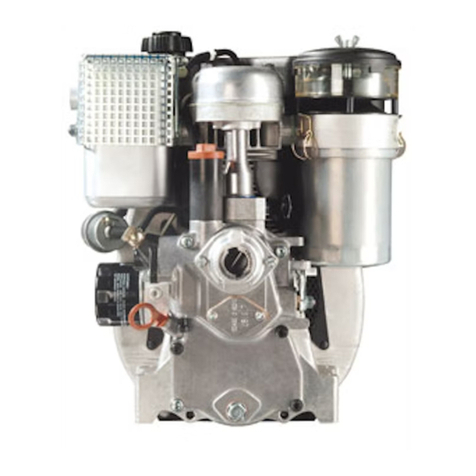
Farymann Diesel 15D Series Instruction manual

3
CONTENTS
IGeneral Information
I.1. Introduction 5
I.2. Farymann Diesel engines 7
I.3. Engine identification 7-8
I.4. Cross reference old - new engine type 8
II Technical Data
II.1. General engine data 9
II.2. Picture of model 15/18 10
II.3. Sectional view of model 15/18 11
II.4. Special tools 12-14
III Engine Repair
III.1. Engine disassembly 15-27
III.2. Wear and tear measurements 28-41
III.3. Engine reassembly 42-58
III.4. Lubrication system 59
III.5. Function and repair of fuel system60-65
III.6. Governor 66-70
III.7. Resurfacing of valve seats 70
III.8. Setting datas for fuel timing 71-72
III.9. Tightening torques 73
IV Trouble Shooting 74-78

4
PREFACE
This Manual is for workshop use only and intended for use by experienced
mechanics.
Only the standard type of engine models 15B/D 18B/D 29C/32A are illustrated and
dealt with.
Because there are, however, many different type variants which can differ to a greater
or lesser degree from the standard type described, this Manual can and should be
used only as a quideline. Because some work is very complicated, we recommend
that the Manual be completely read before starting repairs.
The repair of FARYMANN DIESEL engines requires some special tools in addition to
standart ones. Their use is strongly recommended.
All safety precautions are to be strictly observed, because otherwise:
- death or injury to the user or third parties can occur;
- the machine or other material assets of the user may be impaired;
- efficient operation of the machine may be jeopardized.
Every person in the user`s business who is tasked with the installation,
commissioning, operation, servicing or repair of engine must have read and
understood the „Safety“ chapter of the Operating Instructions.
The engine may be serviced only by trained personnel. Any work procedure which
impairs the saety of the engine is to be forbidden.
Modifications or changes to the engine or the use of non-original replacement parts
without proper authority is not allowed on safety grounds and invalidates the liability of
the FARYMANN DIESEL COMPANY.
This Workshop Manual is technically up-to-date at the time of poing to press. Every
care was taken in its compilation to avoid errors.
We are, however, not responible for any errors in illustrations or descriptions or for any
omissions. There may also be changes due to technical developments.
We reserve the right to make changes without prior notice
.

5
I.1. Introduction to Diesel Engines
Nowadays diesel engines are well known and quite common in all kinds of machinery and
equipement as an alternative to the well established gasoline engine.
Most people who are fully familiar with gasoline engines are reluctant to deal with a Diesel. This
is without any reason, in fact, you already know more about a Diesel than you may have
thought. If you are already familiar with the gasoline 4-stroke engine, study the comparison
below. It will show the differences between a 4-stroke Diesel and a 4-stroke gasoline engine.
Gasoline Diesel
I. Intake stroke
The downwards movement of the piston
draws a mixture of gaseous fuel and air
through the open inlet valve into the
cylinder.
II. Compression stroke
The upwards movement of the piston
compresses the fuel/air mixture. The
temperature rises through the
compression stays below the self-ignition
point of the fuel.
The downwards movement of the piston
draws only air through the open inlet valve
into the cylinder.
The upwards movement of the piston
compresses the air, which causes the
temperature to rise above 500 C (932 F).

I. GENERAL INFORMATION
6
III. Power stroke
A spark created by a spark plug ignites
the fuel. The resulting expansion of the
combustion gases forces the piston down.
Fuel in a fine mist is sprayed into the
cylinder and self ignites in the hot air. The
resulting expansion of the combustion
gases forces the piston down.
IV. Exhaust stroke
The upwards movement of the piston forces the exhaust gases through the open exhaust
valve. This stroke is identical on both engines.
Both engines are of the internal combustion design because they burn fuel within the engine.
Both engines require fuel, air and a method of igniting the fuel.
Both engines can be of 2 - or 4 cycle design.
Both engines can be aircooled or watercooled.
The basic differences are:
The gasoline engine has an external mixture (carburator) of the fuel and combustione air. It needs an
electric source (spark plug) to ignite the fuel.
The diesel engine draws in only air. It has an internal mixture of fuel and combustion air. The fuel is self-
ignited by the high temperature of the compressed air.
To ensure that the air temperature is high enough to ignite the fuel, a diesel engine has a very high
compression ratio compared to a gasoline engine. The diesel engine does not need an ignition system,
due to the self-ignition of the fuel. Needed are a injection pump, fuel lines and a fuel injector. The
injector is often called the heart of the diesel engine. It is a precision manufactured assembly, built to
rigid specifications and clearances. It performs almost the same duties as a carburator. An injection
pump delivers fuel to the injector where it is sprayed into the cylinder. Another difference between diesel
and gasoline engines is that a diesel engine does not use a throttle valve. The governing is done by
varing the amount of fuel injected into the cylinder.
Whereever sturdiness, reliablity, fuel economy and long service life are required, the diesel engine is the
right choice.

I. GENERAL INFORMATION
7
I.2. Farymann Diesel engine
All Farymann Diesel engines are 4 stroke, direct injection diesel engines. They are built as single
cylinder engines in vertical and horizontal cylinder configuration.The direct injection guarantees an
outstanding efficiency with low fuel consumption and excellent cold starting abilities. Robert Bosch fuel
injection equipments are used on all engines. A high precision centrifugal governor totally enclosed in
the crankcase links to the fuel injector pump and to the speed contol lever.
The flywheel fan cools the engine, eliminating troublesome V-belts. Air is drawn into the flywheel fan and
routed through shouding to the cooling fins of the cylinder head.
I.3. Engine identification
Until July 1982 the engine nomination system consisted of a 10 figure code.
For example: 35K54 0715 F
35 = code figure for the year of manufacture
K54 = engine type
0715 = serial number
F= code figure for month of manufacture
Effective July 1982 the new system consists of a 12 figure code system in addition to the serial
number (see engine name plate).
For example: 15D430 0118 D5
860320 = manufacturing date
15 D430 0118 D5
Trim-no. = engine speed and governor
Type-no. = engine specification
Starting 0 = manual crank start
system 1 = recoil starter
5 = electric starter
6 = manual crank start with alternator
7 = alternator with starter
Bearing 3 = roller bearing at flywheel side
Crankshaft 4 = horizontal crankshaft
Basic A = vertical cylinder configuration anti
Engine clockwise rotation (former execution)
Design B = vertical cylinder configuration
clockwise rotation (new execution)
D = vertical cylinder configuration
anti-clockwise rotation
E = horizontal cylinder configuration
anti-clockwise rotation
W = watercooled cylinder configuration
anti-clockwise rotation
Displacement in cubic inches

I. GENERAL INFORMATION
8
I.3. Engine identification
An engine name plate is affixed to every engine. In addition to the name plate the engine order
number and, effective July 1985, the running engine number are also stamped on the
crankcase.
The complete engine code must be quoted when ordering spare parts in order to supply the
correct parts for the engine.
I.4. Cross reference old - new engine type
up to 1982 since 1982
K54/15A model range 15D
K55 model range 15B
K64/18A/C model range 18D
K65 model range 18B
K34 model range 15W/18W

II. TECHNICAL DATA
9
II.1. General engine data
Specifications/engine type 15B/D 18B/D 29C 32A
______________________________________________________________________
Number of cylinders one, vertical
Combustion direct injection, 4 stroke
Bore/Stroke [mm] 75/55 82/55 90/74 95/74
Total displacement [cm3] 242 290 470 524
Compression ratio 1:20 1:20 1:19 1:20
______________________________________________________________________
Direction of rotation A+C+D: counter clockwise when viewed flywheel
B : clockwise when viewed flywheel
______________________________________________________________________
Performance data (full load)
Working speed, max. [min-1] 3600
Idle speed, min. [min-1] 900-1000
Output „A“ DIN 6270 [kW(Hp)] 3.5 (4.8) 4.2 (5.7) 6.6 (9) 7.1 ( 9.7)
„B“ DIN 6270 [kW(Hp)] 3.9 (5.3) 4.7 (6.4) 7.35(10) 7.9 (10.7)
„F“ DIN 70020 [kW(Hp)] 4.3 (5.8) 5.1 (6.9) 8.1 (11) 8.7 (11.8)
Mean piston speed [m/s] 6.6 6.6 8.88 8.88
Torque („F“ output) Nm/ min -1 12.5/2400 15.2/2500 24.5/2400 27.5/2400
Lub. oil pressure max. [bar] 4.0 4.0 5.0 5.0
(at 100°C (220°F) oil temp.)
Lub. oil pressure min. [bar] 1.8 1.8 2.0 2.0
(at 100°C (220°F) oil temp.)
Fuel consumption [g/kWh] 330 310 295 300
Lub. oil consumption [g/kWh] 1.0 1.0 1.0 1.0
Exhaust back
pressure max. [kPa] 5.0 5.0 5.0 5.0
Intake underpressure max. [kPa] 2.0 2.0 2.0 2.0
Operation temparatures
Lub. oil max. [°C(°F)] 130 (317) 130 (317) 130 (317) 130 (317)
Exhaust gas in
manifold max. [°C(°F)] 580 (1,415) 580 580 580
Entering cool. air max. [°C(°F)] 50 (122) 50 50 50
∆t cooling air
(at outlet cyl.-head) [°C(°F)] 50 (122) 50 50 50
Capacity
Lub. oil [dm3] 1.0 1.0 1.6 1.6
Fuel tank [dm3] 4.0 4.0 6.8 6.8
Weight
Engine (dry, standart,
flywheel) [kg] 39.5 39.2 70.5 70.0
Setting data
Valve clearance
cold engine [mm] 0.1 0.1 0.1 0.1
injection pressure [bar] 200 200 175 175
Working angle (standart oilpan)
lengthwise deg. 25 25 25 25
crosswise deg. 25 25 25 25
III.1. DISASSEMBLY
10

II. TECHNICAL DATA
11

II. TECHNICAL DATA
12
II.4. Special Tool List
It is assumes that authorized Farymann Diesel Dealers have all of the common tools needed
to service diesel engines i.e. metric open end and ring spanners, sockets, torque wrench, mtric
caliper and depth gauge as well as piston ring pliers, piston ring compressor, etc.
All “drivers“ should be used with a hydraulic or arbor press.
Part No. Description Use
748.092.2
748.093.2
748.094.2
748.116.6
Pin Allen Wrench 4mm
Pin Allen Wrench 5mm
Pin Allen Wrench 6mm
To remove pin type allen head screws
(only for old models of K5/K6 engines)
748.115.6 Fuel line camp To clamp fuel supply lines
748.117.6 Drip tube assembly To check injection timing
748.171.4 Hexagon Socket 14mm For gorvernor screw
748.170.4 Deep tube Socket 13mm For cylinder head nuts
748.130.2 ¾“ Drive Socket 36mm For flywheel nut
748.128.4 ¾“ Drive Sticker For use with socket
748.108.5 Governor spring tool To adjust governor spring tension

II. TECHNICAL DATA
15
13
748.132.6 Cranksh. Race Puller Use with puller to remove crankshaft
roller bearing race
748.137.2 Crankshaft Gear Puller Use with puller to remove crankshaft
gear wheel
748.136.2 Puller For parts 148.132.6 and 748.137.2
748.122.6 Flywheel Puller To remove flywheel from crankshaft
tapper
748.119.4 Bearing driver To install crankshaft roller bearing
outer race and radial oil sealing ring
748.120.4 Bearing Driver To remove and install crankshaft
bearing bushing and to remove
camshaft roller bearing
748.121.4 Bearing Driver To remove and install camshaft
748.124.4 Bearing Driver To remove crankshaft roller bearing
outer race and to install camshaft roller
bearing
748.173.2 Oilfilter Socket To remove oilfilter
748.172.4 Bearing Driver To remove and install conrod bearing
bushing

III. ENGINE REPAIR
14
748.129.4 Bearing Driver To remove and install regulation shaft
bushing
748.123.4 Bearing Driver Handle Treated handle for various bearing
drives
748.125.4 Valve Guide Driver To remove and install valve gides
748.131.5 Valve Sring Compr. To remove and install valves
748.135.2 Retaining Ring Pliers To remove retining rings
748.126.2 Oil Pressure Gauge To check engine oil pressure
748.127.4 Gauge Adaptor To connect oil pressure gauge at
crankcase
748.138.2 Valve reface kit 43 cutter to reface valve seats
748.174.4 Hilding device To tighten and remove governor of
partly assembled engine

II. TECHNICAL DATA
15
III.1. ENGINE DISASSEMBLY
Prior to dismantling the engine clean off
engine exterior thoroughly.Dismantling
will be greatlyfacilitated by location
withgood lighting and freedom
ofmovement, away from dirt andmetal
chips.The work to be carried out
isdescribed and illustrated step by step in
the following.Please do take the trouble to
read the description of thework involved
prior to startingso that the scope will
beappreciated right from the start.

III. ENGINE REPAIR
16
1. Drain lubrication oil
Place suitable container under the drain
hole. Remove oval flange of oil drain,
remove oilfilter. Wait until oil has fully
trained, if necessary, tip over engine.
(Figures 1 and 1a)
2.Air cleaner
Remove the two aircleaner selflocking nuts.
Pull off the air cleaner and discard gasked.
3. Muffler
Unscrew the two M8 hex nuts of the muffler
and the M6 hex nut of the muffler screen.
Pull of the screen, muffler and discard
gasket.
(Figure 2)
4. Fuel tank
Place clamp, close to the injector pump on
the fuel supply line coming from the tank.
Next, remove the banjo bolts and their
copper washers from the fuel injector and
the fuel injection pump. Close ports of
injector and pump again with banjo bolts to
preventdirt from entering. Next,remove the
locknut holding the fuel supply line clamp.
Finally, loosen the fuel tank straps and slide
them off the ends of the tank. The fuel tank
and the line may now be removed.
(Figure 3)


III.1. DISASSEMBLY
17
5. Fuel tank support brackets
Pull off the fuel tank upport
brackets as well as the intake and the
exhaust manifold gaskets.
Figure 4)
6. Air deflectors
Remove the two screws and lockwashers
holding the air deflector shields on top of the
crankcase.
(Figure 5)
7. Valve cover
Remove the valve cover and the gasket by
removing the two nuts and plastic washers
on top of the valve cover. If necessary, tap
lightly on the side of the valve cover with a
soft faced hammer to loosen it.
(Figure 6)
8. High pressure fuel line
Loosen the high pressure fuel line by holding
a 14 mm wrench on the delivery valve holder
while unscrewing the
fuel line fitting with a 17 mm wrench.
(Figure 7)

III. ENGINE REPAIR
18
Loosen the high pressure line at the injector
in the same way.
(Figure 8)
9. Fuel injector
Remove the two hex nuts and their
lockwashers from thr injector clamp. and pull
out the injector. If the injector sticks in the
hand, use a soft faced hammer and tap
slightly on the injector. Do not use too much
force, as this may damage the injector.
Attention: Undder the injector a special
packing washer is located which must
also be removed.
10. Cylinder head
Remove the two locknuts and washers (1)
holding the protection tubr retaining spring.
Next loosen the four cylinder head nuts (2).
(Figure 10)
Drive out the rocker arm bolt with a drift pin
and a hammer. Remove the rocker arms and
push rods.(Figure 11)

II. TECHNICAL DATA
19
Remove the cylinder head nuts and the
cylinder head.
(Figure 12)
For dismantling valves use special tool.
Watch out for the two thin steel washers
under the inlet valve spring.
(Figure 13)
If the valve guides need replacement (for
wear and tear measurements refer to section
III.2.),use driver to press old guides out.
(Figure 14)

III. ENGINE REPAIR
20
Shout the valve seat be damaged to the
point that grinding of valves is not sufficient,
the seat can be resurfaced with tool (for
wear and tear limits and detailed instructions
for use of tool refer to section III.2. resp.
III.7.)
(Figure 15)
11. Cylinder shields
Remove the bolt holding the two cylinder air
deflector shields together using a
screwdriver and needle nose pliers or a
seven mm wrench.
(Figure 16)
Next, unscrew the two head screws and
remove the shields from the crankcase.
(Figure 17)

II. TECHNICAL DATA
21
Compression release
After removing its screws, pull the
compression release out of the gearcase.
(Figure 18)
13. Cylinder
Rotate the flywheel until the piston reaches
the bottom of its stroke. Carefully slide the
cylinder up off the studs.
Attention: If the repair does not require
the renewal of piston and liner, leave the
liner on the piston. Pull up the liner only
so far that piston pin bore is free and
continue with step 14.
(Figure 19)
14. Piston
Slowly rotate the flywheel until the piston
reaches the top of its stroke. With a needle
nose pliers, remove the piston pin retainer
from groove in piston at the gear train side of
the engine.
(Figure 20)
This manual suits for next models
7
Table of contents
Other Farymann Diesel Engine manuals

Farymann Diesel
Farymann Diesel 15W Series Operating instructions

Farymann Diesel
Farymann Diesel 15W Series User manual

Farymann Diesel
Farymann Diesel 15B Series User manual

Farymann Diesel
Farymann Diesel 37E Operating instructions

Farymann Diesel
Farymann Diesel K Series Operating instructions

Farymann Diesel
Farymann Diesel L 30 User manual
Popular Engine manuals by other brands

Robin
Robin EY15 Service manual

Beckhoff
Beckhoff AX2090-L80 Series Assembly instructions

Crestron
Crestron DGE-100 product manual

Briggs & Stratton
Briggs & Stratton 120000 Operating and maintenance instructions

SCHUNK
SCHUNK STM 560V Series Assembly and operating manual

Yanmar
Yanmar 2TNV70-HGE General specification