Fasetech RacingCUBE User manual

To be able to ship the RacingCUBE effective and securely we need to disassemble a few parts for the
journey. Do not worry, it is quite simple, and we are providing you with the tools needed for
assembly. It should take 2 - 4 hours the first time you assemble it.
Place the rotation module bracket on the floor and slide the two plates together around it, as seen on
the picture. Attach the two brackets at each side of the connected plates and screw in the two screws
[P07]. This will hold the bracket in place.
Assembling the Simulator
Bolts can either be black or chrome. It depends on the model.
Assembling of the rotation plate.

It is recommended to find an object to slide under the base to lift it slightly. Once the simulator has
been lifted you can attach the rotation module, before sliding it into place make sure you attach the
cables. They should go through the hole showed in the picture. Use [P02] bolts on the side.
Step 1 – Place the rotation module in the slider as showed and connect the connectors, ensure
everything is tight and connected properly. The hole on the rotation module is quite small, it is to
ensure the cables will not get in the way for the actuators. (There is a hole for each cable on the
newest models).
Before assembling the rest of the simulator, it is recommended to place the rotation plate
where you intent to place it after assembling. Once you have found a good spot, place the
simulator base on the rotation plate and continue assembling.
Rotation Module

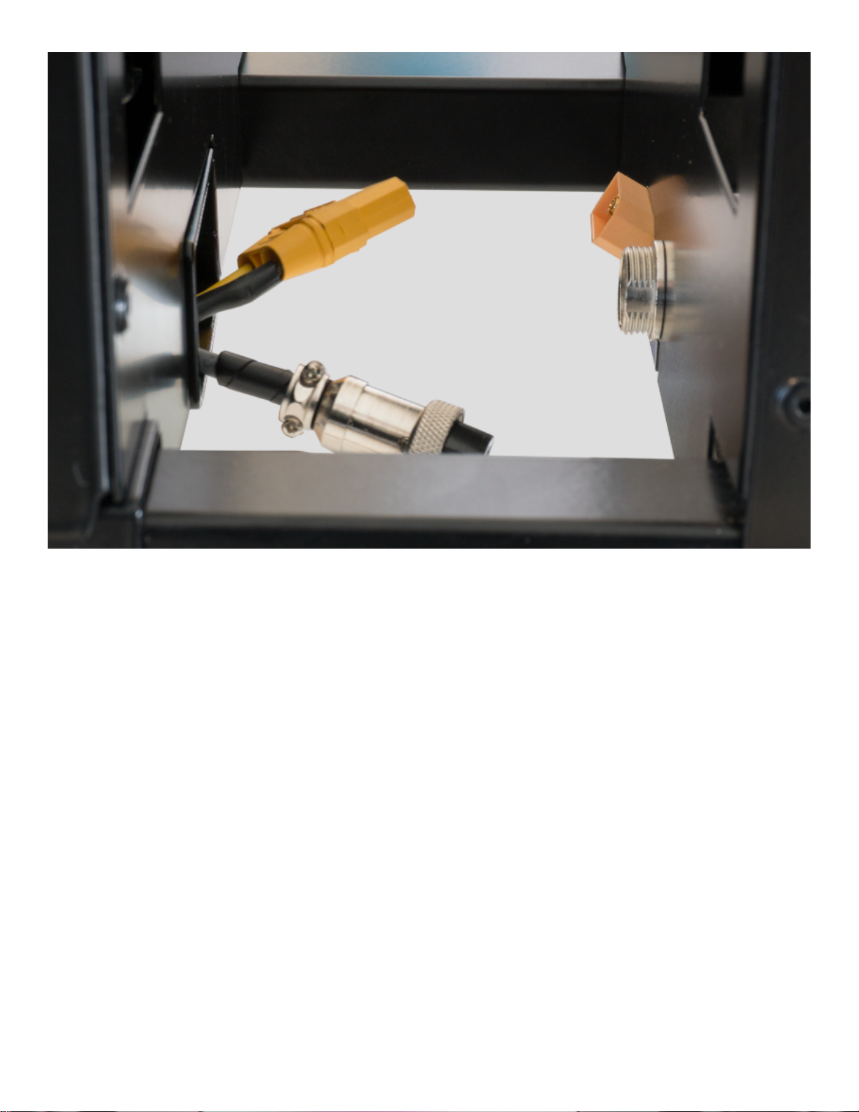
Step 2 – Manage the cables as shown on the picture. All connectors and cable should go into the
rotation module to ensure the main module is clear. You might need to get access to the simulator
from below to be able to attach the connectors. Make sure no cables will get run over or get in the
way of the actuators while in operation. (Use separate holes if present).

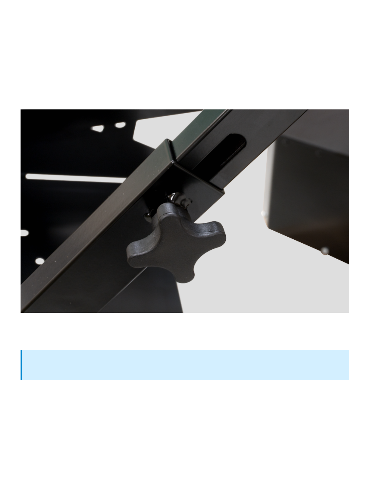
Use the provided hand knobs to fasten the V-Frame to the base. Make sure to fasten it enough to
prevent it from sliding while in use. The designated hole with a nut in it is designed for the thumb
screw or a 40mm bolt if you prefer.
The version depends on whether you have gotten one or two pairs of hand knobs. Please use
the correct item and make sure to tighten it properly.

To mount the foot support, you need the [P02] Bolts and the included brackets. Mount the bracket on
the foot support as showed on the picture above. Do not tighten the bolt and handle yet.
Once you have mounted the bracket you can slide the foot support into the V-Frame as showed
above, you can adjust the foot support to your liking by using the slide to the left where the bolt is
attached.

When you have found the desired placement for the foot support you can tighten the bolt and handle.
With the upgraded design of the RC4 v2 you can easily swap your foot support by loosening the
handle and slide it out. This way you can change from car pedals to rudder pedals in no time!
The steering wheel mount is quite easy to attach, just slide it into place and tighten the included
thumb screws [P13] or [P03] (Depending on configuration).
The bracket plate is used to mount the steering wheel on and is also used to slide it to the desired
position. Use [P06] [P09] [P10] to attach it to the frame.
Steering Wheel Mount
The AIO mount supports a variety of different manufactures. Please consult our FAQ page to
see if your equipment fits.

The seat slider supports most standard seats on the market. If you are unsure your seat fits, please
consult the manufacturer regarding mounting measurements. You can see ours on the image below.
Some configurations will have bolts included [P01] [P10].
Seat Mount
The bolts fastening the seat slider to the frame have NOT been tightened as you might have to
adjust to fit your seat.

As the simulator offers modularity and the use of your own gear, we cannot manage most of the
cables beforehand. Beneath the seat is plenty of room for excess cables and a power strip and maybe
an extra USB HUB if you need it. The management of cables to various places is usually done with
Velcro or zip ties depending on the location. On the website you can see pictures of how we manage
cable and to the left is a picture of the model without accessories for reference.
Finishing Assembly

To connect the simulator to your computer just plug in the long USB cable provided. Only one cable is
required to operate the simulator and it should go into the USB-B connector. The other two USB-A
connectors are for accessories of your choice. To proceed with the installation of the software please
continue with the SimTools Guide.
If you have bought a computer through our web shop, SimTools will be installed by default on the
computer. To connect SimTools to the simulator please run the Afterinstall.exe located on the
Desktop. By doing that you will assign the correct COM ports to the simulator. You can also do it
manually by following the SimTools Guide.
Connecting the PC
Connecting Pre-built PC's to the Simulator

The simulator works by lifting you with three actuators, in order to give you the best experience and
distribute the load it is important you balance the simulator. To balance it please use the different
methods of adjustments described further down in this guide.
The center of balance should be in the center of the three actuators, meaning there should no more
or less at the front or back of the simulator. A perfect balance can be hard to achieve and is not
necessary, but a relative balance will improve performance drastically. If multiple people with a big
difference in weight or weight distribution will be using the simulator, we recommend using the seat
slider and the slider with hand knobs at the lower frame.
Due to the unique design of the simulator and the actuators chosen for the platform, it needs to be
used for 10 – 20 hours before running completely smooth. You might encounter roughness and noises
from the gears within that time frame, however that is completely normal.
At the front of the Base Platform is a panel along with some different connectors. On the picture you
can see what the different connectors do and what to use them for.
Calibrating the Simulator Before First Use
First Use
Front Panel

1. Motion Display – The display goes from 0 – 9 and updates the force of the actuators LIVE. If
the display shows 0 it means no motion, 9 is max force based on the settings you have
made in the software.
2. Telemetry connection - USB-B to USB-A for connecting the simulator to your computer.
3. Accessory USB HUB – Use these USB ports to connect your accessories. (Only RC4v2)
4. Bass shaker power – Used for powering the amplifier for the bass shaker bought at our shop.
5. Left: Emergency stop connector. Right: Power connector – Used for powering the simulator
and connecting the emergency stop. The simulator cannot be used without the emergency
stop for security reasons.
Accessories bought from our shop is compatible with the RC4 simulator. Mounting is quite easy by
using the provided brackets; however, you can see how to attach it and adjust in the guides below.
This section will be updated when new accessories is added.
HOTAS mounts can be attached at the rail system on the side of the frame below the seat. It can be
adjusted to the full extent of the rail system, meaning you can slide it all the way back once not in
use. The rail system is used with the provided brackets. Use the [P03] bolts and the [P08] washers to
fasten it as showed on the picture. The brackets go inside of the steel bar, to fasten it easily mount it
from the rear of the simulator.
The Shifter mount can be attached at the rail system on the side of the frame below the seat. It can
be adjusted to the full extent of the rail system, meaning you can slide it all the way back once not in
use. The rail system is used with the provided brackets. Use the [P03] bolts and the [P08] washers to
fasten.
The screen mount is attached on the steering wheel support by using the [P02]. The [P02] bolts are
used to secure the sliders and the height of the screen stand. We do not recommend using screens
above 24” and 4kg each. VESA 75mm and 100mm is supported.
Accessories
HOTAS
Shifter Mount
See the HOTAS picture above for an illustration, it uses the same mounting system.
Monitor Stand

The optional Zotac Zbox is a small fully VR supported PC that fits on the simulator. It is attached at
the back, on top of the rotation module and should be secured with the included sticky-pads. Cable
management from the computer is dependent on accessories and other factors but Velcro strips and
zip ties can be used for convenience.
The bass shaker comes with a clip-on mount you can use on your seat. For best experience it should
be attached as close to the center as possible. As seats comes in different varieties you can adjust
the mount to fist most circumstances.
The shaker is delivered with an amplifier that supports up to 3 bass shakers as the same time.
Customized Mounted Computer
Bass Shaker
Table of contents
Popular Switch manuals by other brands

HP
HP 316095-B21 - StorageWorks Edge Switch 2/24 release note

HP
HP HP ProCurve series 2500 Management and configuration guide

OEZ
OEZ SP-LT Instructions for use

NK TECHNOLOGIES
NK TECHNOLOGIES DS3 Series instructions

pro bel
pro bel 3408 Technical manual

Sonoff
Sonoff ZigBee DIY BASICZBR3 Quick installation guide