FastTt Carbon Aero Bar User manual

1
www.fastTT.bike
FastTT Aero Bar Installation Guide – Tri Bar
[Designed for Speed]
Carbon Aero Bar
INSTALLATION GUIDE
www.FastTT.bike
MODEL: Tri Aero Bar
PRE-DRILLED
BOLT & RIDE

2
www.fastTT.bike
FastTT Aero Bar Installation Guide – Tri Bar
Congratulations on purchasing your FastTT Aero Bars!
The following pages will guide you through the installation process. Please read the
instructions from start to finish before commencing installation.
INTRODUCTION
Before proceeding with installation, we recommend taking a
full set of measurements of your current cockpit for reference
when installing your aero bars.

3
www.fastTT.bike
FastTT Aero Bar Installation Guide – Tri Bar
NOTE: The 4x 16mm bolts should ONLY be used when mounting our BTA bottle bracket
between the bar bracket and adjustable angled riser.
PARTS INCLUDED

4
www.fastTT.bike
FastTT Aero Bar Installation Guide – Tri Bar
TRIMMING THE BAR ENDS (AS REQUIRED)
Hold the bar end as you would when riding, resting the
bottom of your hand on the top surface of the
extension.
It should be a snug fit with NO GAPS between the
base of your arm/hand and the bar extension.
Measure how much bar end you require to fit your
shifter, taking into account the extra length the
shifter adds to the bar.
Mark the top of the bar ‘A’ including shifter body
length. Deduct the length of the shifter from ‘A’ and
mark position ‘B’. The difference between ‘A’ and ‘B’
should equal the length of the shifter (excluding the
insertable section).
Measure twice, cut once! Use a hacksaw or Dremel cutting tool to trim off the unwanted bar
end. Trimming the bar ends to the correct must be completed before moving to the next step.
Examples of various shifter types fitted to the aero bars, showing different bar height/length
setup options to suit individual athlete preference
SECTION A – TRIMMING THE BAR ENDS

5
www.fastTT.bike
FastTT Aero Bar Installation Guide – Tri Bar
Placement options
FastTT aero bars offer a wide range of bolt
holes and bracket placement options for you to
find your preferred setup.
Fitting adjustable angled risers
If fitting FastTT adjustable angled risers, bolt the
bottom blocks of the risers to your base bar or
spacer stack. Tighten to maximum 6Nm.
Add the top block to the bottom block and
insert the M6 locking bolt. Adjust to your
preferred angle and tighten the bolt to a
maximum torque of 12-13Nm.
Insert two 10mm bolts into the
slots in the top side of the
mounting bracket. Only button
head bolts can be used. If you
replace them with hex cap
screws the bracket WILL NOT sit
flush with the bar base.
NOTE: The 16mm bolts should ONLY be used when mounting our BTA bottle bracket between
the bar bracket and adjustable angled riser.
SECTION D – MOUNTING THE BARS
SECTION B – MOUNTING THE BARS

6
www.fastTT.bike
FastTT Aero Bar Installation Guide – Tri Bar
Fitting the mounting brackets to FastTT angled riser and Profile Design brackets
Using the supplied M5 button head bolts, attach the bracket to the top block of the FastTT
Adjustable angled riser or to the Profile Design wing bracket, depending on the mounting
option you selected. At this stage only tighten the bolts enough to be able to move them with
a little effort. This will make the inwards/outwards angle adjustment easier. NOTE: You MUST
fully tighten to bolts after adjusting the bars.
Fitting to all other bikes with the Universal bracket
If you selected the Universal mounting option, you need to drill bolt holes in the bracket
matching the bolt pattern of your mounting element (NOTE: DRILLING IS ONLY REQUIRED FOR
THE UNIVERSAL BRACKET). The Universal bracket has a measurement grid on the underside to
assist you.
SECTION B – MOUNTING THE BARS

7
www.fastTT.bike
FastTT Aero Bar Installation Guide – Tri Bar
UNIVERSAL OPTION ONLY: Select the appropriate size
drill bit based on the diameter of the mounting bolts
you are using. Installation is easier if you drill the holes
0.5mm wider than the bolt threads. Once drilled, bolt
the bracket to your mounting pad or stack.
Inwards/outwards angle will be determined by where
you drill the holes. If you want to make small
adjustments to the angle you can modify the holes
slightly with a file or Dremel.
Unless you ordered FastTT long bolts you will need to provide the correct length and thread
diameter bolts for your bike. Tighten the bolts to the torque specified by the bolt supplier or
your owner’s manual.
Bolt the bracket to the base of the bar in your
preferred position. You can easily make changes
by removing the bracket and repositioning it.
There are 4 holes in the bracket. A MINIMUM of
3 bolts should be used on each side for safety
and strength (4 bolts are recommended).
Adjusting inwards/outwards bar angle
With the bars bolted to the bracket, you can adjust the inwards/outwards angle to suit. There
is up to 40° of adjustment available. Once adjusted to the correct position, remove the bars
and tighten the 2 bolts that fix the mounting bracket to the angled riser, Profile Design bracket
or your mounting pad to a maximum of 6Nm.
SECTION B – MOUNTING THE BARS

8
www.fastTT.bike
FastTT Aero Bar Installation Guide – Tri Bar
If you are using spacers, you may need to purchase stainless steel or zinc coated cap screws of
an appropriate length and thread diameter (M5 or M6) to suit your setup. Most cap screws are
available from a nut and bolt supplier. We also stock a comprehensive range of long mounting
bolts: https://www.fasttt.bike/product-category/mounting-bolts/
If you are using the FastTT adjustable angled riser,
or our spacers, they have a channel in the rear to
fit the shifter wires.
Refit the bars to the bike and tighten the bolts to a maximum torque of 6Nm. A MINIMUM of 3
bolts should be used on each side for safety and strength (4 bolts are recommended).
SECTION D - MARKING AND DRILLING THE MOUNTING HOLES
SECTION B – MOUNTING THE BARS
9
www.fastTT.bike
FastTT Aero Bar Installation Guide – Tri Bar
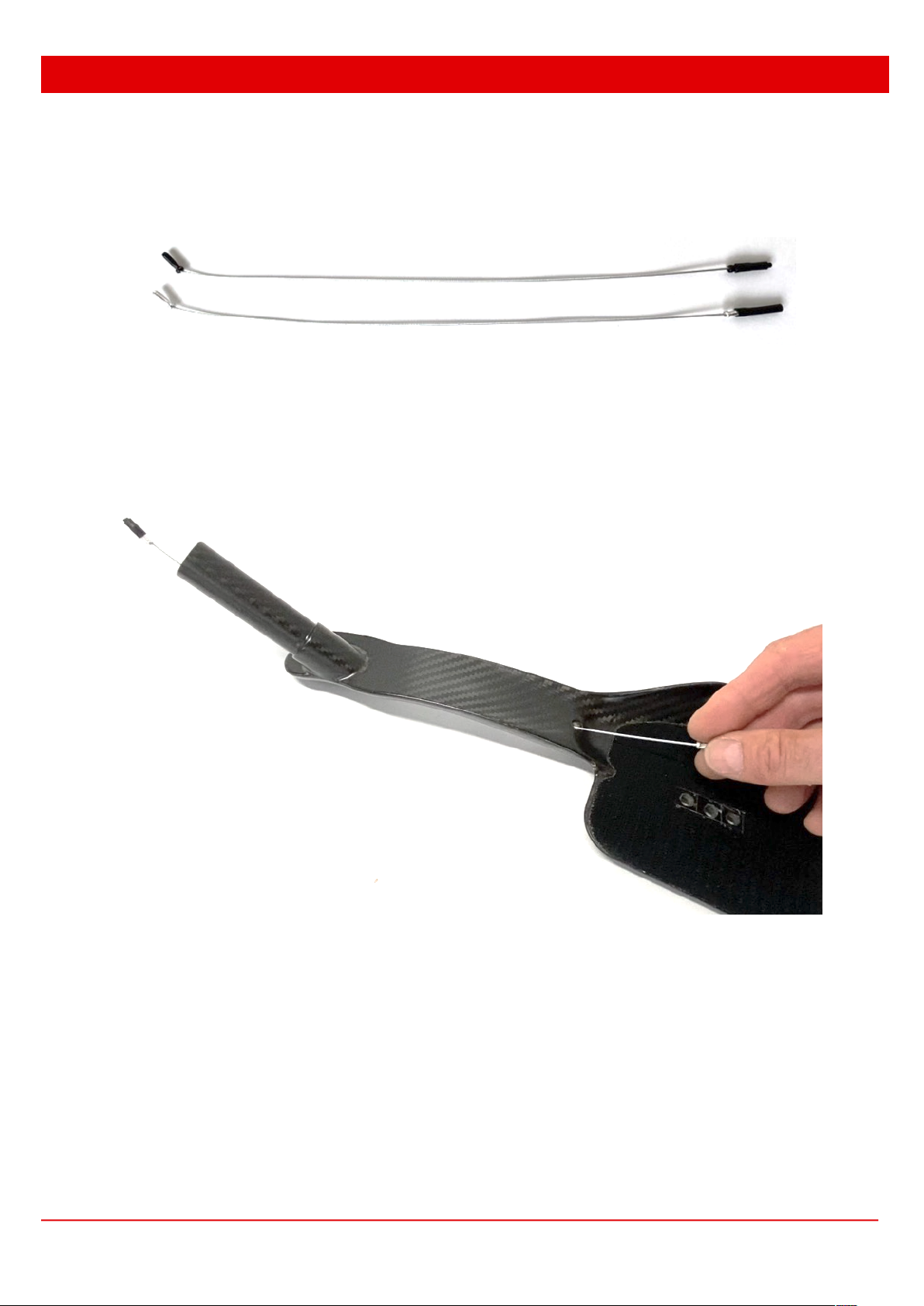
INSERTING ELECTRONIC SHIFTER CABLES AND INSTALLING THE SHIFTERS
The shifter cable must be drawn through the internal bar cavity and out the pre-drilled exit
hole. A shifter draw wire has been supplied for this purpose.
Remove the rubber grommet and insert the black end plug of the draw wire into the hole and
feed it through the bar until it exits out the end of the bar tube. If necessary, use the curve of
the cable to assist in guiding the draw wire into the bar tube.
Black
end
plug
SECTION C - CABLE INSTALLATION FOR ELECTRONIC SHIFTERS

10
www.fastTT.bike
FastTT Aero Bar Installation Guide – Tri Bar
Plug the shifter cable into the black tip of the draw wire as shown below and carefully pull it
through the bar so that it appears at the rear exit hole. Pull it clear of the rear exit hole and
unplug the shifter cable from the draw wire.
• Di2 - firmly insert the black tip of the draw wire into the Di2 plug connector
• SRAM – firmly insert the silver SRAM cable plug into the black tip of the draw wire
For older Di2 shifters where the cable inserts from outside the bar tube, the draw wire is fed
from the opposite direction i.e. feed it into the hole at the base of the bar end tube and out
the rear hole.
Di2
SRAM
SECTION C - CABLE INSTALLATION FOR ELECTRONIC SHIFTERS

11
www.fastTT.bike
FastTT Aero Bar Installation Guide – Tri Bar
Insert the shifters and tighten according to the manufacturer’s instructions.
To route the shifter wire, insert it down an unused open hole or over the back edge of the bar,
and route it to the junction box. Fix the wire into the channel in the adjustable angled riser, or
FastTT spacers.
SECTION C - CABLE INSTALLATION FOR ELECTRONIC SHIFTERS
SECTION D – MOUNTING THE BARS

12
www.fastTT.bike
FastTT Aero Bar Installation Guide – Tri Bar
Fit the rubber grommet around the shifter wire and insert it into the shifter exit hole. Re-install
the foam elbow pads.
SECTION C - CABLE INSTALLATION FOR ELECTRONIC SHIFTERS

13
www.fastTT.bike
FastTT Aero Bar Installation Guide – Tri Bar
INSTALLING MANUAL SHIFTER CABLES AND SHIFTERS
Insert the shifter cable outer into the hole at the base of the front bar end and feed it through
the pre-drilled exit slot below the extension section.
Route the shifter cable to the derailleur according to the most efficient route. Try to keep the
cable as close to the frame as possible for maximum aero efficiency.
Insert the shifters and tighten according to the manufacturer’s instructions.
SECTION D – MOUNTING THE BARS
SECTION D - CABLE INSTALLATION FOR MANUAL SHIFTERS
Insert cable outer
into pre-drilled
hole
Cable exit hole

14
www.fastTT.bike
FastTT Aero Bar Installation Guide – Tri Bar
The computer mount on your bars is compatible with Garmin and Wahoo. Set the correct
orientation of the insert for Garmin or Wahoo and lightly tighten the fastening screws (see
visual below). Place your computer onto the mount, loosen the screws, adjust the computer
position to suit, tighten the screws (but don’t overtighten).
IMPORTANT: FastTT Tri bars will NOT fit Garmin 1000 Series or any oversize touring
computers. Max computer size and weight is 82mm L x 50mm W, 123g (e.g. Garmin 830).
Attempting to fit a larger computer may damage the computer bracket and
void the warranty.
SECTION E - ADJUSTING THE COMPUTER
IMPORTANT SERVICE NOTE!
After a few rides we recommend that you check and retighten the mounting bolts on your FastTT
Aero Bars. The bolts can become slightly loose after initial riding due to natural bedding in of the
bolts into the carbon mounting base. This can potentially cause a small amount of lateral movement
in the bar. If this occurs, please retighten to a maximum of 6nm. If at any stage you notice lateral
movement of the bar you should retighten the bolts.

15
www.fastTT.bike
FastTT Aero Bar Installation Guide – Tri Bar
WARRANTY
FastTT Aero Bars are lightweight carbon competition units. In the event of a fall or harsh
impact, please check the bars carefully for any visible damage. Whilst carbon fibre is
exceptionally strong, it does not tolerate impacts, and damage that is invisible to the naked
eye can occur. This could result in unexpected breakage and injury, even death. If in doubt,
please have your bars checked by a reputable carbon repair company.
The manufacturer (Bold Horizon Ltd t/a FastTT) assumes no responsibility or liability for any
injury, loss or damage caused as a result of using this product under any conditions. FastTT
Aero Bars are supplied with a 24-month manufacturers defect warranty. Any damage caused
by misuse, incorrect installation, modification, accident, or any other cause is not covered by
the manufacturer’s warranty.
In the event of a warranty claim the manufacturer reserves the right to replace, repair or credit
the full purchase price excluding shipping (where applicable). In the event of a replacement or
repair, the cost of returning the unit to the manufacturer will be paid by the customer. The
manufacturer will pay for shipping of the repaired or replacement unit to the customer.
SPECIFICATIONS AND INSTALLATION INSTRUCTIONS
Specifications and installation instructions are subject to change without notice. To the best of
our knowledge, all information is correct at time of publishing The manufacturer is not
responsible for changes to UCI, World Triathlon and Ironman® technical regulations. It is the
customer’s responsibility to remain informed of any rule changes and to make the necessary
changes to bike setup for compliance.
CRASH REPLACEMENT COMMITMENT
If you're unfortunate enough to have a crash and damage your FastTT aero bars where they're
no longer safe to use, send them back to us and we'll replace them with a brand new set at
50% off the current retail price, including free shipping. It's tough enough crashing, but at least
we can help a little to ease your pain.
Contact us via email: [email protected] or message us on Instagram: @fastTT.bike
Copyright © 2022 FastTT - The Sports Product Division of Bold Horizon Ltd
SECTION F – WARRANTY AND DISCLAIMER
Other manuals for Carbon Aero Bar
2
This manual suits for next models
1
Table of contents
Other FastTt Bicycle Accessories manuals


