Fastway e2 92-00-0450 User manual

1
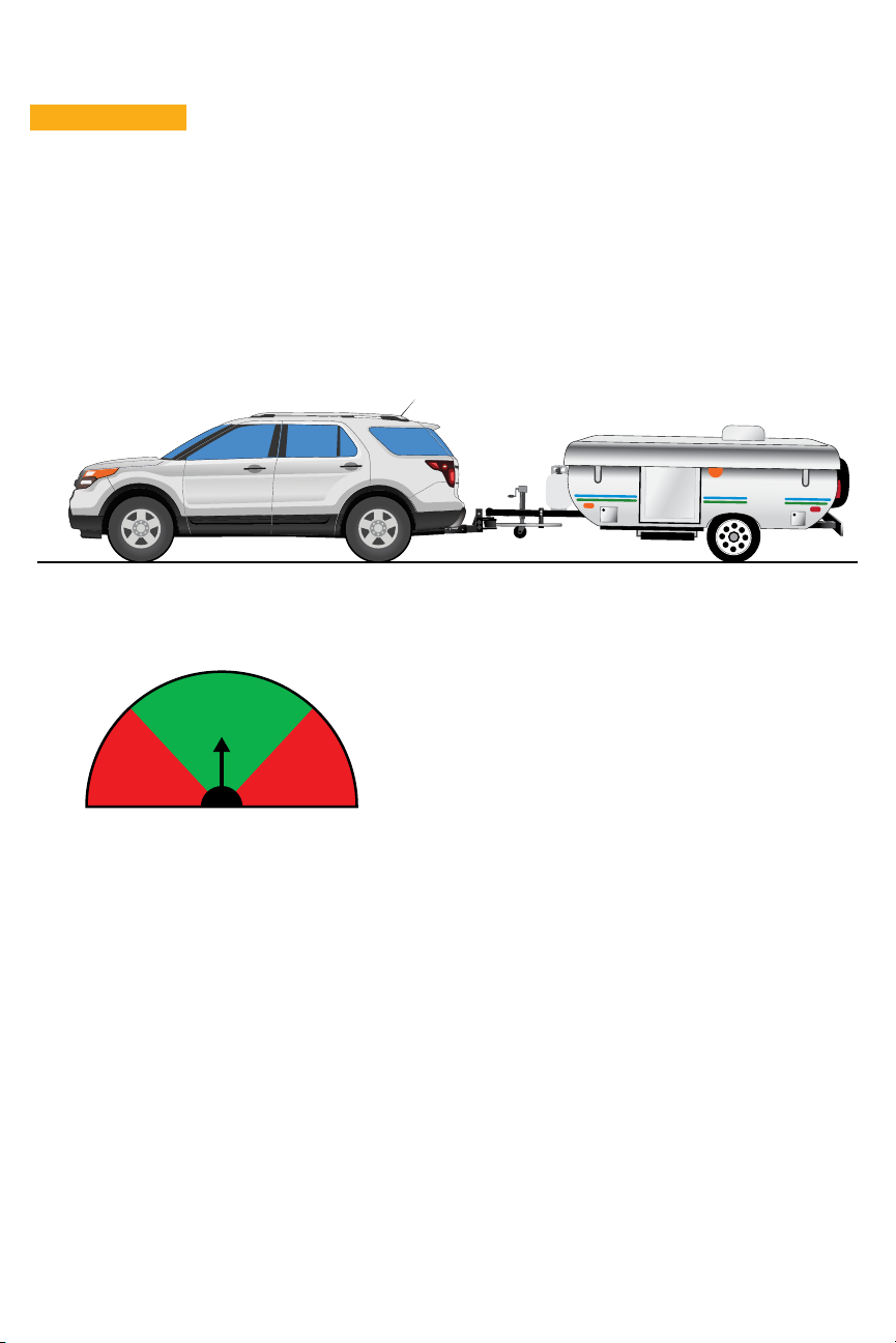
owner’s manual
fastwaytrailer.com A Product of Progress Mfg. Inc.
Fastway e2 Hitch - Faster, Easier.
™
Model Max Tongue Wt (lb) Max Trailer Wt (lb)
92-00-0450 450 4,500
Hitch ball not included.
Read the entire manual before starting installation.
Dealer: Please give this manual to the end user after
hitch installation.
Your model # can be found on the stickers on either
spring bar.
2
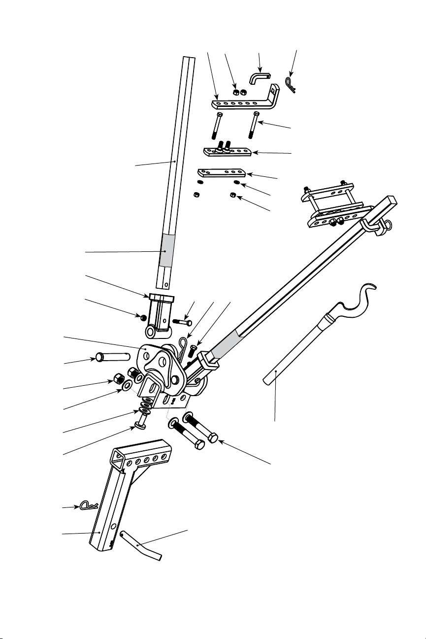
Parts Breakdown
25
24 23
22
21
20 19
17
18
16
15
14
13
12
1110
8
9
7
6
5
4
3
2
2
2
1

3
U.S. Pat. No. 8,833,789 and 8,628,107. Other patents pending.
Item # Part Number Part Description Qty.
192-02-4116 Adjustable shank 1
292-04-9705 Cotter pin / R-clip 5
392-04-9650 Spacer rivet 1
492-04-9655 ½” spacer washer 3
592-04-9726 5/8” flat washer 4
692-04-9736 M16-2 nylock nut (class 8) zinc 2
792-04-9743 ¾” X 4” clevis pin 2
892-02-0426 Hitch head 1
992-04-9766 M8-1.25 nylock nut (class 8) zinc 2
10 92-02-0456 4.5K trunnion knuckle 2
11 -- Spring bar sticker 2
12 92-02-0496 4,500 lb spring bar (single) 2
13 92-02-5140 L-bracket 2
Item # Part Number Part Description Qty.
14 92-03-9486 7/16”-14 nylock nut (grade 5) 4
15 92-03-9460 L- pin 2
16 92-03-9470 3/8”-16 X 3-½” hex bolt (grade 5) 4
17 92-02-5354 Outside link plate 2
18 92-02-5240 Inside link plate 2
19 92-03-9490 3/8” split washer 4
20 92-03-9475 3/8”-16 nut (grade 5) 4
21† 92-04-9756 M8-1.25 x 55 HCS (Class 8.8) zinc 2
22 92-03-9746 3/8”-24 X 1” HCS (grade 5) zinc 1
23 92-02-6040 Snap-up lever 1
24 92-04-9786 M16-2 X 100 HCS (class 8.8) zinc 2
25 92-04-9625 Hitch pin 1

4
Contents
Safety Information 5
Installation 6
Step 1 – Ready the Tow Vehicle and Trailer 6
Step 2 – Install the Hitch Ball 6
Step 3 – Attach the Hitch Head to the Shank 7
Step 4 – Assemble the Sway Brackets 8
Step 5 – Install Spring Arms 9
Step 6 – Set Up Weight Distribution 10
Step 7 – Adjust Weight Distribution 12
Step 8 – Adjust Trailer Pitch 13
Step 9 – Final Tightening 13
Maintenance and Care 13
How to Hitch 14
How to Unhitch 15
Appendix – Using a Weight Distribution Hitch
with Auto-Leveling Suspensions 15
Customer Support 16
Warranty 16
Find us Online 16

5
Safety Information
ÁWARNING
• Failure to follow all safety warnings may result in severe injury or death.
• Always adjust equipment and driving habits to match towing conditions. The driver is
responsible for their own safety and the safety of their passengers.
• Always check all hardware before each trip. Never tow your trailer until all bolts and nuts
have been checked for wear and fatigue, are properly tightened, and all pins and clips are
secured.
• Always load the trailer correctly. Follow the trailer and tow vehicle manufacturers’
recommendations for placement and quantity of cargo.
• Always use a hitch ball with a rating that equals or exceeds the trailer Gross Vehicle Weight
(GVW). Always use a hitch ball size that correctly matches your trailer coupler size and make
sure it is coupled securely before towing.
• Never cut, weld, grind, bend, or modify hitch components in any way.
• Never exceed the specified weight ratings for the trailer, tow vehicle, hitch, hitch ball, or any
other towing equipment.
• Never tow with your hitch adjusted incorrectly.
• Never tow with your hitch engaged on rough roads, through profound ditches and dips, or
while launching a boat. Excessive strain on the spring arms and hitch head may cause hitch
fatigue or failure.
• Never transfer your hitch to a different tow vehicle or trailer without adjusting the hitch for
proper setup and weight distribution.
• No hitch setup guarantees that trailer sway will be altogether avoided.
• Read, understand, and follow all safety warnings, setup, use, and maintenance instructions of
the trailer, tow vehicle, and hitch equipment before installing the hitch or towing your trailer.
• Replace worn, faded, or unreadable warning stickers on the spring arms and arm sockets.
• The operator is responsible for making necessary adjustments to the hitch to optimize weight
distribution and sway control. Verify that the hitch is adjusted correctly after loading the
trailer and tow vehicle for each trip. The weight distribution setup and towing performance
should be evaluated by the operator and adjusted when necessary.
• Towing with a tongue weight that is not within 10 — 15% of your Gross Trailer Weight (GTW)
increases the likelihood for loss of vehicle control and/or equipment failure.
ÁCAUTION
• Always secure the tow vehicle and trailer with the parking brake and wheel chocks before
setting up or adjusting the hitch.
• Disengage weight distribution before towing or backing the trailer where there is a significant
transition in grade. For example, backing from a level street onto a driveway with a steep
uphill slope. Failure to disengage the hitch will put excessive strain on the trailer and receiver
hitch.
• Never loosen or remove any part of the hitch while the hitch is under load. Use the tongue jack
to take the tension off the spring arms before removing the L-pins.

6
Installation
Step 1 – Ready the Tow Vehicle and Trailer
Park the trailer and tow vehicle on flat, level ground and in line with each other. Chock the
trailer.
For accurate installation the tow vehicle and trailer should be loaded just as they will be while
traveling. This includes propane, water, ATVs, generators, and/or any other cargo that the tow
vehicle or trailer will carry.
Check and inflate all tires to their proper pressure.
Tow vehicle auto-level systems should be disabled or turned off temporarily. Auto leveling and
air suspension systems will decrease the amount of weight distribution provided by the hitch after
setup. See Appendix for more information.
Step 2 – Install the Hitch Ball
Tools needed:
• Torque wrench capable of 250 ft-lbs
• 1 1/2” socket
ÁWARNING
Never exceed the specied weight ratings for the trailer, tow vehicle, hitch,
hitch ball, or any other towing equipment.
Select a ball with a 1” — 1 ¼” diameter threaded shank. The weight rating must equal or exceed
your trailer’s gross vehicle weight (GVW). Torque the nut to the manufacturer’s specifications.
The hitch ball should be tightened to 250 ft-lb, or to the recommended torque specification of the
hitch ball manufacturer. Contact an authorized e2 hitch dealership for service appointments and
cost if you need help installing the hitch ball.

7
Step 3 – Attach the Hitch Head to the Shank
Tools Needed:
• Torque wrench capable of 130 ft-lb
• 15/16” Socket with ratchet (Shank bolts)
• 9/16” Socket or box-end wrench (Angle set bolt)
Level the Trailer (Parallel to the Ground)
Measure to the ground at the front and back of the trailer frame and
adjust the trailer to be parallel to the ground. Both front and back
measurements should be the same.
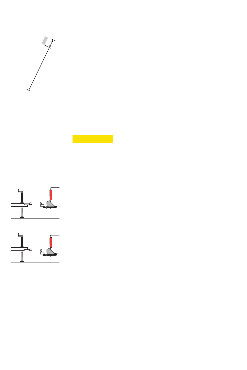
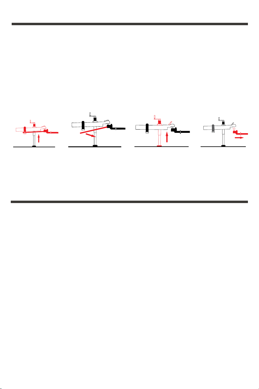
Attach Head to Shank
1. Insert the adjustable shank into the receiver on the tow vehicle and
secure it with the hitch pin.
2. Insert the spacer rivet with washers into the back of the hitch head.
Start with 3 spacer washers for most setups. (Figure 1)
3. Slide the hitch head onto the shank with the top of the hitch ball
between 0 — 1” above the top of the trailer coupler. (Figure 2) In some
cases you may need to turn the shank upward or use a bigger rise/drop
Fastway shank to place the hitch ball at the correct height. (Figure 3)
4. Use the 16mm bolts, 5/8” flat washers, and nuts to secure the head to
the shank at the correct height. Hand tighten the nuts. (Figure 4)
5. Use a wrench to tighten the angle set bolt until the spacer rivet is
firmly against the shank. (Figure 5)
Reduced Turning Radius or Clearance
Extended bumper guards, truck campers or rear mounted spare tires
can limit your turning radius. In a tight turn this can lead to a collision
between your tow vehicle and trailer. Certain trailer configurations and
safety chain orientation can reduce the amount of clearance needed for
safe towing. Check these items first to ensure proper clearance.
0 - 1”
Figure 1
Figure 2
Figure 3
Figure 4 Figure 5
8
Step 4 – Assemble the Sway Brackets
Tools Needed:
• 9/16” Box-end or socket wrench (Link plates)
• 5/8” Box-end or socket wrench (L-brackets)
• Measuring tape
Sway Bracket Location
1. Install the bracket assemblies between 25” — 30” from the center
of the coupler. (Figure 6) This range should allow you to avoid
most obstructions on the trailer tongue like battery supports or
propane tanks.
2. Measure along the frame from the center of the coupler to the
center of the brackets.
3. Both brackets should be the same distance from the coupler.
4. If necessary, relocate items on the frame to allow installation of
the brackets within this range.
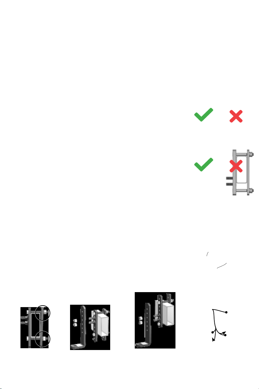
ÁCAUTION
Do not use an impact wrench to tighten the link plate
or L-bracket bolts.
Assemble the Link Plates
Partially assemble the brackets:
1. Insert one 3/8” x 3-1/2” bolt through the outside link plate going
the opposite direction as the L-bracket mounting bolts.
2. That same bolt should pass through the top hole of the inside link
plate.
3. The bolt heads should fit completely into the recessed slots.
4. Slide a 3/8” split washer onto the frame bolts and thread on
a 3/8” nut a few turns. Do not use lock nuts on these bolts.
(Figure 7)
Identify your coupler style and follow the correct step for your style.
(Figure 8)
Typical Installation - Top-mounted Couplers
1. Slide the link plate assembly down over the frame hanging from
the top bolt with the mounting bolts facing out.
2. Insert the second 3/8” x 3-1/2” bolt through the open hole closest
to the bottom of the trailer frame. (Figure 9)
3. Insert the bolt head into the slot and add a 3/8” lock washer and
thread a 3/8” nut onto the end of the bolt.
Inverted or Upside-Down Installation – Bottom-mounted
Couplers, V-nose Trailers
Install the assembly upside-down if you have a trailer with a bottom-
mount coupler, V-shaped nose, or any other obstacle that prevents
them from being installed right-side up.
Figure 6
Figure 7
Figure 8
Figure 9
25” min / 30” max
Top-Mounted
Inverted
9
c d
a b
Grease
here
Figure 10
Figure 11
Figure 12
Figure 13 Figure 14 - Initial
position for top-
mounted coupler.
Figure 15 - Setup for
bottom-mounted
coupler.
Figure 16
1. Slide the assembly up around the frame until the bolt hits the bottom
of the trailer frame with the mounting bolts facing out.
2. Insert the second 3/8” x 3-1/2” bolt through the open hole closest to
the top of the trailer frame. (Figure 10)
3. Insert the bolt head into the slot and add a 3/8” lock washer and
thread a 3/8” nut onto the end of the bolt.
No Gaps
For either typical or upside-down installation there should not be a gap
between the trailer frame and the link plate bolts either above or below
the trailer frame. Move electrical or propane lines if necessary. (Figures
11a-11d)
Pinch the link plates flat against the sides of the trailer frame, and hand
tighten both nuts. (Figure 12, 13)
When the nuts have been tightened by hand and both link plates are held
flat against the frame, use a torque wrench to tighten all the link plate
bolts to 27 ft-lb.
L-bracket Installation
Place the L-bracket onto the outside link plate with the bolts in the two
middle holes. Thread on the nylock nuts and hand tighten them until the
L-brackets are held firmly in place. (Figures 14, 15)
Step 5 – Install Spring Arms
The e2 4.5k trunnion arms are NOT side specific.
Insert the spring arm into hitch head and line the knuckle holes with the
corresponding holes in the head. (Figure 16)
Place the ¾” retaining pin through the holes and secure with the cotter
pin.
Lubricate the pin and knuckles frequently.

10
Step 6 – Set Up Weight Distribution
Tools Needed:
• Measuring tape
• Pencil
Good weight distribution is a critical component of the e2 trunnion hitch setup. To ensure proper
weight distribution, measure the front fender of the tow vehicle three times in different vehicle
configurations.
1. Measure without the trailer coupled.
2. Measure with the trailer coupled with the spring arms unattached.
3. Measure with the trailer coupled and the spring arms attached.
For best accuracy, measure both the driver and passenger fenders and use the average of these
two measurements for the calculations. (Figure 17)
Weight Distribution Calculation Table
Weight Distribution Setup Table Front Fender Height Example
AUncoupled from trailer 30”
B Trailer coupled and on hitch ball without
weight distribution
31”
C Fully hitched up with weight distribution
engaged
30 ¼”
Calculated weight distribution: 100*(B-C)/
(B-A)
75%
Target Between 50-100%
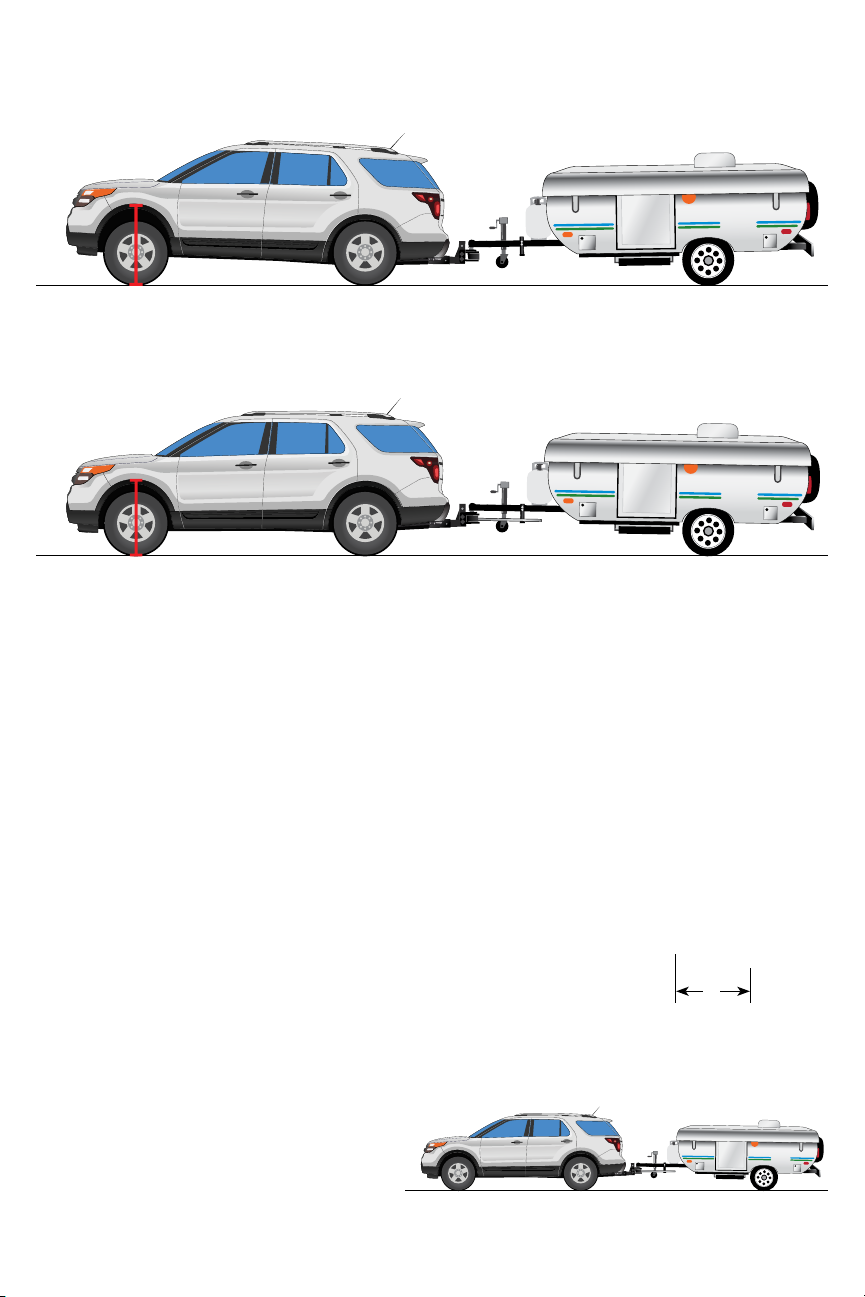
A – Measure from the ground to the bottom of the tow vehicle driver side front wheel well and
record the distance on line A of the weight distribution calculation table. (Figure 18)
Measure from the ground to
fender through the center-
line of the axle.
Figure 17
Figure 18
11
Retract the jack until the full weight of the trailer tongue is on the hitch.
Verify that there is a minimum of 3” from the end of the spring arms to
the center of the L-bracket. (Figure 23) If there is less than 3” the brackets
must be moved forward. Disconnect the hitch and move the brackets
forward.
With the trailer coupled and weight distribution engaged (spring arms in
place and jack retracted), measure from the ground to the bottom of the
tow vehicle driver side front wheel well. Record this distance on line C of
the weight distribution calculation table. (Figure 24)
To calculate the weight distribution
percentage- find the difference between
B and C, then divide by the difference
between B and A, then multiply the result
by 100.
B – Lower the trailer onto the hitch ball and lock the coupler. The full weight of the tongue
should be resting on the hitch. Measure from the ground to the bottom of the tow vehicle driver
side front wheel well. Record this distance on line B of the weight distribution calculation table.
(Figure 19)
C – With the trailer still coupled, use the tongue jack to lift both vehicles until the spring arms
can swing onto the L-brackets. (Figure 20) If needed, use the Snap-up lever to lift the spring
arms onto the L-brackets. (Figure 21) Insert the L-pins and secure them in place. (Figure 22)
3”
Figure 19
Figure 20
Figure 21 Figure 22
Figure 23
Figure 24
12
Step 7 – Adjust Weight Distribution
ÁWARNING
Weight distribution is one of the many things that reduces sway. The
operator is responsible for making other necessary adjustments to all
contributing factors to minimize sway.
Good Weight Distribution Range
Good weight distribution adjustment is achieved if your calculated weight distribution
falls between 50 — 100%. Every tow vehicle and trailer combination will be different.
Refer to your tow vehicle owner’s manual for exact ratings. Do not exceed 100% weight
distribution. (Figure 25)
Under or Over Distributed
Under Distributed means less than 50% weight
distribution after installation (or less than the
minimum directed by the tow vehicle owner’s
manual), measured at the front axle of the tow
vehicle. In this case, there is too much weight
on the rear axle and not enough weight on the
front axle. This can cause a loss of steering and
braking control with reduced resistance to trailer
sway. To correct under distribution, add more spacer washers to the hitch head or raise the
L-brackets.
Over Distributed means more than 100% weight distribution return (or more than the maximum
directed by the tow vehicle owner’s manual), measured at the front axle of the tow vehicle. Over-
distribution can remove too much weight from the tow vehicle’s rear axle. This can cause a loss
of traction and control causing jack-knifing, especially in slick road conditions. To correct over
distribution, remove spacer washers from the hitch head or lower the L-brackets.
Make Weight Distribution Adjustments
1. Use the tongue jack to raise both vehicle and trailer.
2. Unload and remove the spring arms.
3. Unhitch the trailer, then change the number of spacer washers and/or the position of the
L-brackets.
4. Hitch the trailer again and engage the spring arms.
5. Retract the jack so the hitch is carrying the trailer weight.
6. Measure the front fender and enter this new distance on line C of the weight distribution
calculation table.
Good Adjustment
150%0%
50% 100%
Over Distributed
Under Distributed
Figure 25
Figure 26

13
7. Calculate the new weight distribution amount using the previous distances for lines A and B,
and the new distance for line C.
8. Repeat until the measurements show that the hitch is distributing weight correctly.
Step 8 – Adjust Trailer Pitch
After achieving good weight distribution, you may need to adjust the pitch or angle of the trailer
to make it level (parallel to the ground) while towing. Measure from the ground to the front and
rear of the trailer frame.
If the difference between the front and rear measurements is more than 1 ¼” adjust the hitch ball
height. Move the hitch head up or down on the shank as needed. If the difference is less than 1
¼” complete Step 9 and tow a short distance with this setup to see how it handles before making
any adjustments.
After making any adjustments to the ball height, fully hitch and engage the spring arms and
remeasure the front wheel well, for line C of the weight distribution table. Update line C and
calculate the new weight distribution percentage using the previous measurements for lines A
and B.
Make more adjustments if needed until both the weight distribution is correct, and the trailer is
level (parallel to the ground).
Step 9 – Final Tightening
After the weight distribution and trailer pitch are correct, all the bolts on the hitch must be
tightened completely to their recommended torque specifications.
Torque Specifications ft-lb
(2) 16mm Shank Bolts 130
(4) 3/8”x 3-1/2” Link plate bolts 27
(4) 3/8” L-bracket nuts 45
Angle set bolt Set against shank + 1/2 turn
You are now ready to tow the trailer. Remove the wheel chocks and connect the breakaway cable,
safety chains, and electrical cable. Adjust your brake controller correctly. Retract the jack completely.
Maintenance and Care
Friction surfaces of the head and sockets should be
cleaned and lubricated with a good quality multi-purpose
lubricant or bearing grease before each trip. This includes
the hitch ball. Lubricate the surfaces where the arm
knuckles rub. (Figure 27) Do not lubricate the spring
arms or L-brackets. We recommend Equal-i-zer high
performance lubricant. (part # 91-00-4250)
Grease
here
Figure 27

14
Check for damage or abnormal wear at the beginning of each trip and replace damaged and
worn parts as necessary. Clean dirt and debris from all the friction surfaces regularly.
All nuts and bolts should be checked before each trip and tightened if necessary.
Store your hitch out of the weather when not in use. Use a good quality spray paint to touch up
the finish and help prevent rust. Do not paint over the warning stickers. If the warning stickers
become unreadable, contact Fastway for a free replacement.
A properly maintained and clean hitch will perform better and reduce wear and towing noise.
How to Hitch
1. With the Fastway hitch head installed, position the hitch ball directly under the trailer
coupler. (Figure 28)
2. Lower the trailer coupler until it is resting on the hitch ball. If the trailer coupler won’t sit
properly, adjust the position of your tow vehicle. (Figure 29)
3. Lock the coupler and insert the safety pin into the coupler latch.
4. Insert the spring arms into the hitch head and ensure that the retaining pin is secure.
(Figure 30)
5. Raise the trailer jack until you can slide the spring arms onto the L-brackets; if needed, use
the Snap-up lever. (Figure 31)
6. Insert the Snap L-pins.
7. With both arms secured, lower the jack, then retract it completely. (Figure 32)
8. Attach the safety chains and breakaway cable.
9. Insert the 7-pin plug. Make sure the plug is clean and free of debris.
10. Remove your wheel chocks.
11. You are ready to go!
Figure 28 Figure 29 Figure 30
Figure 31 Figure 32
15
How to Unhitch
1. Properly chock your trailer.
2. Remove the 7-pin plug.
3. Remove the breakaway cable and safety chains.
4. Extend your trailer jack to lift the weight off the spring arms. (Figure 33)
5. With the tension off the spring arms, remove the Snap L-pins and slide the spring arms off
the L-bracket. (Figure 34)
6. Remove the spring arms from the hitch head.
7. Remove the safety pin and unlock the coupler.
8. Raise the trailer coupler above the hitch ball. (Figure 35)
9. Pull your tow vehicle away slowly, lock your trailer coupler and you are done. (Figure 36)
Appendix – Using a Weight Distribution
Hitch with Auto-Leveling Suspensions
Always refer to and follow your tow vehicle owner’s manual or air bag instructions for their
requirements for use while towing. Auto Leveling will greatly affect your towing situation.
Step 1 - Ready the Tow Vehicle and Trailer
Turn off or disable air bag suspension or auto-leveling systems for the hitch setup process. Allow
the suspension to adjust to normal position before turning it off. To turn the auto level off, the
system may have an off switch, a jack mode setting, or you may need to turn off the vehicle.
Steps 6 and 7 – Set Up and Adjust Weight Distribution
4 Corner Auto-Leveling Suspension:
4-corner auto leveling systems will decrease the weight distribution amount by 20 — 25%. If it is
possible to disable the auto leveling so that it remains off while driving, do so. If not, then set up
the hitch so that 75 — 100% weight distribution is achieved. This will help compensate for the
loss from auto leveling.
Rear Auto-Leveling Suspension:
When using rear auto-leveling suspension systems follow the instructions to Step 6 - line C. Allow
the vehicle to auto level the rear before taking measurement C. On hydraulic or pneumatic
systems this is done by turning the vehicle on and letting the engine idle while it levels. If your
vehicle is equipped with a system that requires the tow vehicle to be driven, mark where it is
parked so that you can return to the same spot after driving to take measurement C.
Figure 33 Figure 34 Figure 35 Figure 36

16
Step 8 - Trailer Pitch Adjustment
After achieving good weight distribution with auto level engaged, the trailer pitch may need to
be adjusted. Measure the trailer as described in Step 8 and make any required adjustments to the
hitch setup.
Hitching Up and Unhitching
Before hitching or unhitching, turn off the auto-level system by turning off the vehicle or, if
equipped, placing the system in jack mode.
Customer Support
If you need customer support, or replacement parts and accessories, please contact our customer
support team. Please call us at 877.523.9103, send us an email at support@fastwaytrailer.com or
use the chat feature on fastwaytrailer.com. Our team is available Monday through Friday, 8AM
to 5PM (Mountain Time).
Warranty
Limited 10 Year Warranty: Progress Mfg. Inc. warrants the e2™ hitch against latent defects
in materials and workmanship under normal use and service, ordinary wear and tear is
excepted, to the original owner for a period of 10 years from the first date of purchase at
retail up to the value of its original purchase price. If this product is latently defective it will
be replaced or repaired when a proper return authorization is obtained and the product
is returned with transportation charges prepaid to Progress Mfg. Inc. Progress Mfg. Inc.
shall not be required to replace or repair any products damaged as a result of improper
installation, alteration, unreasonable use, or improper maintenance including, without
limitation, loading the product beyond the factory rated load capacity. This warranty
does not include labor charges, nor does it include transportation charges for returning
the product to the consumer. To the extent allowed by law, Progress Mfg. Inc. shall not be
liable for any incidental, consequential, or any other damages including, without limitation,
breach of any implied warranty, merchantability, or fitness for a particular purpose of any
e2 product. In no event shall Progress Mfg. Inc. be liable for any damages other than the
replacement or repair of the affected part. Authorization and warranty procedure may be
obtained by calling Progress Mfg. Inc. customer service at 877-523-9103.
Submit your warranty registration online at fastwaytrailer.com.
Find us Online
We would love to connect with you. Find us on these social media platforms.
youtube.com/fastwaytrailer
facebook.com/fastwaytrailer
twitter.com/fastwaytrailer
instagram.com/fastwaytrailer
Visit Fastway® Trailer Products at www.fastwaytrailer.com for faster and easier towing solutions.
Table of contents
Other Fastway Jack manuals


