Central Hydraulics 42820 User manual

Manual Operated
Floor Jack
OPERATING INSTRUCTIONS
Note: There may be some slight differences in the appearance of the various
®
3491 Mission Oaks Blvd., Camarillo, CA 93011
Copyright©2009 by Harbor Freight Tools®. All rights reserved. No portion of this manual or any artwork
contained herein may be reproduced in any shape or form without the express written consent of
Harbor Freight Tools. Diagrams within this manual may not be drawn proportionally. Due to continuing
improvements, actual product may differ slightly from the product described herein. Tools required for
assembly and service may not be included.

Page 2 Floor Jacks
Keep this manual for the safety warn-
ings and precautions, assembly, operat-
ing, inspection, maintenance and cleaning
procedures. Write the product’s serial
number in the back of the manual near the
assembly diagram (or month and year of
purchase if product has no number). Keep
this manual and the receipt in a safe and
dry place for future reference.
IMPORTANT SAFETY
INFORMATION
and all other information provid-
This is the safety alert
you to potential personal
safety messages that
DANGER indicates
WARNING
indicates a
NOTICE is used to
address practices
the safety alert
practices not related to
Safety Warnings
WARNING Read all safety
Failure to heed these markings
may result in personal injury and/or
property damage.
Study, understand, and follow all1.
instructions before operating this
device.
Do not exceed rated capacity.2.
Use only on hard, level surfaces.3.
Lifting device only. Immediately after4.
lifting, support the vehicle with appro-
priate means.
Do not move or dolly the vehicle5.
while on the jack.
Do not adjust safety valve.6.
Wear ANSI-approved safety goggles7.
and heavy-duty work gloves during
use.
Keep clear of load while lifting and8.
lowering.
Lower load slowly.9.
Do not use for aircraft purposes.10.
Apply parking brake and chock tires11.
before lifting vehicle.

Page 3 Floor Jacks
Lift vehicle only at manufacturer-rec-12.
ommended locations.
Inspect before every use; do not use13.
if parts loose or damaged.
Keep your work area clean and well14.
lit. Cluttered work areas invite acci-
dents.
Keep bystanders, children, and15.
visitors away while operating jack.
Distractions can cause you to lose
control.
Stay alert. Watch what you are do-16.
ing, and use common sense when
operating a jack. Do not use a jack
while tired or under the inuence of
drugs, alcohol, or medication. A mo-
ment of inattention while operating
jacks may result in serious personal
injury.
Store idle jacks out of reach of chil-17.
dren and other untrained persons.
Jacks are dangerous in the hands of
untrained users.
Jack service must be performed only18.
by qualied repair personnel. Service
or maintenance performed by unqual-
ied personnel could result in a risk of
injury.
When servicing a jack, use only iden-19.
tical replacement parts - refer to at-
tached, product-specic parts list and
diagram. Follow instructions in the
“Inspection, Maintenance, And Clean-
ing” section of this manual. Use of
unauthorized parts or failure to follow
maintenance instructions may create
a risk of injury and may void any ap-
plicable warranty.
Maintain labels and nameplates on20.
the Jack. These carry important
information. If unreadable or miss-
ing, contact Harbor Freight Tools for a
replacement.
Before use, read manufacturer’s21.
instruction manual for the vehicle (or
object) you will lift.
When lifting only one wheel, support22.
the load immediately with one jack
stand (not included) placed under the
side of the vehicle being lifted. Align
the saddle of the jack stand directly
under the vehicle’s seam or recom-
mended lifting point.
When lifting the entire front end23.
or rear end of a vehicle, support
the load immediately with two jack
stands. Align the saddles of the jack
stands directly under the vehicle’s
frame or recommended lifting points.
Also, adjust the jack stands to the
same height.
Do not work under the vehicle without24.
properly supporting the vehicle with
jack stands.
Avoid dangerous oncoming trafc. 25.
Use the Jack as far away from the
roadside as possible.
Industrial applications must follow26.
OSHA requirements.
Do not allow anyone in the vehicle27.
while using the Jack. Keep all by-
standers a safe distance away from
the vehicle.
Do not support both ends of the ve-28.
hicle at the same time.
Before lowering the Jack, remove all29.
tools and equipment from under the
vehicle.

Page 4 Floor Jacks
The warnings, precautions, and30.
instructions discussed in this manual
cannot cover all possible conditions
and situations that may occur. The
operator must understand that com-
mon sense and caution are factors,
which cannot be built into this prod-
uct, but must be supplied by the
operator.
UNPACKING
When unpacking, make sure that the
product is intact and undamaged. If any
parts are missing or broken, please call
Harbor Freight Tools at 1-800-444-3353 as
soon as possible.
OPERATION
Bleeding
IMPORTANT!
for proper hydraulic oil level in the
Jack for proper operation prior to
not
be necessary to bleed its hydraulic
Oil Fill Plug
1. Remove the cover plate (some mod-
els) and the Oil Filler Plug under-
neath. (See Photo above.)
Release Screw
Pivot Assembly
2. -
Insert the slot on the lower portion of
the Handle over the Release Screw
to operate it.
3.
built into the pivot point:
Rotate the handle to operate the Re-
lease Screw.
Turn the Release Screw4. counter-
clockwise to open valve.
Insert the Handle into the Pivot As-5.
sembly (See photo above.) Apply
pressure to the Saddle, and pump the
Handle quickly several times.
Check the Oil Fill Hole and, if nec-6.
essary, top off the Oil Fill Hole with
hydraulic oil.
Close the valve Release Screw by7.
turning handle clockwise and replace
the Oil Fill Plug and cover plate.
Test the Jack several times for proper8.
operation before attempting to lift a
load.
still does not

Page 5 Floor Jacks
1. WARNING! Park vehicle on a
Turn
off the vehicle’s engine. Place the
vehicle’s transmission in “PARK” (if
automatic) or in its lowest gear (if
manual). Set the vehicle’s emer-
gency brake. Then, block the wheels
that are not being lifted.
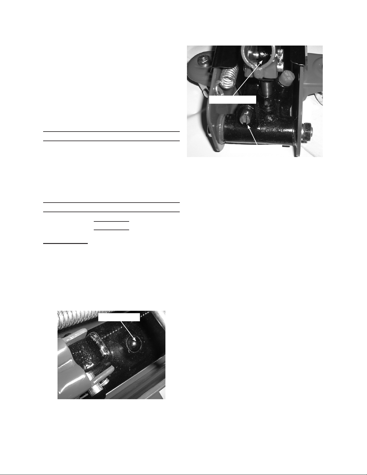
Turn the Release Screw2. counter-
clockwise to lower the Jack. Once
the Jack is fully lowered, turn the
Release Screw rmly clockwise to
close it.
Handle
Saddle
Carry Handle -
(Some models only)
Cover Plate -
(Some models only)
3. Carefully position the Saddle of the
Jack (see photo above) under the
vehicle manufacturer’s recommended
lifting point. If equipped, the Elevat-
ing Screw can be used to alter the
height of the jack’s saddle; it is ad-
justed by turning the saddle clock-
wise or counterclockwise. (See ve-
hicle manufacturer’s owner’s manual
for location of frame lifting point when
lifting only one wheel and frame lift-
ing points when lifting the entire front
or rear end of the vehicle.)
Pump the Handle until the top of the4.
Jack’s Saddle has nearly reached the
vehicle lifting point.
Note: The Jack should be positioned at
90° to the vehicle’s lifting point to
ensure the Jack’s Saddle and vehicle
lifting point are in alignment. If not,
reposition the Jack before lifting the
vehicle.
To lift the vehicle, pump the Handle of5.
the Jack. Use smooth, full strokes for
best results.
Once the vehicle is raised, slide a6.
jack stand of appropriate capacity
(not included) under the proper lifting
point referred to in the vehicle own-
er’s manual. If using two jack stands,
position them at the same point on
each side of the vehicle.
Center the vehicle’s lifting point(s) on7.
the saddle of the jack stand(s). Set
the jack stand(s) according to the
manufacturer’s instructions, making
sure that they lock securely into posi-
tion.
Note:
Slowly turn the Release Screw8. coun-
terclockwise to lower the vehicle onto
the saddle(s) of the jack stand(s).
Then, turn the valve Release Screw
rmly clockwise to close it.
While standing safely aside, gently9.
rock the vehicle to determine if it is
stable on the jack stand(s). If it is
not, raise the vehicle, and reposi-
tion the jack stand(s). WARNING!
When performing this procedure
be prepared and stand clear of the

Page 6 Floor Jacks
Remove all tools, parts, etc. from1.
under the vehicle.
Position the Saddle under the lifting2.
point. Turn the Release Screw rmly
clockwise, and pump the Handle to
raise the vehicle slightly above the
saddle(s) of the jack stands. Then,
lower the Saddle to its lowest position
and remove jack stand(s).
Slowly3. turn the Handle counterclock-
wise (never more than two full turns)
to lower the vehicle onto the ground.
Lower the Jack completely. Then,4.
store in a safe, dry location out of
reach of children.
explained in this manual
must be performed only by a
TO PREVENT
SERIOUS INJURY
Do not use damaged
If abnormal noise
problem corrected before
1. inspect the gen-
eral condition of the Jack. Check for
broken, cracked, or bent parts, loose
or missing parts, and any condition
that may affect the proper operation
of the product. If a problem occurs,
have the problem corrected before
further use.
2.
the Jack for proper operation prior
-
pears not
Bleeding instructions on
Change the hydraulic oil at least3.
once every three years:
With the Jack fully lowered, removea.
the Oil Filler Plug on the side of the
Housing.
Tip the Jack to allow the old hydrau-b.
lic oil to drain out of the Housing
completely, and dispose of the old
hydraulic oil in accordance with local
regulations.
With the Jack upright, completelyc.
ll the Housing with a high quality
hydraulic oil (not included) until the
oil just begins to run out of the Oil
Fill Hole.
Open the valve Release Screw andd.
pump the Handle to drive oil into
pump passanges as well to bleed
air from the system.
Reinstall the Oil Filler Plug.e.
Wipe dry with a clean cloth. Then,4.
store the Jack in a safe, dry location
out of reach of children and other
non-authorized people.

Page 7 Floor Jacks
Troubleshooting
TO PREVENT SERIOUS INJURY:
If the solutions presented in the Troubleshooting guide do not
solve the problem, have a qualied technician inspect and repair the jack before use.
:
Jack will not
lift at its weight
capacity
Saddle
lowers under
load
Pump stroke
feels spongy
Saddle will not
lift all the way
Handle moves
up when jack
is under load
Oil leaking
from ller plug
X X Check that Release Valve is closed fully.
Bleed air from the system.
X X X
Valves may be blocked and may not close
fully. To ush the valves:
Lower the Saddle and securely close the1.
Release Valve.
Manually lift the saddle several inches.2.
Open the release valve and force the3.
saddle down as quickly as possible.
XX X
Jack may be low on oil. Check the oil level
and rell if needed.
Jack may require bleeding - see instructions
on page 4.
XUnit may have too much hydraulic oil inside,
check uid level and adjust if needed.

Page 8 Floor Jacks
Harbor Freight Tools Co. makes every effort to assure that its products meet high
quality and durability standards, and warrants to the original purchaser that this prod-
uct is free from defects in materials and workmanship for the period of 90 days from
the date of purchase. This warranty does not apply to damage due directly or indirectly,
to misuse, abuse, negligence or accidents, repairs or alterations outside our facilities,
criminal activity, improper installation, normal wear and tear, or to lack of maintenance.
We shall in no event be liable for death, injuries to persons or property, or for incidental,
contingent, special or consequential damages arising from the use of our product. Some
states do not allow the exclusion or limitation of incidental or consequential damages, so
the above limitation of exclusion may not apply to you. THIS WARRANTY IS EXPRESS-
LY IN LIEU OF ALL OTHER WARRANTIES, EXPRESS OR IMPLIED, INCLUDING THE
WARRANTIES OF MERCHANTABILITY AND FITNESS.
To take advantage of this warranty, the product or part must be returned to us with
transportation charges prepaid. Proof of purchase date and an explanation of the com-
plaint must accompany the merchandise. If our inspection veries the defect, we will ei-
ther repair or replace the product at our election or we may elect to refund the purchase
price if we cannot readily and quickly provide you with a replacement. We will return re-
paired products at our expense, but if we determine there is no defect, or that the defect
resulted from causes not within the scope of our warranty, then you must bear the cost
of returning the product.
This warranty gives you specic legal rights and you may also have other rights
which vary from state to state.
3491 Mission Oaks Blvd. • PO Box 6009 • Camarillo, CA 93011 • (800) 444-3353
Note: If product has no serial number, record month and year of purchase instead.
Note: Some parts are listed and shown for illustration purposes only, and are not avail-
able individually as replacement parts.

SKU 42820 For technical questions, please call 1-800-444-3353.
SPECIFICATIONS
Weight Capacity 2-1/2 Tons (5,000 lb.)
Maximum Height 31-5/8"
Minimum Height 5-3/4"
ASSEMBLY
Install the Foot Pedal
The Pedal Link (41) is already assembled to the body of the jack.1.
To attach the Foot Pedal (38), pass the Bolt (42) through the Pedal Link and Foot2.
Pedal, and x in place using Washer (40) and Nut (39).
Note: The Foot Pedal (38) can be used to raise the Saddle.
Mount the Handle Assembly into Position.
First loosen the Nut (34) and Bolt (36) which are located just below the hole for the 3. handle in the Handle Socket (35).
Insert the Handle (72) into the Handle Socket. Be sure it is properly seated. Re-4. tighten the bolt and nut to secure the handle in place.
Note: Some parts are listed and shown for illustration purposes only and are not avail-
able individually as replacement parts.
PLEASE READ THE FOLLOWING CAREFULLY
THE MANUFACTURER AND/OR DISTRIBUTOR HAS PROVIDED THE PARTS DIAGRAM IN THIS MANUAL
AS A REFERENCE TOOL ONLY. NEITHER THE MANUFACTURER NOR DISTRIBUTOR MAKES ANY REPRESENTA-
TION OR WARRANTY OF ANY KIND TO THE BUYER THAT HE OR SHE IS QUALIFIED TO MAKE ANY REPAIRS TO
THE PRODUCT OR THAT HE OR SHE IS QUALIFIED TO REPLACE ANY PARTS OF THE PRODUCT. IN FACT, THE
MANUFACTURER AND/OR DISTRIBUTOR EXPRESSLY STATES THAT ALL REPAIRS AND PARTS REPLACEMENTS
SHOULD BE UNDERTAKEN BY CERTIFIED AND LICENSED TECHNICIANS AND NOT BY THE BUYER. THE BUYER
ASSUMES ALL RISK AND LIABILITY ARISING OUT OF HIS OR HER REPAIRS TO THE ORIGINAL PRODUCT OR
REPLACEMENT PARTS THERETO, OR ARISING OUT OF HIS OR HER INSTALLATION OF REPLACEMENT PARTS
THERETO.

SKU 42820 For technical questions, please call 1-800-444-3353.
Part Description Q’ty
1 Snap Ring 1
2 Washer 2
3O Ring 1
4 Pressure Piston 1
5 Pressure Piston Ring 1
6Sealing Washer 1
7O Ring 1
8O Ring Retainer 1
9Snap Ring 1
10 Cylinder 1
11 Housing 1
12 Oil Filler Plug 1
13 Cylinder Base 1
14 4mm Steel Ball 1
15 Spring Seat 1
16 Spring 1
17 Over Pressure Valve 1
18 Sealing Washer 1
19 Over Pressure Valve Plug Screw 1
20 6mm Steel Ball 3
21 O Ring 1
22 Release Valve Rod 1
23 Washer 1
24 Oil Valve 1
25 Washer 1
26 Pump Cylinder 1
27 Y Ring 1
28 O Ring 1
29 Dirt Proof Boot 1
30 Pump Plunger 1
31 Pin Rod 2
32 Washer 2
33 Torsion Spring (set of 2) 1
34 M10 Nut 1
35 Handle Socket 1
36 M10 x 50 Bolt 1
37 E-clip 10
38 Pedal 1
Part Description Q’ty
39 M10 Lock Nut 1
40 Spring Washer 1
41 Pedal Link 1
42 M10 x 55 Bolt 1
43 Pedal Rod 1
44 Rod 1
45 Rod 2
46 Rod 6
47 Spring Washer 12
48 Nut 12
49 Rod 1
50 Snap Ring 1
51 M12 x 1.25 Lock Nut 2
52 Rear Wheel 2
53 M18 x 1.5 Nut 2
54 18mm Spring Washer 2
55 Arm Shaft 1
56 Frame 2
57 M16 x 1.5 Nut 2
58 Washer 2
59 Shaft Sleeve 2
60 Front Wheel 2
61 Front Wheel Shaft 1
62 Saddle Base 1
63 Rod 1
64 Rod Link 2
65 Arm 1
66 Pin 1
67 Saddle 1
68 Rod 1
69 Spring 2
70 Cover 1
71 Handle Sleeve 2
72 Handle 1
73 Handle Knob 1
74 Pin 1
75 Convey Knob 1
PARTS LIST

SKU 42820 For technical questions, please call 1-800-444-3353.
ASSEMBLY DIAGRAM

18 mm
13.8mm
12 mm
9.13 mm
O ring
Central Hydraulics 2.5 ton floor jack 42820
3.44 mm
Table of contents
Other Central Hydraulics Jack manuals
Popular Jack manuals by other brands

Hamron
Hamron 601002 User instructions

Clarke
Clarke strong-arm CBJ30 Operation and maintenance instructions

Certa
Certa CTEXTJACKXA quick start guide

Cattini
Cattini YAK 315/L Operating and maintenance manual

Westward
Westward 3W929C Operating instructions and parts manual

Meganex
Meganex MEG103 instruction manual