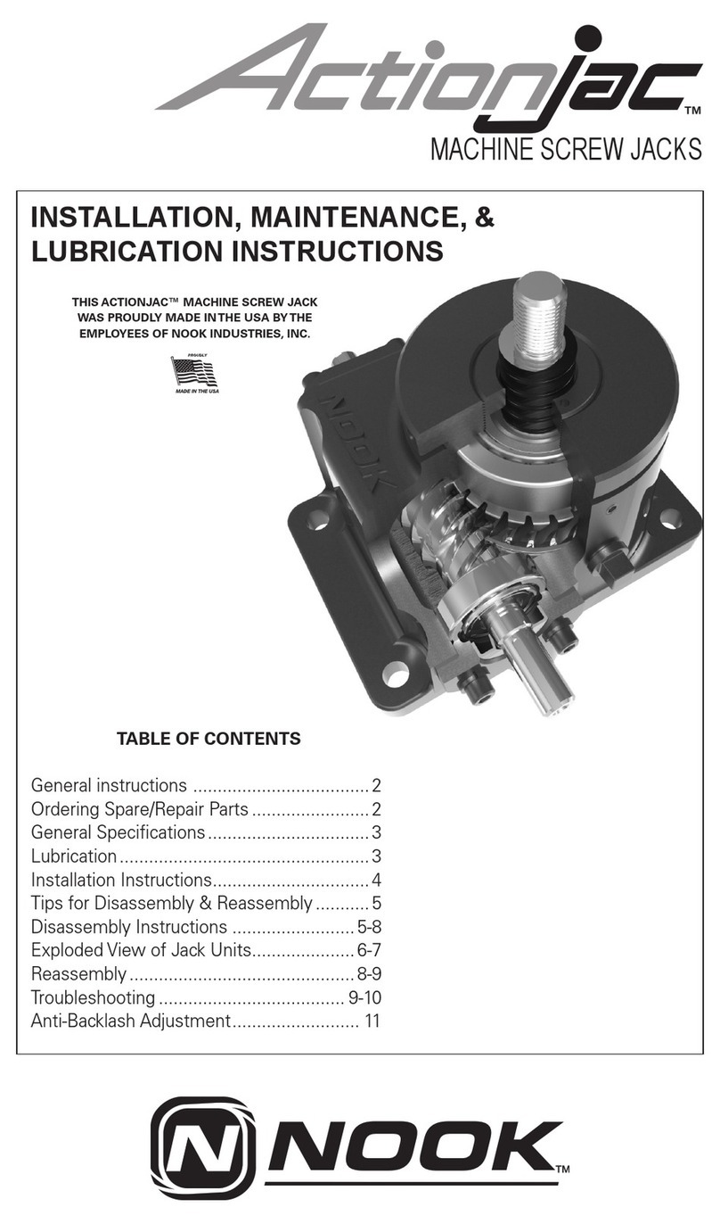
NOOK Actionjac Installation and operating instructions

BALL SCREW JACKS
INSTALLATION, MAINTENANCE, &
LUBRICATION INSTRUCTIONS
TABLE OF CONTENTS
General instructions .................................... 2
Ordering Spare/Repair Parts ........................ 2
General Specifications ................................. 3
Lubrication................................................... 3
Installation Instructions................................ 4
Tips for Disassembly & Reassembly ........... 5
Disassembly Instructions ....................... 5-10
Exploded View of Jack Units..................... 6-7
Reassembly ............................................... 10
Troubleshooting .....................................10-11
THIS ACTIONJAC™ BALL SCREW JACK
WAS PROUDLY MADE IN THE USA BYTHE
EMPLOYEES OF NOOK INDUSTRIES, INC.

2
CAUTION - The ActionJac™ Ball Screw
Jack may be self-lowering and therefore
the customer must provide some means
of holding the load.
The customer is responsible for providing
stops at either end of travel. Hard external
safety stops are recommended, since fail-
ure of brake or system components could
cause self lowering.
GENERAL INSTRUCTIONS
Your ActionJac™ Ball Screw Jack is a high
quality, sturdy unit designed to give many
hours of trouble-free service. However,
certain precautions and procedures must
be observed in handling, installing and ser-
vicing the unit in order to obtain optimum
performance.
1. Any apparent or suspected damage
sustained by equipment manufactured or
furnished by Nook Industries during trans-
port from the factory to the user should be
immediately reported to both Nook Indus-
tries and to the carrier.
2. Upon delivery all equipment furnished
should be carefully inventoried against
shipping papers to determine whether any
shortages exist in delivered material. Any
such shortages must immediately be re-
ported to Nook Industries and the carrier
if a timely claim is to be made.
3. The installation of most power transmis-
sion equipment does not normally require
the services of a factory engineer. These
services are not included in the selling
price of the equipment unless specifically
agreed upon in writing between the seller
and purchaser. In applications requiring a
more complex arrangement of compo-
nents, consideration should be given to
the use of a factory engineer for construc-
tion supervision or checkout of the instal-
lation. These services are available from
Nook Industries by contacting the Service
Department.
4. The Seller’s warranty applies insofar as
the unit is operated within the rating and
service conditions for which it was spe-
cifically sold. The purchaser must prevent
the existence of any destructive external
conditions which might typically include
vibratory loads due to critical speeds, se-
vere shock loading, mechanical or thermal
overloads, or side loads.
5. Adequate installation, maintenance and
safety instructions must be given by the
user to personnel directly responsible for
the installation and operation of the equip-
ment.
6. In the event of malfunction within the
warranty period, the manufacturer must
be informed promptly or, in any event,
within thirty days if it is intended that the
warranty is to cover the incident.
ORDERING SPARE/REPAIR PARTS
This booklet contains general instructions,
operating, maintenance and troubleshoot-
ing instructions for your ActionJac™ Worm
Gear Screw Jack. In the event spare or re-
pair parts are required, call your local rep-
resentative or contact Nook Industries at
(216) 271-7900 or 1 (800) 321-7800. Please
provide the following information when re-
questing spare/repair parts:
• Jack Size & Type Designation
(i.e., 2- BSJ)
• Serial Number & Year of Manufacture
(located on housing nameplate)
• Stroke Length
• Part description (see pages 6-7)
CAUTION - UNITS ARE NOT MEANT FOR
PERSONNEL SUPPORT. Refer all applica-
tions for potential personnel support to the
factory for approval.

3
GENERAL SPECIFICATIONS
The worm gear driven Ball Screw Jack
incorporates an alloy steel worm, which
drives a high tensile bronze worm gear,
accurately machined to the high standards
of Nook Industries for maximum load car-
rying capacity and uniformity of motion
transmission. All shafts are mounted on
heavy duty, anti-friction bearings to in-
crease operating efficiency of the drive
mechanism. Thrust bearings are provided
to support the rated thrust load of each
unit. Housings are made of high-strength
material, well proportioned to handle the
rated thrust and torque loads of each size
unit.
Ball Screw Jacks with translating screws
are fitted with a retainer for one direction
of travel only. Its purpose is to avoid inad-
vertently running the lifting screw out of
the jack and losing the balls from the ball
nut. THIS RETAINER IS NOT DESIGNED
TO FUNCTION AS A TRAVEL STOP. Care
must be taken if this stop collar is removed
as the ball screw can run out of the unit
and the recirculating balls will be lost from
the nut. Stops or collars are NOT provided
for units with traveling nuts unless specifi-
cally requested.
CAUTION - In the absence of internal or
external stops, it is possible to run the lift-
ing screw out of the unit. Your jack is NOT
equipped with internal stops unless spe-
cifically requested in your order.
A lifting screw cover is threaded into the
bottom of the unit on the upright model,
or in the top of the unit on the inverted
model, in order to keep the lifting screw
threads free of foreign material.
The lifting screw is made of 4150 heat
treated steel. The threads of the lifting
screw for all models should be well lubri-
cated and kept free of grit, dirt or other
abrasive contaminants.
Fabric type protective boots, or spiral steel
protectors, can be provided as an acces-
sory to protect the exposed portion of
the lifting screw. In the absence of posi-
tive stops, overtravel may crush protective
boots.
CAUTION - Standard units should not be
operated at input speeds over 1,800 RPM
without consulting the factory. Ball Screw
Jacks are designed for a maximum of
three hours of intermittent operation per
day. For values higher than three hours per
day, for any continuous operation, or for
repeated operation over any segment of
total travel, consult factory.
LUBRICATION
Gear Box Enclosure
The jack gearboxes are partially filled with
a lubricant at the factory unless otherwise
specified. Before operating any unit, verify
lubricant presence. All jack housings are
furnished with a grease fitting(s) and/or
pipe plug(s).
Lubricant inspection is recommended at
regular intervals. Once every six months
is satisfactory under normal operating
conditions, unless experience indicates
that regreasing should occur at shorter or
longer intervals. Severe operating condi-
tions such as high duty cycles, high am-
bient temperatures, or contamination will
shorten the lubrication inspection interval.
Lubricate internal jack components utiliz-
ing the grease fitting(s)/Port(s). When ap-
plying grease to the gearbox housing, suf-
ficient grease pressure is required in order
to properly apply grease to the bearing(s)
and worm gear. When applied at the facto-
ry, lubricant is typically applied at 5,000psi.
When utilizing an off-the-shelf, general-
purpose grease gun or auto lubrication
system, care must be taken to ensure
proper amount of lubricant is dispensed.
Only a small amount of lubricant would be
required. The below table is the amount
of lubricant applied at the factory. When

4
adding lubricant to the jack housing do
not exceed the amount specified. See jack
nameplate for specific lubricant installed in
the gearbox, or consult factory.
Amount supplied at factory as follows:
Jack capacity Lube [oz.]
1/2 Ton 1
1 Ton 1. 8
2 Ton 4
2 1/2 Ton 4.5
3 Ton 4.5
5 Ton 11
10 Ton 14
20 Ton 24
30 Ton 48
50 on 92
75 Ton 144
100 Ton 256
The lubricant must not contain any grit or
dirt, abrasives or fillers. It should not pre-
cipitate sediment, nor separate at temper-
atures up to 280°F. The lubricant must also
have resistance to oxidation and must be
non-channeling. For operating conditions
outside these limits, consult factory.
All units are suitable for intermittent opera-
tion providing that the housing tempera-
ture including ambient is not lower than
-20°F or higher than +200°F. Factory sup-
plied grease in standard units will operate
in this range. Consult factory for available
low-temperature greases when operating
below -20°F.
CAUTION - The user is responsible to
insure lubricant compatibility. If improper
lubricant is used or insufficient lubrication
maintained, this will lead to degraded per-
formance and failure.
Ball Screw Lift Shaft
In the normal operating range (32°F to
160°F), oil or a good grade of light bearing
grease may be used. Grease containing
graphite or moly-disulfide should not be
used. Use only enough lubricant to main-
tain a thin, continuous film.
All units are suitable for intermittent opera-
tion in ambient temperatures up to 200°F
with proper grease. If protective boots are
used, the material must be able to with-
stand the environment.
INSTALLATION INSTRUCTIONS
1. Be certain that the rating of the Jack
exceeds the maximum load that may
be imposed upon it.
2. The foundation for the unit must
be rigid enough to maintain correct
alignment with connected machinery
and have ample strength to carry the
maxium load.
3. The foundation should have a flat
mounting surface to uniformly sup-
port the jack unit. The opening for the
lifting screw cover (or lifting screw)
that passes through base must be as
small as possible to provide jack sup-
port over the largest possible area.
4. It is extremely important that the jack
be installed so that the lifting screw
is exactly plumb and that all connect-
ing shafting is aligned with the worm
shaft.
5. After precise alignment, each mem-
ber must be securely bolted and, if
possible, doweled in place. Doweling
will assure exact repositioning if ever
removed. It is essential that a jack
unit be securely bolted down to its
foundation using bolts of the proper
diameter to fit mounting holes. Bolts
should be S.A.E. Grade 5 or equiva-
lent.

5
CAUTION - In the case of rotating units it
is essential, for proper alignment and pre-
vention of screw failure, that the load be
attached to the traveling nut only when the
load is in the position of travel closest to
the jack housing.
Torque values for bolting are as follows:
Bolt Size
(in)
Approx. Torque Value
(ft-lb)
1⁄4
6
3⁄8
20
1⁄2
50
5⁄8
100
3⁄4
165
7⁄8
265
1 400
1
1⁄4
830
1
1⁄2
1350
1
3⁄4
2500
2 3650
IMPORTANT -Take up evenly on mounting
bolts to avoid damaging the housing.
6. After the Jacks, mitre boxes, cou-
plings, etc. are installed and aligned,
there should be no signs of binding or
misalignment.
7. Shaft coupling guards are the respon-
sibility of the customer and are not
provided by Nook Industries unless
specifically, quoted to and ordered by
the customer.
8. Caution must be taken when oper-
ating your jack at either extreme of
travel. If possible, hard external stops
should be provided.
9. If operating at the upper limits of the
unit rating, DO NOT STOP the travel
of the unit by running the lifting screw
attachments or the load against the
housing without checking with Nook
TIPS FOR DISASSEMBLY AND
REASSEMBLY
CAUTION - Never perform any work on the
jack or associated transmission equipment
(mitre boxes, couplings, etc.), until abso-
lutely certain that the prime mover cannot
be remotely or automatically started. Also
make certain that load cannot affect per-
sonnel or machinery when the jack, brake,
or other holding devices are removed. Be
sure disassembly area is relatively clean to
prevent contamination of parts. Store all
machined parts on wooden blocks or skids
to prevent damage to machined surfaces.
Before starting disassembly, carefully re-
view a typical parts list or certified assem-
bly drawing of the unit.
When removing end caps, be sure to tape
shaft extension keyways and other sharp
edges to avoid damaging oil seals.
Industries, as serious damage to the
internal mechanism may result. The
customer is responsible for providing
mechanical stops and switches for
control of the prime mover. None are
included unless specifically quoted
by and ordered from Nook Industries.
10. Due to the inherently high trans-
lational efficiency, and non-locking
worm gear sets, caution must be
taken to prevent the load from low-
ering. Some means should be taken
to secure the load while installing or
removing the jack.
CAUTION - If limit switches are furnished
by Nook Industries, they are NOT factory
set. Limit switches should be set by care-
fully moving to the set position by hand or
jogging. Care must be taken to avoid run-
ning lifting screws out of units or crushing
boot

6
TRANSLATING SCREW
DESIGN
(INVERTED ASSEMBLY)
KEYED SCREW
DESIGN
ROTATING SCREW
DESIGN
ACTIONJAC™BALL SCREW JACK
ALL MODELS 0.5 THROUGH 100 BSJ
EXPLODED VIEW OF A TYPICAL ASSEMBLY
Views are illustrative only. See page 2 for ordering spare/repair parts.
Lifting Screw
Cover
Lifting Screw
Hex Soc.
Set Screw
Hex Soc.
Set Screw
Torque Collar
Thrust Bearing
Hex Soc.
Set Screw
Lifting Screw
Grease
Fitting
Hex Soc.
Set Screw
Top Plate
Housing
Extension
Housing
Extension
Ball Nut
Travel Nut
Flange
Ball Nut
Housing
Housing Col.
Bushing
Hex Soc.
Set Screw
Lifting Screw
Hex Soc. Cap Screw
Hex Soc. Cap Screw
Hex Soc. Cap
Screw
Hex Soc.
Cap Screw
Hex
Soc. Cap
Screw
Retainer
Housing Plug
(Rotating Design Only)
Lifting Screw Cover
(Keyed Design Only)
Grease Fitting
Housing
Roller Bearing
Oil Seal
Thrust Bearing
End Cap
Shim
Oil Seal
Roller Bearing
Worm Shaft
Lifting Screw
Cover
Seal Ring (Rotating Design Only)
Drive Sleeve and Gear
End Cap
TRANSLATING SCREW DESIGN
(UPRIGHT ASSEMBLY)

7
TRANSLATING SCREW
DESIGN
(INVERTED ASSEMBLY)
KEYED SCREW
DESIGN
ROTATING SCREW
DESIGN
ACTIONJAC™BALL SCREW JACK
ALL MODELS 0.5 THROUGH 100 BSJ
EXPLODED VIEW OF A TYPICAL ASSEMBLY
Views are illustrative only. See page 2 for ordering spare/repair parts.
Lifting Screw
Cover
Lifting Screw
Hex Soc.
Set Screw
Hex Soc.
Set Screw
Torque Collar
Thrust Bearing
Hex Soc.
Set Screw
Lifting Screw
Grease
Fitting
Hex Soc.
Set Screw
Top Plate
Housing
Extension
Housing
Extension
Ball Nut
Travel Nut
Flange
Ball Nut
Housing
Housing Col.
Bushing
Hex Soc.
Set Screw
Lifting Screw
Hex Soc. Cap Screw
Hex Soc. Cap Screw
Hex Soc. Cap
Screw
Hex Soc.
Cap Screw
Hex
Soc. Cap
Screw
Retainer
Housing Plug
(Rotating Design Only)
Lifting Screw Cover
(Keyed Design Only)
Grease Fitting
Housing
Roller Bearing
Oil Seal
Thrust Bearing
End Cap
Shim
Oil Seal
Roller Bearing
Worm Shaft
Lifting Screw
Cover
Seal Ring (Rotating Design Only)
Drive Sleeve and Gear
End Cap
TRANSLATING SCREW DESIGN
(UPRIGHT ASSEMBLY)

8
NOTES:
1. Be sure to clean and dry all parts be-
fore rebuilding.
2. It is advisable to replace old seals
when the unit is rebuilt.
3. Remove any protective coatings on
replacement parts before installing.
4. On Jacks equipped with Tapered Roll-
er bearings, removal of the bearings
from the drive sleeve may result
DISASSEMBLY INSTRUCTIONS
All BSJ Models
Refer to typical parts assembly, pages 6-7.
These instructions are necessarily general,
and as such, cannot provide for minor de-
tails of construction, which may vary from
unit to unit.
For specific questions, consult factory giv-
ing order number and serial number from
housing name plate.
Model 0.5-100 BSJ
Upright or Inverted
1. Unscrew lifting screw cover assem-
blyfrom unit.
2. Remove protective boot and end at-
tachment from lifting screw, if appli-
cable.
CAUTION - Make certain lifting screw
does not unscrew from ball nut. Use of
heavy tape around lifting screw at each
end of the nut will prevent his from hap-
pening.
3. Remove (2) socket head set screws
locking housing extension. Unscrew
extention from jack.
Screw Shaft
Ball Guide Pickup
Finger
Ball Nut
Assembly
Ball Guide Clamp
Ball Guide
Ball Guide
Ball
Deflector
Ball Nut Machined
Threads
Bearing
Balls
Ball Deflector Method
Used with ball nuts in 30, 50, & 75 BSJ units
Pickup Finger Method
Used with ball nuts in all other BSJ units
CUTAWAY OF BALL NUT ASSEMBLY

9
4. On 20 and 30 BSJ units, remove (2)
socket head set screws holding hous-
ing adapter (Item 18) to housing.
5. On 20-BSJ unscrew housing adapter.
6. On 30-BSJ screw housing adapter
flush with the housing so that set
screws locking ball nut to drive sleeve
may be removed. Unscrew ball nut
from drive sleeve and remove ball nut
and screw. Unscrew housing adapter
from housing.
7. Remove end caps (Item 3) on worm
shaft assembly.
CAUTION - Handle shims carefully to
avord damage.
8. While tapping one end of the worm
shaft with a wooden mallet, turn the
worm shaft. This will loosen the bear-
ing cup to facilitate removal.
9. Remove the worm shaft bearing
cups.
10. Drive sleeve and gear, along with the
ball nut and lifting screw, can now be
removed from the housing.
11. Further disassembly is possible by re-
moving set screws from drive sleeve.
12. For ball nut disassembly consult fac-
tory.
Rotating Units Disassembly
1. Remove 2 set screws from housing
cover.
2. Unscrew housing cover.
3. Remove end caps on worm shaft as-
sembly.
CAUTION - Handle shims carefully to
avoid damage.
4. While tapping one end of the worm
shaft with a wooden mallet, turn the
worm shaft. This will loosen the bear-
ing cup to facilitate removal.
5. Remove the worm shaft bearing
cups.
6. Drive sleeve and gear, along with the
ball nut and lifting screw, can now be
emoved from the housing.
7. For ball nut disassembly consult fac-
tory.
Keyed Units Disassembly
1. Unbolt lifting screw cover assembly
from unit.
2. Remove pin on torque collar
3. Unscrew torque collar from lifting
screw.
4. Remove set screw from locking
House extension. Unscrew extension
from jack.
5. On 20 and 30 BSJ units remove sock-
et head set screws holding housing
adapter to housing.
6. On 20-BSJ unscrew housing adapter.
7. On 30-BSJ screw housing adapter
in flush with the housing so that set
screws locking ball nut to drive sleeve
may be removed. Unscrew ball nut
from drive sleeve and remove ball nut
and screw. Unscrew housing adapter
from housing.
8. Remove end caps on worm shaft as-
sembly.
CAUTION - Handle shims carefully to
avoid damage.
9. While tapping one end of worm shaft
with a wooden mallet, turn the worm
shaft. This will loosen the bearing cup
to facilitate removal.

10
TROUBLESHOOTING TIPS
Your ActionJac™ Ball Screw Jack will perform satisfactorily if suggestions described in
this booklet are carefully followed. It is estimated that approximately 98 percent of Ball
Screw Jack failures can be attributed to improper lubrication, misapplication, and mis-
alignment.
TROUBLESHOOTING CHART
TROUBLE WHAT TO INSPECT ACTION
Worm Shaft Failure 1. Type of Coupling Rigid Couplings can cause shaft
failure. Replace with coupling will
provide adequate flexibility and
lateral float.
2. Coupling Alignment Realign as required.
3. Presence of Excessive
Overhung Load
Check jack for allowable loads.
4. Unit Overload See Housing Failure No.1.
5. Shock Loading Apply coupling capable of absorb-
ing shock and, if necessary, re-
place with unit of sufficient capac-
ity. Shock loads can significantly
increase apparent dead weight
loads.
6. "Ganging" Units If several units are "in-line", the
worm shaft of the first unit can
assume 300% of the rated input
torque. If this value is exceeded,
you must replace with a larger
unit.
10. Remove the worm shaft bearing
cups.
11. Drive sleeve and gear, along with the
ball nut and lifting screw, can now be
removed from the housing.
12. Further disassembly is possible by
removing set screws from drive
sleeve.
13. For ball nut disassembly consult
factory.
REASSEMBLY
Your jack can be easily reassembled by
reversing the procedure as previously
outlined. In reversing disassembly proce-
dures, be sure to pack worm, worm gear,
and all bearings with grease. Also coat all
seal areas with grease. After unit is reas-
sembled, fill with grease. See page 3.

11
TROUBLESHOOTING CHART (continued)
TROUBLE WHAT TO INSPECT ACTION
Housing Failure 1. Unit Overload Reduce load or replace with unit
of sufficient capacity.
2. Improper Support Unit should be supported over en-
tire base area, not just at bolt hole
locations.
3. High Shock Select different material.
4. Uneven Bolting Torque Take up evenly on mounting bolts.
Bearing Failure 1. Unit Overload See Housing Faliure No.1
2. Excessive Overhung Load See Worm Shaft Faliure No.3
3. Coupling Alignment See worm shaft failure No. 2
4. Coupling Lateral Alignment Adjust spacing between connect-
ing shafts to relieve end pressure.
5. Bearing Adjustment Bearings must not be pinched.
Adjustable tapered bearings must
be set at proper lateral clearance.
All shafts should turn freely when
disconnected from the load.
6. Bearing Lubrication Add lubricant if necessary
7. Shock Loading See Worm Shaft failure No. 5
Drive Sleeve & Worm
Gear Wear
1. Unit overload See Housing failure No.1
2. Bearing Adjustment See Bearing Failure No. 6.
3. Lubrication Proper Levels and grade must be
maintained. See lubrication page.
Ball Nut Failure 1. Unit Overload See Housing Failure No. 1
2. Alignment Lifting shafts must be perfectly
plumb.
3. Lubriation See Gear Wear No.3
4. Improper Selection Refer to load/life predictability
chart in Product Catalog.
Lifting Screw Failure 1. Unit Overload See Housing Failure No. 1.
2. Alignment See Ball Nut Faliure No. 2.
3. Side Load Check with Nook Industries Engi-
neering Department for allowable
size load.
4. Improper Selection See Ball nut Failure No.4.

4950 East 49th Street / Cleveland, OH 441
25
21
6.271.7900 - 800.321.7800 - fax: 216.271.7020
www
.nookindustries.com
STATEMENT OF ASSURANCE
Thank you for purchasing another quality product from Nook Industries, Inc.
Every effort has been taken to assure this product was manufactured to the
highest industry standards of quality, precision, and performance.
GUARANTEE
Unless otherwise stated herein, Seller will repair or replace, without charge,
f.o.b. point of shipment, any parts proven to Seller’s satisfaction and upon
Seller’s examination to have been defective in material or workmanship when
furnished to the original purchaser, provided claim is made within one (1) year
after date of shipment. Deterioration or wear occasioned by abuse, severe
eccentric loading, overloading, chemical or abrasive action, or excessive heat
shall not constitute defects. Equipment and accessories not of the Seller’s
manufacture are warranted only to the extent that they are warranted by
the manufacturers, and this warranty is applicable only if the defect was the
result of normal use, application, and service, and is void if the product or any
part hereof was tampered with, repaired, or altered by any person other than
the factory or authorized repair station. THERE ARE NO OTHER WARRAN-
TIES, EXPRESS OR IMPLIED, INCLUDING THAT OF MERCHANTABILITY
AND OF FITNESS FOR A PARTICULAR USE.
Under no circumstances shall Seller be liable for any loss of profit or for spe-
cial, consequential, or exemplary damages over and apart from the repair or
replacement of Seller’s part.
This warranty and any controversy or claim arising out of this warranty or
its interpretation, or any breach thereof, which cannot be amicably resolved
between Seller and the original purchaser with sixty (60) days of written no-
tice by the aggrieved party to the other, shall be finally settled by binding
arbitration submitted to the three (3) arbitrators selected from the panels of
the arbitrators of the American Arbitrator’s Association in accordance with
the rules and regulations of the American Arbitrator’s Association sitting in
Cleveland, Ohio, with each party to pay its own cost.
Authorization for return must be received from Nook Industries before return-
ing any equipment for inspection or warranty repair.
WARNING
The equipment shown in this bulletin is intended for industrial use only and
should not be used to lift, support, or otherwise transport human cargo, un-
less you have a written statement from Nook Industries, Inc. that the Jack
unit as used in your application is suitable for human cargo.
P-520-8
Rev. 5.0
Table of contents
Other NOOK Jack manuals
Popular Jack manuals by other brands

EQUIPRITE
EQUIPRITE 5100815 Operating instructions & parts manual
Durapac
Durapac DBJ Series instruction manual
ATD Tools
ATD Tools ATD-7304 owner's manual

Haklift
Haklift TUNKKI05AIR instruction manual

Granit
Granit 76000036 (5to) operating instructions
kincrome
kincrome Workshop K12059 Owner's assembly and operating manual

Silverline
Silverline Scissor Jack 1 Tonne quick start guide
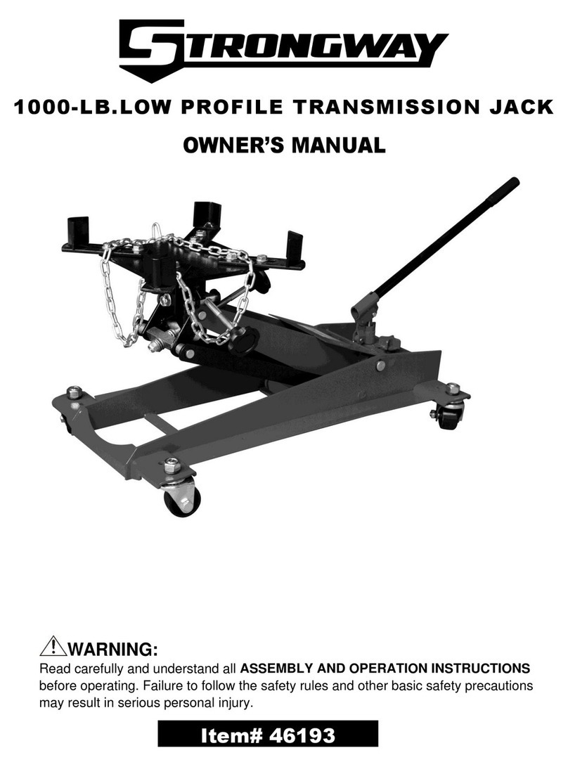
Strongway
Strongway 46193 owner's manual
Norco
Norco 72036D Setup, operating, maintenance instructions

MARTINS Industries
MARTINS Industries MFJ-20T manual
Napa
Napa Carlyle Tools 791-7100B operating manual
Sunex Tools
Sunex Tools 6613A Operating manual and parts list
