FATEK P5 Series Instruction manual

1
P5Series

2
Version
Date
Modification
V1.0.0
July 15,2015
First Draft
V1.0.1
July 16,2015
Update HMI Model Information (43 & C series)
V1.0.2
July 16,2015
Update Hitachi and Schneider
V1.0.3
July 17,2015
Add Siemens S7-1200 and fix maximum value of bitsInBytedeivce
V1.0.4
July 20,2015
Fix P5043 series
-Both Male Diagram
V1.0.5
Aug 10, 2015
Add Hitachi EHV Series( Ethernet )
V1.0.6
Sep 16, 2015
Add Allen-Bradley CompactLogix Series
V1.0.7
Dec 9, 2015
Add TAIE FY Series
V1.0.8
Dec 17, 2015
Add Delta DVP Series and AH500 series
V1.0.9
Jan 21, 2016
Add Panasonic FP Series
V1.0.10
Mar 7, 2016
Add Panasonic FP Series ( Ethernet )
V1.0.11
Mar 7, 2016
Add DB access function for SIEMENS S7 1200
V1.0.12
Apr 14, 2016
Add Mitsubishi FX5U Series
V1.0.13
Apr 28, 2016
Update Mitsubishi FX3U/FX2N driver for new type WX/WY/WM/WS
V1.0.14
May 24, 2016
Add YASKAWA Extended MEMOBUS
V1.0.15
Jun 20, 2016
Add Keyence KV-3000/5000/5500/7500 (ethernet) and
KV-L21V/3000/5000/5500
V1.0.16
Jul 6, 2016
Add Allen-Bradley SLC and MicroLogix Series
V1.0.16
Jul 15, 2016
Update KV-Nano (host link)
V1.0.17
Nov 25 2016
Add QSeries-Serial Communication, Q/L Series-ENET and
Update FBe(PLC setting)
V1.0.17
Nov 29 2016
Add Omron SYSMAC CP Series Ethernet and
Update Omron SYSMAC CP Series(PLC setting),Omron SYSMAC CS/CJ
Series(PLC setting), Omron SYSMAC CS/CJ Series Ethernet(PLC setting)
V1.0.17
Dec 2 2016
Update Siemens S7-200 SMART(PLC setting), Schneider MODBUS
RTU/TCP (PLC setting), Allen-Bradley SLC Series(PLC setting)
V1.0.17
Dec 7 2016
Update Taiwan Instrument & Control Co., Ltd FY Series(PLC setting)
Delta DVP Series(PLC setting), YASKAWA Extended MEMOBUS(PLC
setting)
V1.0.17
May 17, 2017
Add FBs/B1/B1z/HB1 (UDP), Omron SYSMAC CPM Series,
MP Series Extension (Ethernet) , Beckhoff Automation
V1.0.17
Aug 11, 2017
Add Koyo, Siemens LOGO
1. HMI Model Serial Information .......................................................................................................4

3
2. PLC Connection ..............................................................................................................................6
2.1 FATEK Automation Corp. ....................................................................................................6
2.1.1 FBs/B1/B1z/HB1.....................................................................................................6
2.1.2 FBe........................................................................................................................11
2.1.3 FBs/B1/B1z/HB1 (TCP) .........................................................................................17
2.1.4 FBe (TCP) ..............................................................................................................20
2.1.5 FBs/B1/B1z/HB1 (UDP) ........................................................................................22
2.2 Mitsubishi.........................................................................................................................25
2.2.1 FX2N CPU ............................................................................................................. 26
2.2.2 FX2N-485BD .........................................................................................................29
2.2.3 FX3U CPU .............................................................................................................37
2.2.4 FX3U-485BD .........................................................................................................41
2.2.5 FX3U Ethernet ......................................................................................................48
2.2.6 FX5U-Serial........................................................................................................... 54
2.2.7 FX5U Ethernet ......................................................................................................63
2.2.8 QSeries-Serial Communication(Link Port)............................................................69
2.2.9 QSeries-Serial Communication(CPU Port) ...........................................................77
2.2.10 Q/L Series-ENET ...................................................................................................82
2.3 Omron ..............................................................................................................................86
2.3.1 Omron SYSMAC CP Series ....................................................................................86
2.3.2 Omron SYSMAC CP Series Ethernet .....................................................................91
2.3.3 Omron SYSMAC CS/CJ Series ...............................................................................94
2.3.4 Omron SYSMAC CS/CJ Series Ethernet ................................................................98
2.3.5 Omron SYSMAC CPM Series...............................................................................103
2.4 Siemens..........................................................................................................................107
2.4.1 Siemens S7-200 SMART .....................................................................................107
2.4.2 Siemens S7-200 SMART Ethernet ......................................................................113
2.4.3 Siemens S7-1200 Ethernet.................................................................................118
2.4.4 Siemens S7-200..................................................................................................122
2.4.5 Siemens LOGO....................................................................................................129
2.5 Hitachi ............................................................................................................................132
2.5.1 EHV Series ..........................................................................................................132
2.5.2 EHV Series ( Ethernet ).......................................................................................135
2.6 Schneider .......................................................................................................................136
2.6.1 MODBUS RTU.....................................................................................................136
2.6.2 MODBUS TCP .....................................................................................................140
2.7 Allen-Bradley..................................................................................................................142
2.7.1 CompactLogix/ControlLogix/FlexLogix Tag Series..............................................142

4
2.7.2 SLC series (EtherNet/IP) .....................................................................................146
2.7.3 SLC Series ...........................................................................................................150
2.7.4 MicroLogix Series (EtherNet/IP).........................................................................155
2.7.5 MicroLogix Series ...............................................................................................159
2.8 Taiwan Instrument & Control Co., Ltd............................................................................164
2.8.1 FY Series .............................................................................................................164
2.9 Delta...............................................................................................................................174
2.9.1 DVP Series ..........................................................................................................174
2.9.2 AH500 Series ......................................................................................................177
2.10 Panasonic .......................................................................................................................184
2.10.1 FP Series .............................................................................................................184
2.10.2 FP Series (Ethernet)............................................................................................188
2.11 YASKAWA........................................................................................................................190
2.11.1 Extended MEMOBUS .........................................................................................190
2.11.2 MP Series Extension (Ethernet) .........................................................................193
2.12 Keyence ..........................................................................................................................196
2.12.1 KV-3000/5000/5500/7500(Ethernet) ................................................................196
2.12.2 KV-L21V/3000/5000/5500 (host link) ................................................................201
2.12.3 KV-Nano (host link) ............................................................................................210
2.13 Beckhoff Automation.....................................................................................................214
2.13.1 Twincat(Ethernet) ..............................................................................................214
2.14 Koyo................................................................................................................................218
2.14.1 Direct..................................................................................................................218
1. HMI Model Serial Information
P5043S/P5043N/P5070VS/P5102VS
Serial Interface
COM1(RS-232[TXD,RXD]), COM2(RS-422/485),
COM3(RS-485)
Serial Layout
RS-232/
RS-422/
RS-485
PIN#
COM1
COM2
(RS-422)
COM2
(RS-485)
COM3

5
1
TX+
DATA+
2
RX
3
TX
4
RX+
5
GND
GND
GND
GND
6
TX-
DATA-
7
DATA+
8
DATA-
9
RX-
P5070S/ P5070N/ P5070N1/ P5102S/ P5102N/ P5102N1
Serial Interface
COM1(RS-232[TXD,RXD,RTS,CTS]),
COM3(RS-422/485), COM4(RS-485)
Serial Layout
RS-232
PIN#
COM1
1
2
RX
3
TX
4
5
GND
6
7
RTS
8
CTS
9
RS-422/
485
Old Model
PIN#
COM3
(RS-422)
COM3
(RS-485)
COM4

6
1
TX-
DATA-
2
TX+
DATA+
3
RX-
4
RX+
5
ISO_GND
6
7
DATA-
8
DATA+
9
New Model
PIN#
COM3
(RS-422)
COM3
(RS-485)
COM4
1
DATA+
2
DATA-
3
ISO_GND
ISO_GND
ISO_GND
4
RX+
5
RX-
6
TX+
DATA+
7
TX-
DATA-
2. PLC Connection
2.1 FATEK Automation Corp.
FBs/B1/B1z/HB1
2.1.1.1 Communication Setting
Item
Default Setting
Remark
Signal Level
RS232
Baud Rate
9600
Data Length
7
Stop Bit
1
Parity
Even
PLC Station No.
1
Must match PLC

7
port setting
Communication Method
FATEK Communication
Protocol
2.1.1.2 Memory Resource Review
Device
Data Bits
Address
Format
Min.
Max.
Description
X
1
DDDD
0
255
Input Discrete
Y
1
DDDD
0
255
Output Relay
M
1
DDDD
0
2001
Internal Relay
S
1
DDDD
0
999
Step Relay
T
1
DDDD
0
255
Timer Discrete
C
1
DDDD
0
255
Counter Discrete
WX
16
DDDD
0
255
Input Discrete
WY
16
DDDD
0
255
Output Relay
WM
16
DDDD
0
2001
Input Relay
WS
16
DDDD
0
999
Step Relay
RT
16
DDDD
0
255
Timer Register
RC
16
DDDD
0
199
Counter Register
DRC
32
DDDD
200
255
Counter Register
R
16
DDDD
0
8071
Data Register
D
16
DDDD
0
4095
Data Register
F
16
DDDD
0
8191
File Register
2.1.1.3 Connecting to PLC
Configuring the PLC
Use the application WinProLadder (ver. 3.25) to configure the serial port of the PLC.
Connect the PLC to a computer. In the application, under the PLC tab, select the
On-Line option. In the dialog, select RS232 for the Connection Name and press ‘Edit’.
Within the edit dialog, select the port number the PLC is connected to. Press OK to
confirm the settings.

8
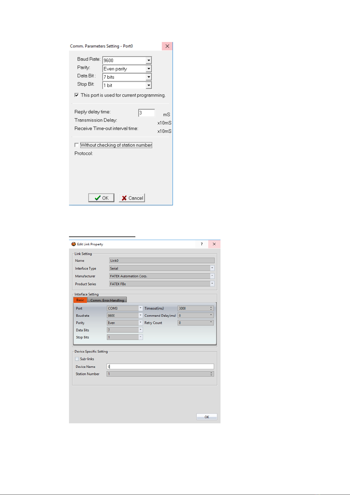
Under the PLC tab, select the Setting option and choose Port 0. Here, the Baud rate
and other parameters of the serial port can be configured.
Note: For more detailed information please refer to the PLC manual.
Connecting PLC to HMI

9
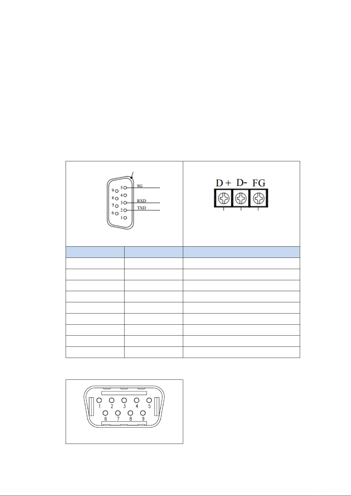
Within the Link configuration window in FvDesigner:
Under Interface Type select Serial
Under Manufacturer select FATEK Automation Corp
Under Product Series select FATEK FBs/B1/B1z/HB1
Under Port select COM1
Verify the other parameters are consistent with the settings on the PLC.
2.1.1.4 Wiring Diagrams
HMI COM1 Pinout
*Looking into COM1 Port
PIN#
COM1 (RS232)
1
2
RX
3
TX
10
4
5
GND
6
7
RTS
8
CTS
9
PLC RS232 Pinout
*Looking into PLC
PIN#
Signal
1
2
GND
3
TX
4
RX
All P5 Series
HMI COM1
PLC RS232 Port
2 RX
3 TX
3 TX
4 RX
5 GND
2 GND
Wiring Diagrams:All P5Series

11
FBe
2.1.2.1 Communication Setting
Item
Default Setting
Remark
Signal Level
RS232 / RS485
Baud Rate
9600
Data Length
7
Stop Bit
1
Parity
Even
PLC Station No.
1
Must match PLC
port setting
Communication Method
FATEK Communication
Protocol
2.1.2.2 Memory Resource Review
Device
Data Bits
Address
Format
Min.
Max.
Description
X
1
DDDD
0
255
Input Discrete
Y
1
DDDD
0
255
Output Relay
M
1
DDDD
0
2001
Internal Relay
S
1
DDDD
0
999
Step Relay
T
1
DDDD
0
255
Timer Discrete
C
1
DDDD
0
255
Counter Discrete
WX
16
DDDD
0
255
Input Discrete

12
WY
16
DDDD
0
255
Output Relay
WM
16
DDDD
0
2001
Input Relay
WS
16
DDDD
0
999
Step Relay
RT
16
DDDD
0
255
Timer Register
RC
16
DDDD
0
199
Counter Register
DRC
32
DDDD
200
255
Counter Register
R
16
DDDD
0
8071
Data Register
D
16
DDDD
0
4095
Data Register
2.1.2.3 Connecting to PLC
Configuring the PLC
Use the application WinProLadder (ver. 3.25) to configure the serial port of the PLC.
Connect the PLC to a computer. In the application, under the PLC tab, select the
On-Line option. In the dialog, select RS232 for the Connection Name and press ‘Edit’.
Within the edit dialog, select the port number the PLC is connected to. Press OK to
confirm the settings.
Under the PLC tab, select the Setting option and choose Port 0. Here, the Baud rate
and other parameters of the serial port can be configured.
13
Note: For more detailed information please refer to the PLC manual.
Connecting PLC to HMI
Within the Link configuration window in FvDesigner:
14
Under Interface Type select Serial
Under Manufacturer select FATEK Automation Corp.
Under Product Series select FATEK FBe
Under Port select the port corresponding to the connection to the PLC
Verify the other parameters are consistent with the settings on the PLC
2.1.2.4 Wiring Diagrams
Note: The connections were made between the HMI and the FB-DTBR-E module. The
module provides ports for each connection type.
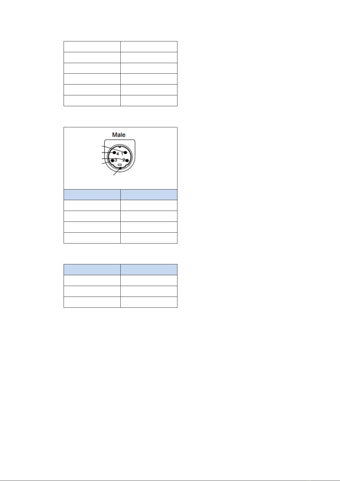
PLC RS232 Pinout
*Looking into port0
PLC RS485 Pinout
PIN#
Port 0 (RS-232)
Port 2 (RS-485)
1
DATA+
2
TXD
DATA-
3
RXD
FG
4
5
GND
6
7
8
9
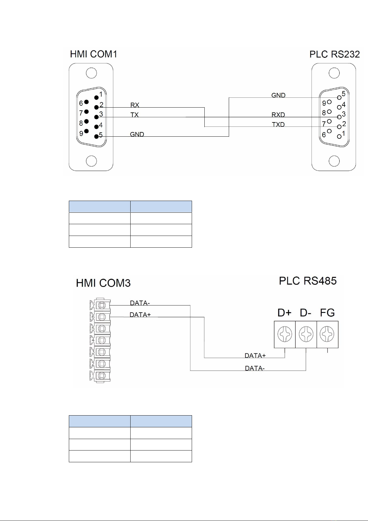
HMI COM1 Pinout
*Looking into COM1 Port

15
PIN#
COM1 (RS232)
1
2
RX
3
TX
4
5
GND
6
7
RTS
8
CTS
9
HMI COM3 Pinout
*Looking into HMI Device
PIN#
COM3
(RS-422/RS-485)
1
2
3
ISO_GND
4
5
6
DATA+
7
DATA-
All P5 Series
HMI COM1
PLC RS232 Port
2 RX
2 TXD
3 TX
3 RXD
5 GND
5 GND
Wiring Diagrams:All P5Series
16
P5070S/ P5070N/ P5070N1/ P5102S/ P5102N/ P5102N1
HMI COM3
PLC RS485 Port
6 DATA+
DATA+
7 DATA-
DATA-
Wiring Diagrams: P5070S/ P5070N/ P5070N1/ P5102S/ P5102N/ P5102N1
P5043S/P5043N/P5070VS/P5102VS
HMI COM2
PLC RS485 Port
1 DATA+
DATA+
6 DATA-
DATA-
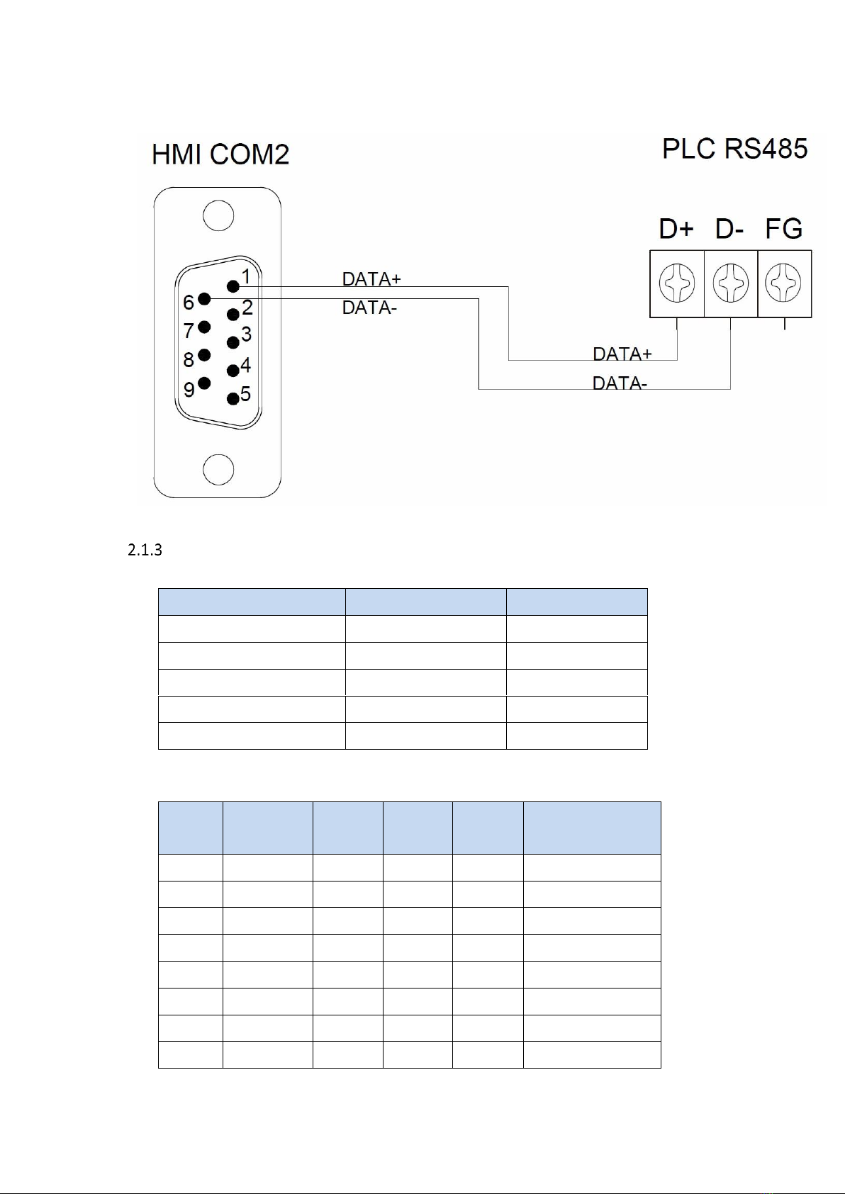
17
Wiring Diagrams:P5043S/P5043N/P5070VS/P5102VS
FBs/B1/B1z/HB1 (TCP)
2.1.3.1 Communication Setting
Item
Default Setting
Remark
Signal Level
Ethernet
Internet Protocol
192.168.1.3
Port
500
PLC Station No.
0
Communication Method
TCP
2.1.3.2 Memory Resource Review
Device
Data Bits
Address
Format
Min.
Max.
Description
X
1
DDDD
0
255
Input Discrete
Y
1
DDDD
0
255
Output Relay
M
1
DDDD
0
2001
Internal Relay
S
1
DDDD
0
999
Step Relay
T
1
DDDD
0
255
Timer Discrete
C
1
DDDD
0
255
Counter Discrete
WX
16
DDDD
0
255
Input Discrete
WY
16
DDDD
0
255
Output Relay

18
WM
16
DDDD
0
2001
Input Relay
WS
16
DDDD
0
999
Step Relay
RT
16
DDDD
0
255
Timer Register
RC
16
DDDD
0
199
Counter Register
DRC
32
DDDD
200
255
Counter Register
R
16
DDDD
0
8071
Data Register
D
16
DDDD
0
4095
Data Register
F
16
DDDD
0
8191
File Register
2.1.3.3 Connecting to HMI
Configuring IP Address on PLC
Use the application FATEK Ethernet Module Configuration Tool to configure the IP
address of the PLC. Connect an Ethernet cable to the PLC. Under Attached Media,
select LAN and press scan.
Select the PLC to connect to and right click or press Properties to change the IP.
Note: The default IP address for the PLC has 1 for its third octet. If the IP address of the
computer has a different number at that position, the PLC will not show up in the scan.
Configure network settings on the computer to be able to see the PLC in the local
network.
In the dialog window, the IP address and other parameters of the PLC can be
configured. In the Service Ports tab, the port number of the PLC can be changed.

19
Note: For more detailed information please refer to the PLC manual.
Connecting PLC to HMI
Within the Link configuration window in FvDesigner:
Under Interface Type select Ethernet
Under Manufacturer select FATEK Automation Corp
Under Product Series select FATEK FBs/B1/B1z/HB1 (TCP)

20
Use the IP address and port number assigned on the PLC
FBe (TCP)
2.1.4.1 Communication Setting
Item
Default Setting
Remark
Signal Level
Ethernet
Internet Protocol
192.168.1.3
Port
500
PLC Station No.
0
Communication Method
TCP
2.1.4.2 Memory Resource Review
Device
Data Bits
Address
Format
Min.
Max.
Description
X
1
DDDD
0
255
Input Discrete
Y
1
DDDD
0
255
Output Relay
M
1
DDDD
0
2001
Internal Relay
S
1
DDDD
0
999
Step Relay
T
1
DDDD
0
255
Timer Discrete
C
1
DDDD
0
255
Counter Discrete
WX
16
DDDD
0
255
Input Discrete
WY
16
DDDD
0
255
Output Relay
WM
16
DDDD
0
2001
Input Relay
WS
16
DDDD
0
999
Step Relay
RT
16
DDDD
0
255
Timer Register
RC
16
DDDD
0
199
Counter Register
DRC
32
DDDD
200
255
Counter Register
R
16
DDDD
0
8071
Data Register
D
16
DDDD
0
4095
Data Register
2.1.4.3 Connecting to HMI
Configuring IP Address on PLC
Use the application FATEK Ethernet Module Configuration Tool to configure the IP
address of the PLC. Connect an Ethernet cable to the PLC. Under Attached Media,
select LAN and press scan.
This manual suits for next models
10
Table of contents
Other FATEK Industrial Equipment manuals


