FATEK P5150NH User manual

1
Thank you for purchasing FATEK HMI. Before installing or operating the unit, please read
this installation guide carefully to ensure correct use.
1. Safety Precautions (Read these precautions before use.)
1.1 General
Unpack and check the delivery for transportation damage. If any damage or
deformation is found, please notify the supplier.
The supplier is not responsible for the disassembled, altered or modified device.
Never allow fluid or any conductive particles to enter into the HMI. Otherwise,
it may damage the HMI, cause fire or malfunction.
Only qualified personnel may install the HMI, perform maintenance and
inspection.
The liquid crystal inside the LCD panel is a hazardous substance. If the panel
is damaged, avoid contact with the leaked liquid crystal. If the liquid crystal
spills on clothing or skin, use soap and wash off thoroughly. In case of eye
contact the liquid, hold the eye open, flush with plenty water and get medical
attention as soon as possible.
Do not touch any terminals while the power is on. Otherwise, it may cause
injury due to electrical shock.
Disconnect the power supply before installing the HMI, do wiring operation,
perform maintenance or inspection. Otherwise, it may cause damage or
electrical shock.
1.2 Installation
The installation may be carried out by qualified personnel only.
Install the HMI according to the installation procedures.
Check the power source voltage is within the specified range and the polarity
is correct before connecting the HMI.
Keep signal and power supply cables away from high-voltage, large-current
carrying cables.
P5150NH HMI Installation Guide

2
Caution
Make sure the HMI is properly grounded to prevent electrical
shock, fire or malfunction.
HMI unit and other equipment should have the same electrical grounding
(reference voltage level), otherwise communication errors may occur.
1.3 Operation
Do not use sharp objects or excessive force to press the touch screen. This
may damage the touch screen.
Do not use the output signal of the device as any safety function or system
emergency stop. It may result in personal injury or equipment damage if a
malfunction of the touch occurs.
1.4 Maintenance and Service
The agreed guarantee applies.
Only qualified personnel should make repairs and perform maintenance.
Disconnect the device from the power supply before carrying out cleaning or
maintenance.
Clean the front panel with a soft cloth and mild detergent.
Please use original replacement spare parts or accessories.
3
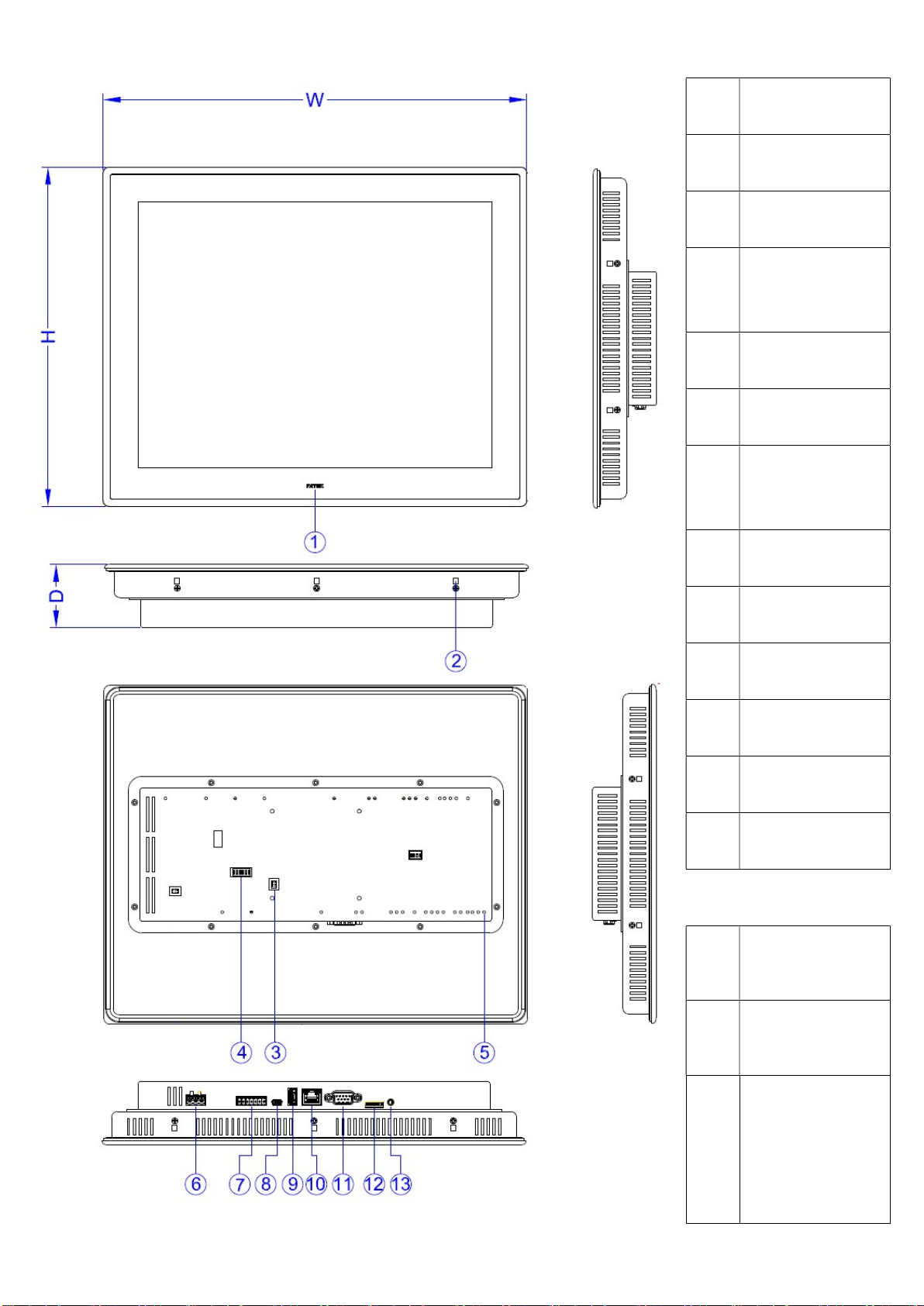
2. Part Names and Dimensions
①
Power Indicator
Light
②
Mounting Hole
③
HB1 PLC
Connector
④
COM3/COM4
Termination
Switch
⑤
HB1 PLC
Screw Hole
⑥
Power
Connector
⑦
COM3/COM4:
Pluggable
Terminal Block
⑧
Mini USB
Connector
⑨
USB Connector
⑩
Ethernet RJ45
Connector
⑪
COM1: DB-9
Male Connector
⑫
Micro-SD Card
Slot
⑬
Audio Phone
Jack
W 365 mm
H 292 mm
D 54.7 mm

4
3. Specifications
Model P5150NH
UL 61010-1
Technical
Consideration
Type of item tested Control
Product Description Operator Panel
Connections to mains
supply Permanent
Overvoltage category II
Pollution degree 2
Means of Protection Class III
Environmental conditions
Operating Temp. 0~50°C
Storage Temp. -20 ~ 60 ℃
For use in wet locations
No
Equipment mobility Built in
Operating conditions Continuous
Overall size 365 x 292 x 54.7 (mm)
Weight 2950 (g)
Marked degree of
protection
Front panel: IP65 / Rear Case: IP20 to IEC 60529
Type 1 to UL 50E
Equipment classification Industrial, Professional, Commercial
Equipment class Class III
Equipment type Permanently connected, Fixed
I/O Port
Serial 1 Connector: D-Sub 9-Pin
COM1: RS-232 (4W)
Serial 2
Connector: Pluggable Terminal Block
COM3: RS-422/485
COM4: RS-485
LAN 10M/100M
USB USB2.0 Type-A (Host)x1
USB2.0 Type mini-B (Device)x1
Micro SD Yes
Audio Yes
PLC Extension HB1 main units + B1 extension modules
Termination
Switch Yes (For RS-422/485)
Power
Power Input 24VDC
±
20% (Isolated Power)
Consumption 833mA@24VDC
Insulation 50MΩ at 500VDC
Environment
Relative Humidity 10%~90%@ 40°C (non-condensing)
Withstand Voltage AC500V/20mA/1 Min. (between charger & FG terminals)
Vibration
5 to 9Hz Half-amplitude: 3.5mm
9 to 150 Hz Constant acceleration: 19.6m/s2 (2G)
3 directions of X, Y, Z: 10times (IEC61131-2 complaints)
Noise Suppression 1000Vp-p, width 1us, rising time 1ns
Grounding Resistance Below 100Ω
Dimension Cut-out 351 x 278 (mm)

5
4. Unpacking the Unit
FATEK HMI x1
Hook and Screw x10
FATEK PLC
Connector x1
A4 Double-sided Installation Guide x1
Power Connector x1
Pluggable Terminal
Block x1
5. Installation Procedures
Push the HMI into the cutout
until the
waterproof ring contacts the plate.
Insert a hook into each mounting hole
on the
HMI, and then tighten the screws
evenly with a moderate torque.
Failure to tighten the screws may cause
the HMI to fall, malfunction or short-
circuit. Excessive
tightening may cause
deformation. The necessary torque is
about 0.16N·m.
6
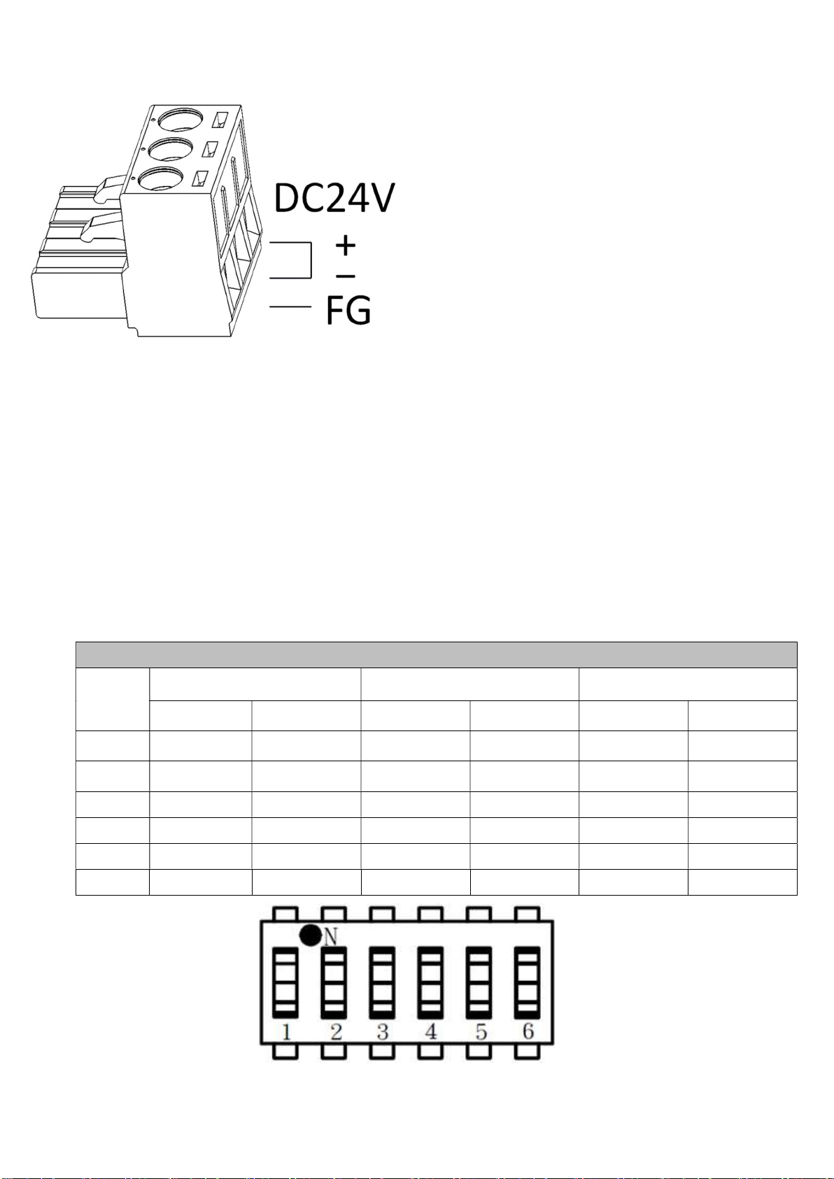
6. Power Connection
Be sure to connect the ground FG
terminal to a class-
3 ground (Ground
resistance should not exceed 100Ω).
Try to make the ground wire
as short
as possible.
Use 28–12 AWG (0.5–1.5 mm2)
wire
for the power connections.
7. Termination Switch
P5150NH HMI has a built-in termination resistor switch.
To enable or disable the termination resistor please follow the configuration
shown in the table below. The termination switch is for COM3 [RS-422 / RS-
485] and COM4 [RS-485].
Configuration of Termination Resistor Switch.
Termination Resistor
No. COM3 [RS-422] COM3 [RS-485] COM4 [RS-485]
Enable Disable Enable Disable Enable Disable
6 OFF OFF OFF OFF ON OFF
5 OFF OFF OFF OFF ON OFF
4 ON OFF ON OFF OFF OFF
3 ON OFF ON OFF OFF OFF
2 ON OFF OFF OFF OFF OFF
1 ON OFF OFF OFF OFF OFF

7
8. Pin-out of COM Ports
DB-9 Male Connector
PIN# COM1
[RS-232]
1 NC*1
2 RX
3 TX
4 NC
5 GND
6 NC
7 RTS
8 CTS
9 NC
*1 NC: No Connection
P
luggable Terminal Block
PIN# COM3
[RS-422]
COM3
[RS-485]
COM4
[RS-485]
1 NC NC DATA+
2 NC NC DATA-
3 GND GND GND
4 RX+ NC NC
5 RX- NC NC
6 TX+ DATA+ NC
7 TX- DATA- NC
8
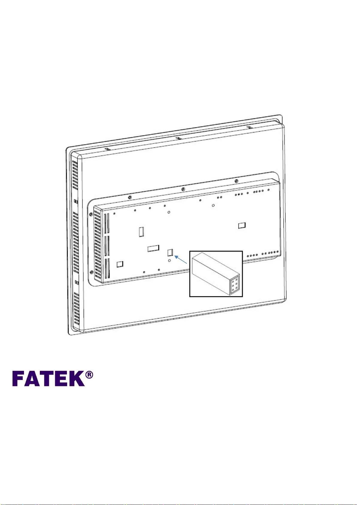
9. PLC Extension Tips
For compact size and saving space, using FATEK HB1 main units + B1
extension modules is recommended.
To connect FATEK PLC main unit, first use the FATEK PLC connector to
connect the main unit and then insert into the HB1 connector hole on the back
cover of the HMI to complete the connection.
26FL., NO. 29, SEC. 2, JUNGJENG E. RD.,
DANSHUEI DIST., NEW TAIPEI CITY 25170, TAIWAN, R.O.C
TEL : +886-2-2808-2192
FAX : +886-2-2809-2618
E-mail : sales@fatek.com
tech@fatek.com
Website : www.fatek.com
AUTOMATION CORP
ORATION
Table of contents
Other FATEK Industrial Equipment manuals


