Faudi AFGUARD AFG Series User manual
Version 2.2
Operating instructions
AFGUARD®
Zone 0/1 type
Page: 1
of: 47
FAUDI Aviation GmbH, Scharnhorststraße 7 B, D-35260 Stadtallendorf
BA_AFGUARD_Ex_rev2.2_Englisch
Sensor for the measurement of free water in Jet Fuel

Version 2.2
Operating instructions
AFGUARD®
Zone 0/1 type
Page: 2
of: 47
FAUDI Aviation GmbH, Scharnhorststraße 7 B, D-35260 Stadtallendorf
BA_AFGUARD_Ex_rev2.2_Englisch
Contact address of manufacturer:
FAUDI Aviation GmbH
Scharnhorststrasse 7 B
D- 35260 Stadtallendorf
Germany
Telefon: +49 6428 4465 - 275
Fax: +49 6428 4465 - 221
Mail: Sen[email protected]om
Web: www.faudi-aviation.com
Table of contents Page
1Safety instructions................................................................................................ 4
1.1 Designated use.................................................................................................... 5
1.2 Installation, Commissioning and Operation.......................................................... 5
1.3 Operational safety................................................................................................ 5
1.4 Return.................................................................................................................. 5
2Identification......................................................................................................... 7
2.1 Product structure.................................................................................................. 7
2.2 Scope of delivery ................................................................................................10
3Installation and dismantling.................................................................................11
3.1 Incoming acceptance, transport, storage.............................................................11
3.2 Installation conditions..........................................................................................12
3.2.1 Dimensions........................................................................................................12
3.2.2 Mounting Position...............................................................................................12
3.3 Thread for AFGUARD installation .......................................................................13
3.3.1 Installation place ................................................................................................13
3.3.2 Procedure for proper AFGUARD®installation.....................................................14
3.3.3 AFGUARD orientation in the pipe section...........................................................18
3.3.4 Measuring system..............................................................................................18
3.3.5 Installing a measuring point................................................................................19
3.4 Installation examples...........................................................................................20
3.4.1 Measuring at the inlet and / or outlet of Filter Vessels ........................................20
3.5 Check of correct assembly..................................................................................21
3.6 Dismantling.........................................................................................................21
4Cabling................................................................................................................22
4.1 Direct connection to isolated converter with power supply...................................22
5Operation............................................................................................................23
5.1 Assembly instructions of the AFGUARD®...........................................................23
5.2 Mode of Operation..............................................................................................24
5.3 Signal output.......................................................................................................25
5.4 Calibration...........................................................................................................25
6Commissioning ...................................................................................................27
6.1 Check of Installation and function........................................................................27
7Loop check .........................................................................................................28
8Maintenance .......................................................................................................29
8.1 Cleaning of the AFGUARD®................................................................................29
9Accessories ........................................................................................................30
9.1 Connection accessories......................................................................................30
9.2 Installation accessories.......................................................................................33
10 Trouble-shooting.................................................................................................34
10.1 Trouble-shooting instructions..............................................................................34
10.2 Sensor checks ....................................................................................................34
10.3 Spare parts.........................................................................................................34
10.4 Return.................................................................................................................34

Version 2.2
Operating instructions
AFGUARD®
Zone 0/1 type
Page: 3
of: 47
FAUDI Aviation GmbH, Scharnhorststraße 7 B, D-35260 Stadtallendorf
BA_AFGUARD_Ex_rev2.2_Englisch
10.5 Disposal..............................................................................................................34
11 Technical Data....................................................................................................35
11.1 Input....................................................................................................................35
11.2 Ambient conditions..............................................................................................35
11.3 Performance and parameter ...............................................................................35
11.4 Process conditions..............................................................................................35
11.5 Layout.................................................................................................................35
12 EC-Type Examination Certificate (Original).........................................................37
12.1 EC-Type Examination Certificate (Tranlsation)....................................................40
12.2 PESO Certificate for India...................................................................................43
12.3 EG-Konformitätserklärung –EC Declaration of conformity..................................44
13 Issues and solutions............................................................................................45
14 Declaration of decontamination...........................................................................47
Version 2.2
Operating instructions
AFGUARD®
Zone 0/1 type
Page: 4
of: 47
FAUDI Aviation GmbH, Scharnhorststraße 7 B, D-35260 Stadtallendorf
BA_AFGUARD_Ex_rev2.2_Englisch
1 Safety instructions
This manual provides installation, operation and routine maintenance instructions for
the FAUDI Aviation AFGUARD®free water sensor.
Read this manual and ensure that you fully understand its content before you attempt
to install, use or maintain the AFGUARD®free water sensor.
Important safety information is highlighted in this manual as WARNINGs and CAUTIONs.
The AFGUARD®is an intrinsically safe Sensor, suitable for the needs of field and laboratory
analysis of the content of free water in Jet fuel.
Work on electrical equipment is only to be carried out by trained specialists as per the
regulations currently in force.
Attention must be paid to the requirements of VDE 0100 when setting high-power electrical
units with nominal voltages of up to 1000V, together with the associated standards and
stipulations.
Check the details on the type plate to ensure that the equipment is connected up to the
correct mains voltage.
Protect against touching dangerously high electrical voltages. Before opening the equipment,
it must be switched off and hold no voltages. This also applies to any external control circuits
that are connected.
the equipment is only to be set within the permitted range of temperatures and pressures.
For use in hazardous area observe the relevant national and international instructions and
regulations.
Check that the location is weather-protected. It is recommended that the AFGUARD®should
not be subjected to either direct rain or moisture.
Installation, maintenance, monitoring and any repairs may only be done by authorised
personnel with respect to the relevant stipulations.
All changes of the standard analyser with parts which are not specified or approved by
FAUDI Aviation Sensor GmbH as well as repair and service with not specified parts mean a
loss of the Ex-Certificate.
In case of doubt, please turn directly to FAUDI Aviation Sensor GmbH respectively to your
FAUDI Aviation Distributor or Service organisation.
The AFGUARD®is certified through DEKRA Exam in Bochum, authorized company for
official approval of electric equipment in Germany.
Detailed information and a copy of the certificate are attached to this operating manual.
Installation and operation of the analyser has to be done corresponding to the conditions in
the Ex-Certificate (see appendix). Only in this case, the reliability of operation in hazardous
area can be guaranteed.
E
For the AFGUARD®Ex-Version the electrical standard of electrical equipment corresponds
to the safety regulations concerning the:
oEN 60079-0 (Allg. Anforderungen);
oEN 60079-11 (Geräteschutz durch Eigensicherheit „i“);
oEN 60079-18 Geräteschutz durch Vergusskapselung „m“;
oEN 60079-26 (Geräteschutz der Betriebsmittel für Gruppe II Kategorie 1 G);
oEN 60079-28 (Schutz von Einrichtungen und Übertragungssystemen, die mit
optischer Strahlung arbeiten)
For operation of the equipment in hazardous areas group II category 2, Explosion group
“IIB”, Temperature class T4 with ambient temperature range from – 30 °C Ta+60 °C.

Version 2.2
Operating instructions
AFGUARD®
Zone 0/1 type
Page: 5
of: 47
FAUDI Aviation GmbH, Scharnhorststraße 7 B, D-35260 Stadtallendorf
BA_AFGUARD_Ex_rev2.2_Englisch
1.1 Designated use
The AFGUARD®is suitable for continuous measurement of free water in Jet Fuel.
Typical applications of the AFGUARD®are:
Measuring the content of free water at the inlet of refuelling units and filter water separators
Measuring the free water content at the outlet of FWS Filter Water Separators.
Functioning control of Monitor elements measuring the content of the free water at the inlet
and outlet of monitor vessels.
Control, measurement and adjustment of additive dosage compared to the free water content
in Jet Fuels.
Any other use than the one described here compromises the safety of persons and the entire
measuring system and is, therefore not permitted.
The manufacturer is not liable for damage caused by improper or non-designated use.
1.2 Installation, Commissioning and Operation
Please note:
Installation, electrical connection, commissioning, operation and maintenance of the
measuring system must only be carried out by trained technical personnel.
The technical personnel must be authorised for the specified activities by the system
operator.
Technical personnel must have read and understood these Operating Instructions and must
adhere to them.
Before commissioning the entire measuring point, check all the connections for correctness.
Ensure that electrical cables and hose connections are not damaged.
Do not operate damaged products and secure them against unintentional commissioning.
Mark the damaged product as being defective.
Measuring point faults may only be rectified by authorised and specially trained personnel.
If faults cannot be rectified, the products must be taken out of service and secured against
unintentional commissioning.
Repairs not described in these Operating Instructions may only be carried out at the
manufacturer or by a designated service organisation.
1.3 Operational safety
The sensor has been designed and tested according to the state of the art and left the
factory in perfect functioning order.
Relevant regulations and European standards have been met.
As the user, you are responsible for complying with the following safety conditions:
Installation instructions
Local prevailing standards and regulations.
1.4 Return
If the device requires repair, please send it in cleaned condition to the appropriate sales
centre. Please use the original packaging.
Please enclose the completed "Declaration of Decontamination" (copy the responsible pages
out of chapter 12 of the Operating Instructions) with the packaging and in addition, the
shipping documents.
No repair is possible without the completed "Declaration of Decontamination"!
For optimized shipment –please contact FAUDI-Aviation Shipping department in front of
shipment.

Version 2.2
Operating instructions
AFGUARD®
Zone 0/1 type
Page: 6
of: 47
FAUDI Aviation GmbH, Scharnhorststraße 7 B, D-35260 Stadtallendorf
BA_AFGUARD_Ex_rev2.2_Englisch
Notes on safety icons and symbols
Warning!
This symbol alerts you to possible faults which can end in explosion. They
can cause serious damage to the instrument or to persons if ignored.
Warning!
This symbol alerts you to hazards. They can cause serious damage to the
instrument or to persons if ignored.
Caution!
This symbol alerts you to possible faults which could arise from incorrect
operation. They could cause damage to the instrument if ignored.
Note!
This symbol indicates important items of information.
Version 2.2
Operating instructions
AFGUARD®
Zone 0/1 type
Page: 7
of: 47
FAUDI Aviation GmbH, Scharnhorststraße 7 B, D-35260 Stadtallendorf
BA_AFGUARD_Ex_rev2.2_Englisch
2 Identification
2.1 Product structure
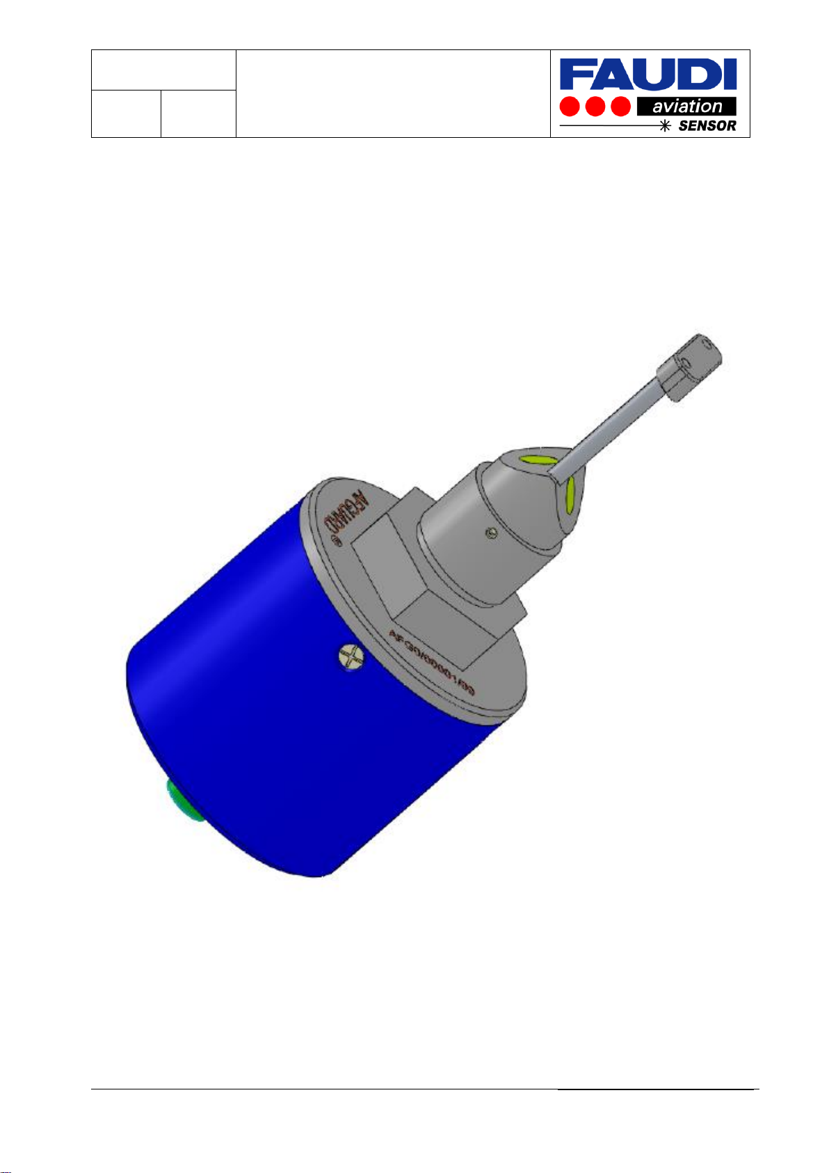
The AFGUARD®is marked with the following, permanently identification marking.
At the head of the Sensor you will find the engraved name AFGUARD®and serial no. –see
attached picture.
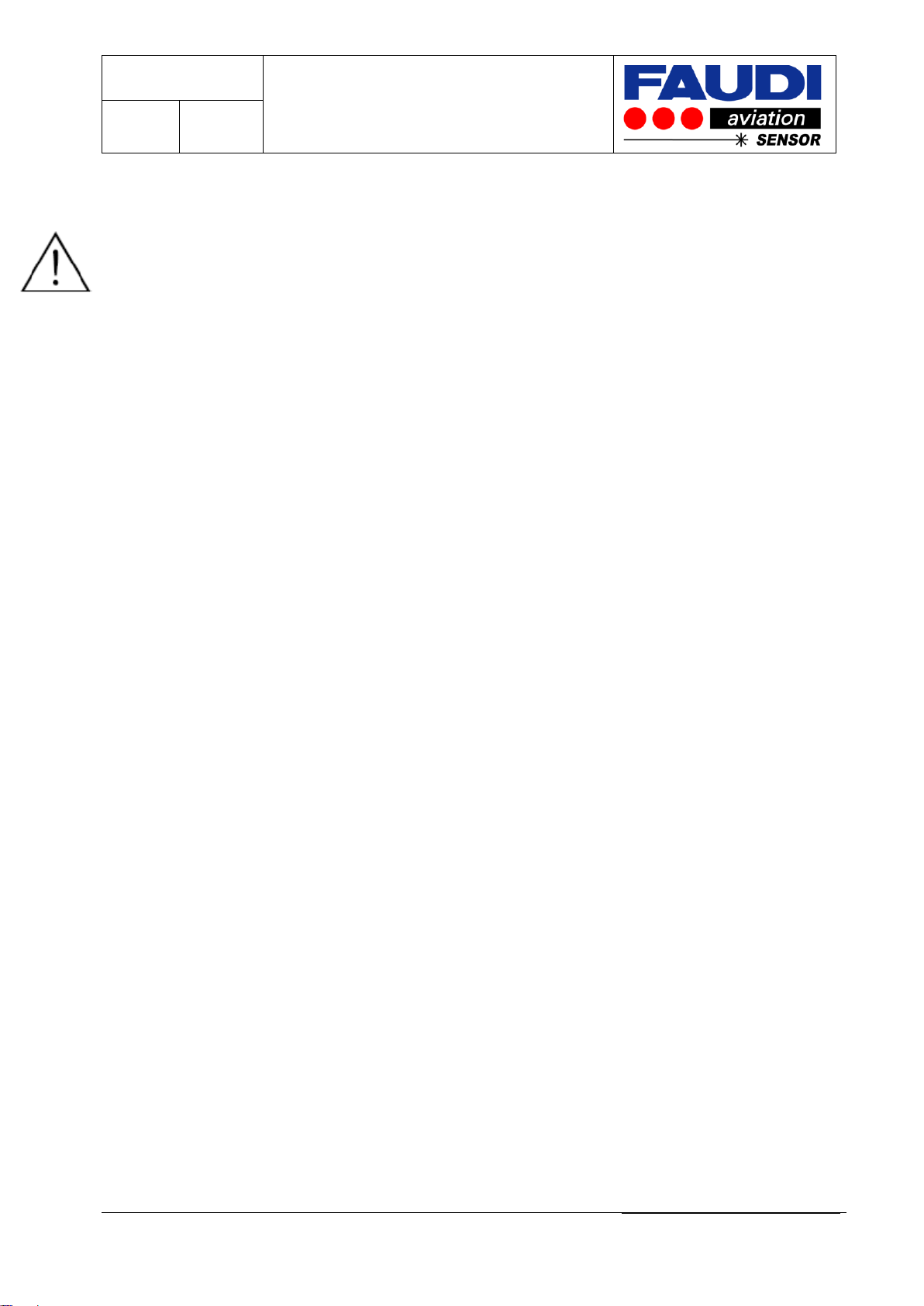
The Series No is the distinctive feature to distinguish the AFGUARD®from each other. It is
born according the following attributes
Engraved Serial No: AFGX/XXXXX/a
Year of construction
Serial number
(5 digits)
0 = Ex-Version zone 0/1
1 = Non-Ex-Version
2 = Ex-Version zone 2
Name
Brand name
AFGUARD®-SENSOR
Serial No
AFG0/00001/a

Version 2.2
Operating instructions
AFGUARD®
Zone 0/1 type
Page: 8
of: 47
FAUDI Aviation GmbH, Scharnhorststraße 7 B, D-35260 Stadtallendorf
BA_AFGUARD_Ex_rev2.2_Englisch
Additional to the marking of name and serial No. there is an engraved nameplate on the
housing of the AFGUARD®with additional information:
Picture: Nameplate of a Hazardous Area approved Version of the AFGUARD® for
hazardous Area Zone 0/1
The Ex-Version has a complimentary engraved Serial No on the Sensor head.
Picture: Nameplate of a Non-Ex-Version of the AFGUARD®
Picture: Nameplate of a Hazardous area approved version of the AFGUARD® for
hazardous area Zone 2
AFGUARD®
Serial No: AFG1/00001/a
Safe Area
Operating Temp. : - 30 °C ≤ Ta≤ + 60 °C
Supply and Signal circuit:
Maxima : Ui30 V ; Ii100 mA ; Pi750 mW
Manufactured by:
Contact
FAUDI Aviation Sensor GmbH
Fax
+49 6428 4465-221
Scharnhorststraße 7 B
Email
sensor@faudi-aviation.com
Voltage:
15 - 30 V DC
D 35260 Stadtallendorf
Web
www.faudi-aviation.com
Signal output
4 –20 mA
Germany
AFGUARD®
Serial No: AFG2/00001/a
BVS 09 ATEX E 115
C–0158
E
II 3 G Ex ic IIA T3
Operating Temp. : - 30 °C ≤ Ta≤ + 60 °C
Supply and Signal circuit for:
Ex ic IIA
Maxima : Ui30 V ; Ii100 mA ; Pi750 mW
Manufactured by:
Contact
FAUDI Aviation Sensor GmbH
Fax
+49 6428 4465-221
Scharnhorststraße 7 B
Email
sensor@faudi-aviation.com
Voltage:
15 - 30 V DC
D 35260 Stadtallendorf
Web
www.faudi-aviation.com
Signal output
4 –20 mA
Germany

Version 2.2
Operating instructions
AFGUARD®
Zone 0/1 type
Page: 9
of: 47
FAUDI Aviation GmbH, Scharnhorststraße 7 B, D-35260 Stadtallendorf
BA_AFGUARD_Ex_rev2.2_Englisch
Beside Serial No and nameplate the readout of the individual configuration can be done by
the product key.
Productkey
AFG
x
x
x
x
x
x
x
0
Name
AFG
Version
Ex-Version 1
0
Non-Ex-
Version
1
Ex-Version 2
2
Measurement range
0 –50 ppm
a
On request
0 –100 ppm
b
Language
German
a
English
b
Variants:
Following variants are availlable:
Ex - Variants : Serie, Non-Ex-Version; Ex-Version Zone 0/1 and Zone 2
Intended use : Civil, Military, Offshore
Power supply
Direct current voltage: DC 24 V,
Measurement ranges: 0 to 50 ppm or 0 to 100 ppm on request
Languages: German, English…
Version 2.2
Operating instructions
AFGUARD®
Zone 0/1 type
Page: 10
of: 47
FAUDI Aviation GmbH, Scharnhorststraße 7 B, D-35260 Stadtallendorf
BA_AFGUARD_Ex_rev2.2_Englisch
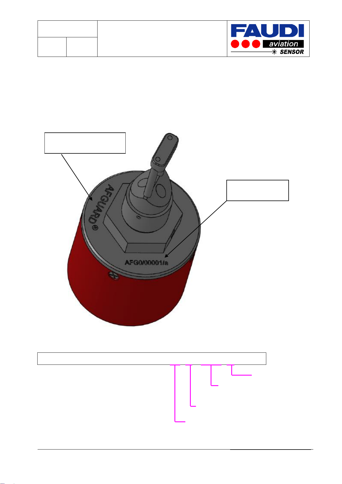
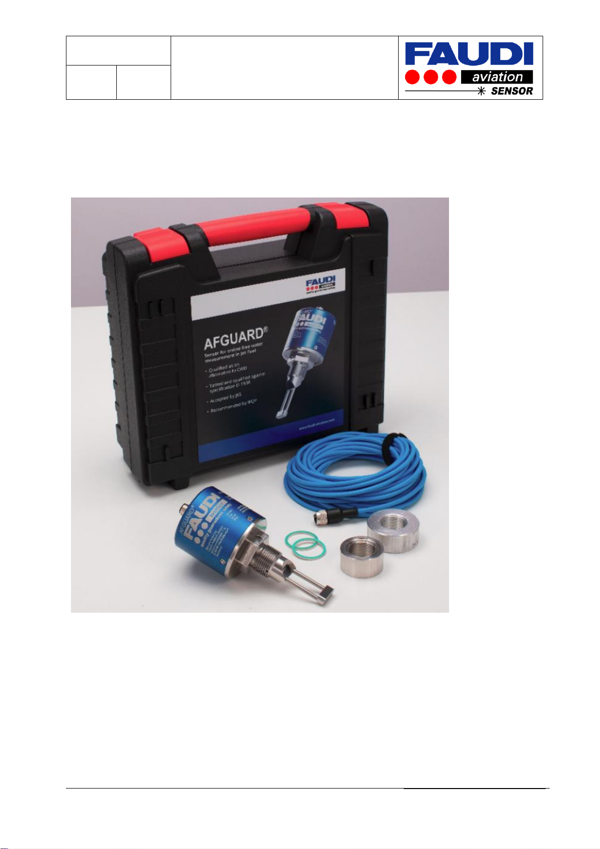
2.2 Scope of delivery
The following items are included in the delivery:
Transport case –Hard-Top-Case with foam
AFGUARD®with protective screw pipe to protect the mirror and optical path of the sensor
Set of accessories with the following content:
oSealing 2 mm and 1,5 mm thickness,
oAluminium or SS thread,
oBlue cable with Sensor plug connector 10 m length,
oOperating Instruction –behind the cover - foam
oCalibration protocol
If you have any questions, please ask your local supplier or distributor.
Version 2.2
Operating instructions
AFGUARD®
Zone 0/1 type
Page: 11
of: 47
FAUDI Aviation GmbH, Scharnhorststraße 7 B, D-35260 Stadtallendorf
BA_AFGUARD_Ex_rev2.2_Englisch
3 Installation and dismantling
3.1 Incoming acceptance, transport, storage
You should have received a delivery like shown in the picture below.
Make sure the packaging is undamaged!
Inform the supplier about damage to the packaging.
Keep the damaged packaging until the matter has been settled.
Make sure the contents are undamaged!
Inform the supplier about damage to the delivery contents. Keep the damaged products until
the matter has been settled.
Check that the scope of delivery is complete and agrees with your order and the shipping.
The packaging material used to store or to transport the product must provide shock
protection and humidity protection. The original packaging offers the best protection. Also,
keep to the approved ambient conditions (see "Technical data").
If you have any questions, please contact your supplier or your sales centre responsible.

Version 2.2
Operating instructions
AFGUARD®
Zone 0/1 type
Page: 12
of: 47
FAUDI Aviation GmbH, Scharnhorststraße 7 B, D-35260 Stadtallendorf
BA_AFGUARD_Ex_rev2.2_Englisch
3.2 Installation conditions
3.2.1 Dimensions
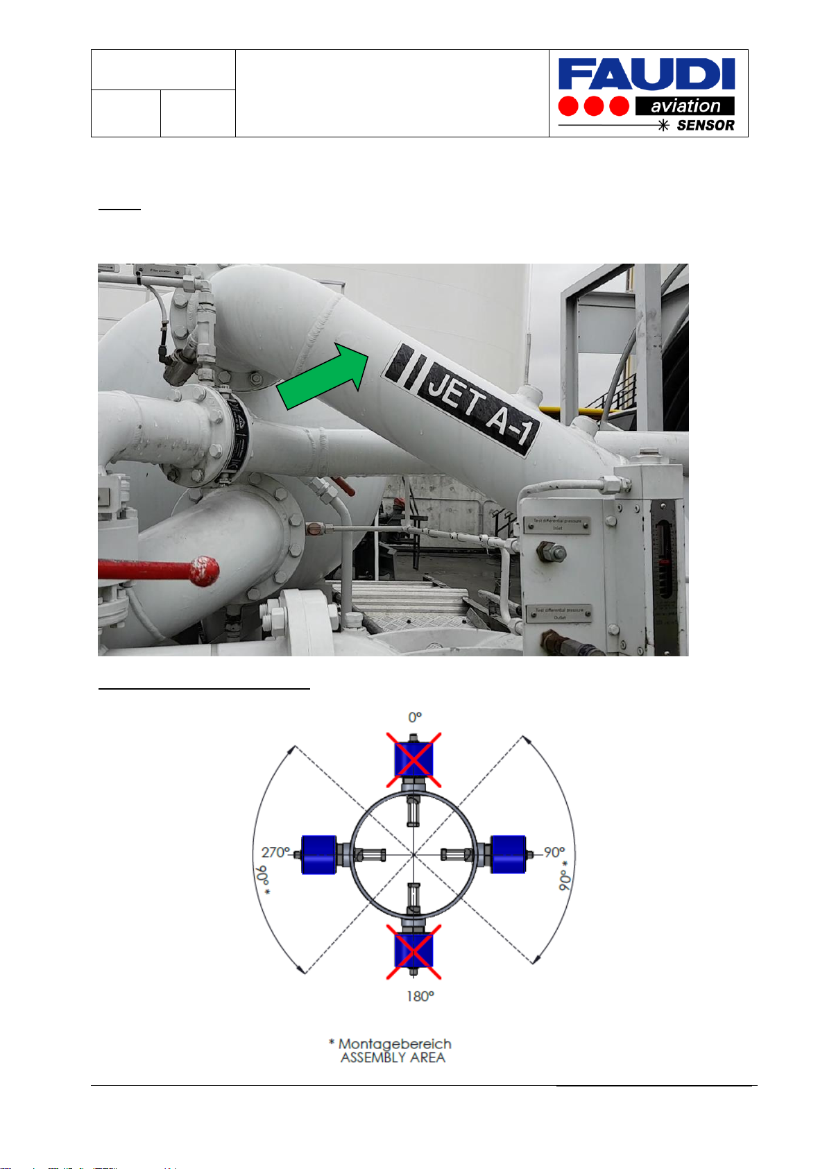
3.2.2 Mounting Position
The mounting position of the AFGUARD®should be horizontal. Other angles of inclination
are not permitted. Do not mount the AFGUARD®overhead. Make sure that there is enough
space inside the pipe to prevent
contact between the rear wall
and the mirror during
assembling –space for proper
installation.

Version 2.2
Operating instructions
AFGUARD®
Zone 0/1 type
Page: 13
of: 47
FAUDI Aviation GmbH, Scharnhorststraße 7 B, D-35260 Stadtallendorf
BA_AFGUARD_Ex_rev2.2_Englisch
Do not touch the optics or mirror to prevent damages.
3.3 Thread for AFGUARD installation
AFGUARD uses special threads to be weld into the pipe section. Threads are available in
Stainless steel and Aluminium.
Ensure to only use FAUDI-Aviation treads as they do have special design. Standard threads
do not work with AFGUARD.
Welding instruction is part of each thread delivery.
3.3.1 Installation place
Select the installation location so that there is easy access for later check and service work.
Make sure that the AFGUARD®and related assemblies are secured safely and vibration-
free.
Version 2.2
Operating instructions
AFGUARD®
Zone 0/1 type
Page: 14
of: 47
FAUDI Aviation GmbH, Scharnhorststraße 7 B, D-35260 Stadtallendorf
BA_AFGUARD_Ex_rev2.2_Englisch
3.3.2 Procedure for proper AFGUARD®installation
Step 1:
Select the best place for installation in the effluent pipe section.
Have a look on the assembly area:

Version 2.2
Operating instructions
AFGUARD®
Zone 0/1 type
Page: 15
of: 47
FAUDI Aviation GmbH, Scharnhorststraße 7 B, D-35260 Stadtallendorf
BA_AFGUARD_Ex_rev2.2_Englisch
Step 2:
Drain the pipe section.
Step 3:
Disconnect the pipe section from the vessel and clean the pipe section from flammable fluids.
Step 4:
Drill the hole for the AFGUARD® socket.
Drilling tools:
HSS cylindrical saw 45mm for a hand drilling
machine AFGUARD® socket stainless steel
FAUDI article number: 600355
HSS cylindrical saw 54mm for a hand drilling
machine AFGUARD® socket aluminium
FAUDI article number: 600356
Please have a look on the welding instruction.

Version 2.2
Operating instructions
AFGUARD®
Zone 0/1 type
Page: 16
of: 47
FAUDI Aviation GmbH, Scharnhorststraße 7 B, D-35260 Stadtallendorf
BA_AFGUARD_Ex_rev2.2_Englisch
Step 5:
Weld the special AFGUARD® socket into the pipe section.
Step 6:
After welding, it is recommended to thread the socket with a G3/4”-thread cutter.
Step 7:
Proceed a pressure test to ensure the required PN rating of the pipe section.
Step 8:
Reassemble the pipe section (ensure to use good working seals).
Version 2.2
Operating instructions
AFGUARD®
Zone 0/1 type
Page: 17
of: 47
FAUDI Aviation GmbH, Scharnhorststraße 7 B, D-35260 Stadtallendorf
BA_AFGUARD_Ex_rev2.2_Englisch
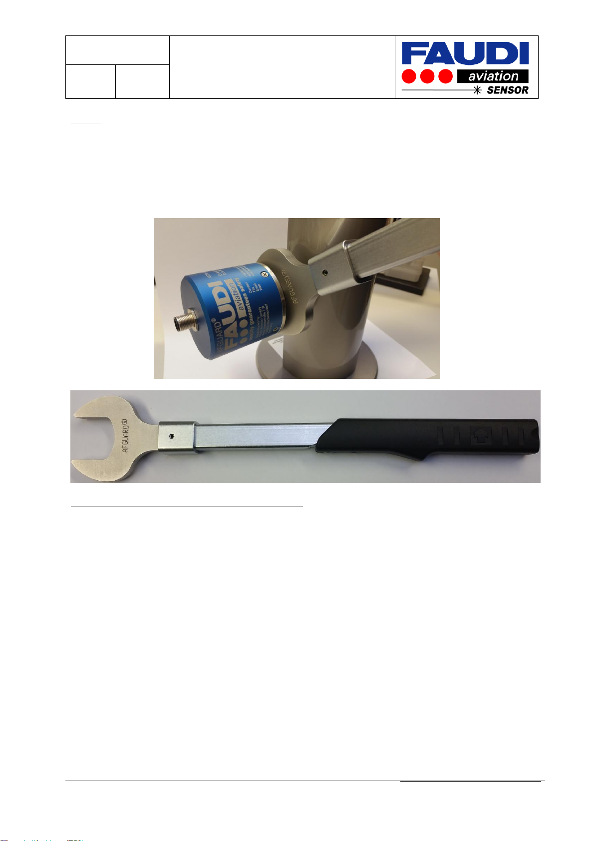
Step 9:
Install the AFGUARD® in the socket with one of the provided special KLINGERSIL-sealings. Start with
the 2 mm one and check the AFGUARD orientation in the pipe section. If not adequate –replace it by
the 1.5mm one.
Use the special AFGUARD® torque spanner to achieve the recommended torque of 50Nm.
Step 10: AFGUARD spanner FAUDI article no 600513
Connect the AFGUARD® to the control system of the truck / tank farm by the use of the blue two
wire cable.
For hazardous area use please ensure to only use an AFGUARD® together with a suitable barrier with
power supply.
Version 2.2
Operating instructions
AFGUARD®
Zone 0/1 type
Page: 18
of: 47
FAUDI Aviation GmbH, Scharnhorststraße 7 B, D-35260 Stadtallendorf
BA_AFGUARD_Ex_rev2.2_Englisch
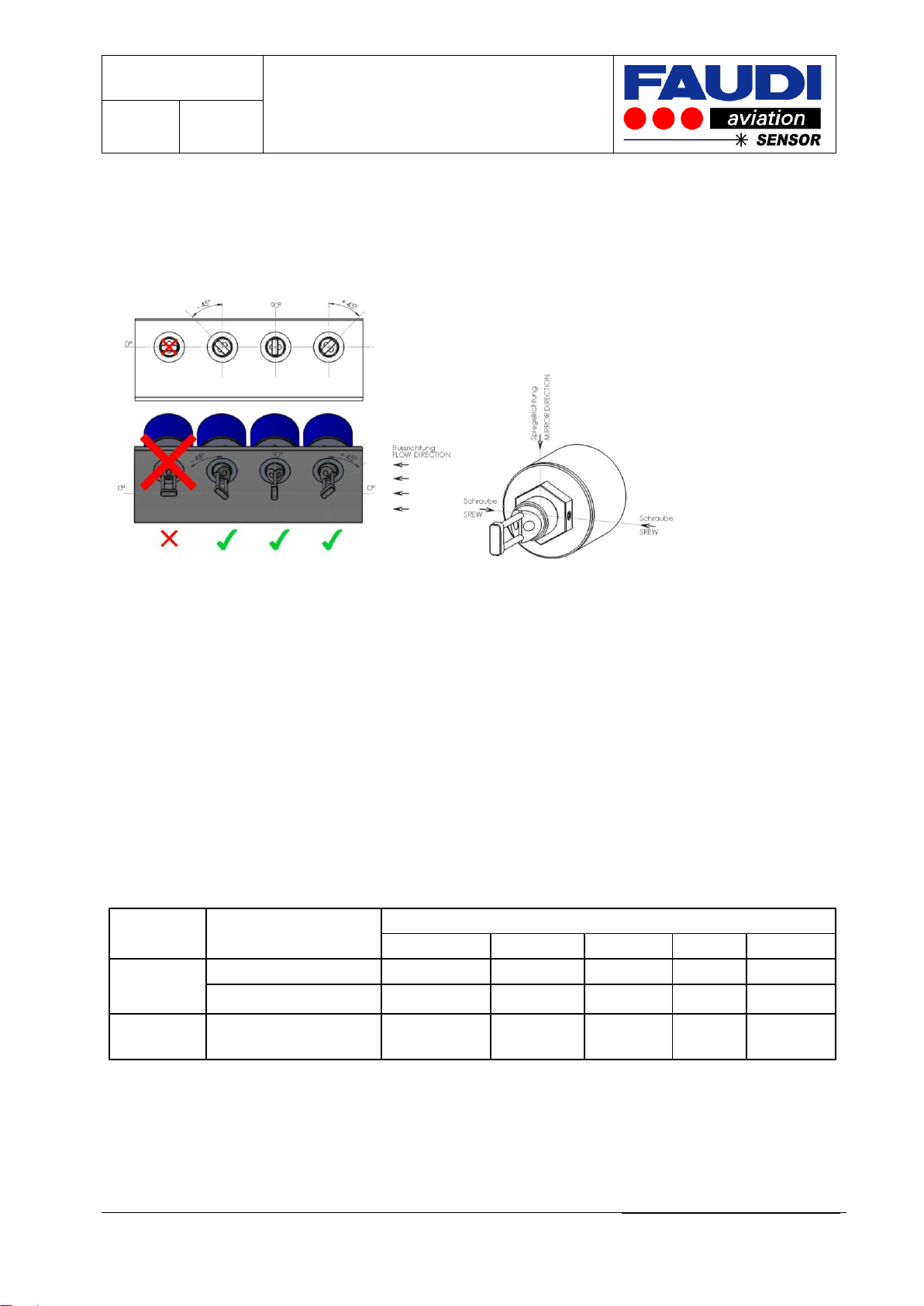
3.3.3 AFGUARD orientation in the pipe section
AFGUARD is capable in seeing different droplet size distributions. Especially for bigger
droplets AFGUARD orientation in the pipe section would be of importance.
Therefor we recommend installing the AFGUARD according the following picture
Orientation of AFGUARD could be achieved by the use of one of the supplied sealings. Start
with the 2 mm one to get an idea about the orientation of AFGUARD (by the use of
AFGUARD spanner) If insufficient change to the 1.5 mm sealing.
3.3.4 Measuring system
➢A complete measuring system comprises at least:
➢AFGUARD®
➢Sealing
➢Two wire cable connection with plug connector. It is only recommended to use the cable
delivered together with the AFGUARD®.
Isolating converter with transmitter supply.
E
3.3.4.1 Isolating converter with transmitter supply for signal output 4 to 20 mA (inherent safe)
Manufacturer
Type
Rating. EGB for Explosion group „IIB“
Uo
Io
Po
Co
Lo
Endress +
Hauser
RMA42
27,3 V
96,5 mA
659 mW
352 nF
100 mH
RN221N
(PTB 00 ATEX 2018)
27,3 V
87, 6 mA
597 mW
683 nF
18,9 mH
Phoenix
Contact
MACX MCR-EX-SL-RPSS-I
25,2 V
93 mA
587 mW
820 nF
4 mH
FAUDI Aviation highly recommends the use of isolating converters with transmitter supply.
Especially for use in hazardous area the use of inherent safe isolating converters is a must.
Protection class can be „ia“ or „ib“.
E
Version 2.2
Operating instructions
AFGUARD®
Zone 0/1 type
Page: 19
of: 47
FAUDI Aviation GmbH, Scharnhorststraße 7 B, D-35260 Stadtallendorf
BA_AFGUARD_Ex_rev2.2_Englisch
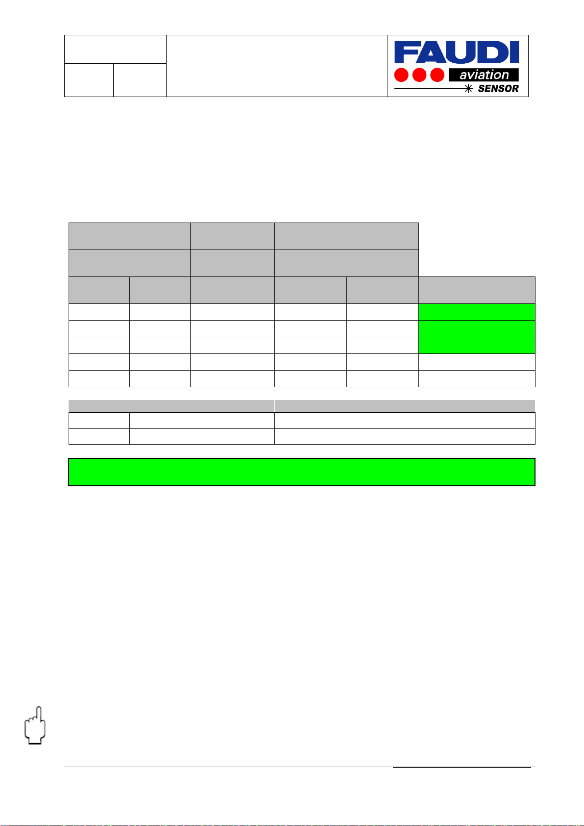
3.3.4.2 Proof of intrinsic safety for the interconnection of simple electrical circuitry Ex i
As the user of the AFGUARD free water sensor in combination with an isolating converter
with transmitter supply (sometimes together with other equipment like displays) it is evident
to make sure that your combination fits together. This should be done in front of installation.
If you are not sure on how to proceed –please call FAUDI Aviation Sensor GmbH.
Example: Combination of AFGUARD (Ex ia IIB) together with RN 221N (E+H)
Intrinsic safe AFGUARD
Proof of intrinsic
safety
Isolating converter with power
suply
AFGUARD Zone 0/1
Ex ia IIB
RN221N (E+H)
Ex ia IIB
Data
Data
Remarks
Ui
30 V
≥
U0
27,3
V
comply
Ii
100 mA
≥
I0
87,6
mA
comply
Pi
750 mW
≥
P0
597
mW
comply
Li+Lc
≤
L0
18,9
mH
Linegligible
Ci+Cc
≤
C0
683
nF
Cinegligible
cable data according EN 60079-14, 12.2.2.2
LC
1
µH/m
results in
18900
m
length of cable
CC
200
pF/m
results in
3415
m
length of cable
Use the result with shorter cable length
max. cable length
3415
m
acc. EN 60079-14
The calculation delivers the maximum length of cable (please use specific cable data) to be
used for the specified combination of AFUGARD, optional Display and isolating converter
with power supply.
3.3.5 Installing a measuring point
The AFGUARD®is an optical working measuring device that is designed for use in field
applications under rough conditions. Regarding these circumstances some minimum
directives have to be considered:
The optical path of the AFGUARD®(Glass rod, Mirror) is specially adjusted to the application.
Avoid direct contact with hard or sharp edges. Don’t touch with unprotected hand.
During installation of the AFGUARD® be careful applying force.
The recommended fastening force is 50 Nm –recommended to use AFGUARD spanner.
Handle the connection cable with care. Do not lay the cable under stress. Try to avoid sharp
angles.
Protect the cable against “getting caught“.
Please take care of possible electrostatic charges on the outer surface of the cable. It is
only allowed to clean the cable using wet cloth.
Version 2.2
Operating instructions
AFGUARD®
Zone 0/1 type
Page: 20
of: 47
FAUDI Aviation GmbH, Scharnhorststraße 7 B, D-35260 Stadtallendorf
BA_AFGUARD_Ex_rev2.2_Englisch
3.4 Installation examples
Try to touch the AFGUARD®only by the use of the housing to take it out of the box.
Remove the protection device of the optics
Put the sealing over the thread in front of the Sensor. Do not use other sealing than
recommended by FAUDI Aviation Sensor GmbH.
Screw the sensor into the fitting.
Pull it hand tight and apply the recommended torque setting of approx. 50 Nm.
Check the sealing
Adjust the cable. Take care not to stress the cable.
3.4.1 Measuring at the inlet and / or outlet of Filter Vessels
Filters are intended to be used as last filtering step in front of into plane filling. Its main task is
to filter out the residual parts of solids and the amount of free water in Jet fuel.
The water removing performance of the filters is measured based on the level of free water
detected by AFGUARD®sensors, placed at the vessel inlet and outlet. Free water will be
detected and, with these tools in place, the filters can be under constant surveillance to
insure their proper function. Maximum safety and constant surveillance of the system is
guaranteed even if filter elements indicate insufficient water removing capacity, especially
since the AFGUARD®will distinguish between water slug and Jet Fuel.
E
FAUDI Aviation highly recommends the use of isolating converters with transmitter
supply. Especially for use in hazardous area the use of inherent safe isolating
converters is a must. Protection classes „ia“ or „ib“ are allowed.
Connect the cable to the responding connecting terminals using one of the recommended
isolating converters with transmitter supply.
Finally connect the plug with the responding plug socket at the rear end of the AFGUARD®
Table of contents
Other Faudi Accessories manuals


