Faulhaber 3242 BX4 Series User manual
WE CREATE MOTION
Technical Manual
MCS 3242 BX4
MCS 3268 BX4
MCS 3274 BP4
EN

Imprint
2
Version:
4th edition, 26-08-2020
Copyright
by Dr. Fritz Faulhaber GmbH & Co. KG
Daimlerstr. 23 / 25 · 71101 Schönaich
All rights reserved, including those to the translation.
No part of this description may be duplicated, reproduced,
stored in an information system or processed or
transferred in any other form without prior express written
permission of Dr. Fritz Faulhaber GmbH & Co. KG.
This document has been prepared with care.
Dr. Fritz Faulhaber GmbH & Co. KG cannot accept any
liability for any errors in this document or for the
consequences of such errors. Equally, no liability can be
accepted for direct or consequential damages resulting
from improper use of the equipment.
The relevant regulations regarding safety engineering
and interference suppression as well as the requirements
specified in this document are to be noted and followed
when using the software.
Subject to change without notice.
The respective current version of this technical manual is
available on FAULHABER's internet site:
www.faulhaber.com
4th edition, 26-08-2020 7000.05058, 4th edition, 26-08-20207000.05058

4th edition, 26-08-2020 7000.05058, 4th edition, 26-08-20207000.05058
Content
3
1 About this document ....................................................................................................... 5
1.1 Validity of this document ...................................................................................... 5
1.2 Associated documents ............................................................................................ 5
1.3 Using this document .............................................................................................. 5
1.4 List of abbreviations ............................................................................................... 6
1.5 Symbols and designations ...................................................................................... 7
2 Safety ................................................................................................................................ 8
2.1 Intended use ........................................................................................................... 8
2.2 Safety instructions .................................................................................................. 8
2.3 Environmental conditions ...................................................................................... 9
2.4 EC directives on product safety ............................................................................. 9
3 Product description ........................................................................................................ 10
3.1 General product description ................................................................................ 10
3.2 Product information ............................................................................................. 11
3.3 Product variants .................................................................................................... 12
3.4 Cable outlet of the Motion Control System ....................................................... 13
3.4.1 Axial cable outlet (standard) ................................................................ 13
3.4.2 Radial cable outlet (option 5451) ........................................................ 13
3.4.3 Gearhead combination ......................................................................... 14
3.5 Connector overview ............................................................................................. 15
4 Installation ...................................................................................................................... 16
4.1 Mounting .............................................................................................................. 16
4.1.1 Mounting instructions .......................................................................... 16
4.1.2 Mounting on the front flange ............................................................. 17
4.1.3 Mounting with baseplate..................................................................... 19
4.2 Electrical connection ............................................................................................ 20
4.2.1 Notes on the electrical connection ...................................................... 20
4.2.2 Connecting the Motion Control System .............................................. 22
4.2.2.1 Power supply.......................................................................... 22
4.2.3 Connector pin assignment.................................................................... 23
4.2.4 I/O circuit diagrams ............................................................................... 25
4.2.5 External circuit diagrams ...................................................................... 26
4.3 Electromagnetic compatibility (EMC) .................................................................. 30
4.3.1 Considered systems ............................................................................... 30
4.3.2 Functional earthing .............................................................................. 32
4.3.3 Cable routing ........................................................................................ 33
4.3.4 Shielding................................................................................................ 34
4.3.4.1 Establishing the shield connection ....................................... 35
4.3.4.2 Establishing shield connection with cable lug ..................... 36
4.3.5 Using filters ........................................................................................... 37
4.3.5.1 Input-side filters..................................................................... 37
4.3.5.2 Insulation resistance .............................................................. 37
4.3.6 Error avoidance and troubleshooting ................................................. 38

4th edition, 26-08-2020 7000.05058, 4th edition, 26-08-20207000.05058
Content
4
5 Maintenance and diagnostics ........................................................................................ 39
5.1 Maintenance instructions .................................................................................... 39
5.2 Maintenance tasks ................................................................................................ 39
5.3 Diagnosis ............................................................................................................... 40
5.4 Troubleshooting ................................................................................................... 40
6 Accessories ...................................................................................................................... 41
7 Warranty ......................................................................................................................... 42

4th edition, 26-08-2020 7000.05058, 4th edition, 26-08-20207000.05058
About this document
5
1 About this document
1.1 Validity of this document
This document describes the installation and use of the following series:
MCS 3242 BX4
MCS 3268 BX4
MCS 3274 BP4
This document is intended for use by trained experts authorised to perform installation and
electrical connection of the product.
All data in this document relate to the standard versions of the series listed above. Changes
relating to customer-specific versions can be found in the corresponding data sheet.
1.2 Associated documents
For certain actions during commissioning and operation of FAULHABER products additional
information from the following manuals is useful:
These manuals can be downloaded in pdf format from the web page www.faulhaber.com/
manuals.
1.3 Using this document
Read the document carefully before undertaking configuration, in particular chapter
“Safety”.
Retain the document throughout the entire working life of the product.
Keep the document accessible to the operating and, if necessary, maintenance person-
nel at all times.
Pass the document on to any subsequent owner or user of the product.
Manual Description
Motion Manager 6 Operating instructions for FAULHABER Motion Manager PC software
Quick start guide Description of the first steps for commissioning and operation of FAULHABER Motion
Control Systems
Drive functions Description of the operating modes and functions of the drive
Accessories manual Description of the accessories

4th edition, 26-08-2020 7000.05058, 4th edition, 26-08-20207000.05058
About this document
6
1.4 List of abbreviations
Abbreviation Meaning
AC Alternating Current
AnIn Analogue input
AGND Analogue Ground
CAN Controller Area Network
CAN_L CAN-Low
CAN_H CAN-High
CS Chip Select
DC Direct Current
DigIn Digital input
DigOut Digital output
EFS Electronics Filter Supply
EGND Electronic Ground
EMC Electromagnetic compatibility
ESD Electrostatic discharge
ET EtherCAT (Ethernet for Control Automation Technology)
GND Ground
I/O Input/Output
PLC Programmable Logic Controller
PWM Pulse Width Modulation
RxD Receive Data
TTL Transistor Transistor Logic
TxD Transmit data

4th edition, 26-08-2020 7000.05058, 4th edition, 26-08-20207000.05058
About this document
7
1.5 Symbols and designations
CAUTION!
Hazards due to hot surfaces. Disregard may lead to burns.
Measures for avoidance
NOTICE!
Risk of damage.
Measures for avoidance
Pre-requirement for a requested action
1. First step for a requested action
Result of a step
2. Second step of a requested action
Result of an action
Request for a single-step action
Instructions for understanding or optimising the operational procedures

4th edition, 26-08-2020 7000.05058, 4th edition, 26-08-20207000.05058
Safety
8
2 Safety
2.1 Intended use
The Motion Control Systems described here consist of a combination of a base motor and
an integrated Motion Controller within a common housing with standard protection class
IP 54.
The Motion Control Systems are intended for use as slaves, and are particularly suitable for
positioning tasks in the following application fields:
Robotics
Toolbuilding
Automation technology
Industrial equipment and special machine building
Medical technology
Laboratory technology
When using the Motion Control Systems the following aspects should be observed:
Motion Control Systems contain electronic components and should be handled in
accordance with the ESD regulations.
Do not use the Motion Control Systems in environments where it will come into contact
with chemicals, nor in explosion hazard areas.
The Motion Control Systems should be operated only within the limits specified in the
corresponding data sheet.
Please ask the manufacturer for information about use under individual special
environmental conditions.
2.2 Safety instructions
NOTICE!
Electrostatic discharges can damage the electronics.
Wear conductive work clothes.
Wear an earthed wristband.
NOTICE!
Penetration of foreign objects can damage the electronics.
Do not open the housing.
NOTICE!
Inserting and withdrawing connectors whilst supply voltage is applied at the device can
damage the electronics.
Do not insert or withdraw connectors whilst supply voltage is applied at the device.

4th edition, 26-08-2020 7000.05058, 4th edition, 26-08-20207000.05058
Safety
9
2.3 Environmental conditions
Select the installation location so that clean dry air is available for cooling the Motion
Control System.
When installed within housings take particular care to ensure adequate cooling of the
Motion Control System.
Select a power supply that is within the defined tolerance range.
Protect the Motion Control System against chemical pollutants.
Motion Control Systems satisfy protection class IP54 acc. to DIN EN 60259.
2.4 EC directives on product safety
The following EC directives on product safety must be observed.
If the Motion Control Systems are being used outside the EU, international, national
and regional directives must be also observed.
Machinery Directive (2006/42/EC)
Because of their small size, no serious threats to life or physical condition can normally be
expected from electric miniature drives. Therefore the Machinery Directive does not apply
to our products. The products described here are not “incomplete machines”. Therefore
installation instructions are not normally issued by FAULHABER.
Low Voltage Directive (2014/35/EU)
The Low Voltage Directive applies for all electrical equipment with a nominal voltage of 75
to 1500 V DC and 50 to 1000 V AC. The products described in this technical manual do not
fall within the scope of this directive, since they are intended for lower voltages.
EMC Directive (2014/30/EU)
The directive concerning electromagnetic compatibility (EMC) applies to all electrical and
electronic devices, installations and systems sold to an end user. In addition, CE marking can
be undertaken for built-in components according to the EMC Directive. Conformity with
the directive is documented in the Declaration of Conformity.
Depending on the application, additional shaft seals may optionally be installed in the
base drive, which have to be maintained at regular intervals.
When combined with attachments (e.g., gearboxes) or for enhanced motor protection
an additional seal (O-ring) to enhance the protection class is optionally available (see
chap. 3.4.3, p. 14, chap. 4.1.2, p. 17 and chap. 5.2, p. 39).

4th edition, 26-08-2020 7000.05058, 4th edition, 26-08-20207000.05058
Product description
10
3 Product description
3.1 General product description
The FAULHABER Motion Control Systems described here are intended for controlled opera-
tion of various integrated base motors. They offer different functions and operating
modes, allowing complex drive tasks to be performed. Thanks to their compact design and
flexible connection options, the units can be used in a wide variety of applications and
require only basic wiring.
The Motion Control System can offer the following communication interfaces:
RS232
CANopen
RS232 and EtherCAT
Connections are also available for common or separate voltage supplies between motor
and controller, and also for a wide variety of inputs and outputs. Configuration of the
Motion Control System is performed using the FAULHABER Motion Manager V6.
The drives can be operated in the network via the CANopen or EtherCAT fieldbus interface.
In smaller setups, networking can also be performed via the RS232 interface. The Motion
Control Systems operate in the network in principle as a slave; master functionality for actu-
ating other axes is not provided. After basic commissioning via Motion Manager, the
Motion Control Systems can alternatively also be operated without communication inter-
face.
Motion Control Systems are normally secured using the tapped holes of the front panel.
Where cabling is connected axially, optionally the drive can be secured from below on a flat
base plate (see chap. 4.1, p. 16).
Analogue Hall sensors are used as feedback components.
Motion Control Systems with RS232, CANopen or EtherCAT interfaces can also be oper-
ated independently of the communication interface, if a function or a sequence pro-
gram has been programmed previously without digital command control.
4th edition, 26-08-2020 7000.05058, 4th edition, 26-08-20207000.05058
Product description
11
3.2 Product information
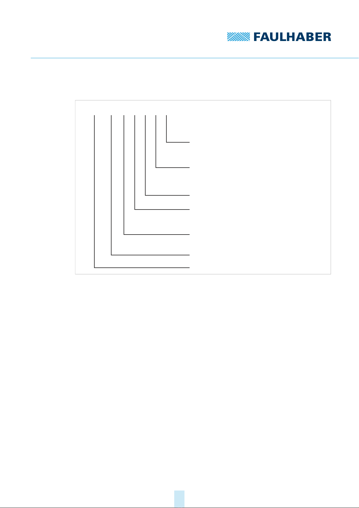
Fig. 1: Designation key
G...MCS 32 ... ... ...
BP4:
RS:
CO:
ET:
BX4:
G:
42:
68:
74:
32:
MCS:
024:
Serielle Schnittstelle RS 232
Schnittstelle CANopen
Schnittstelle EtherCAT
Motorfamilie (BL, 4-Pol-Technologie)
Wellendurchmesser 5 mm
Länge Vorbaumotor 42 mm
Länge Vorbaumotor 68 mm
Länge Vorbaumotor 74 mm
Durchmesser Vorbaumotor 32 mm
Motion Control System
Motornennspannung 24 V
Motorfamilie (BL, 4-Pol-Technologie)

4th edition, 26-08-2020 7000.05058, 4th edition, 26-08-20207000.05058
Product description
12
3.3 Product variants
The following product variants are possible:
Motion Control System with axial cable outlet
Motion Control System with radial cable outlet
In addition to the cable outlet, the following communication interfaces can be selected:
RS232
CANopen
RS232 and EtherCAT
The following motors are available for selection for each product variant:
3242 BX4
3268 BX4
3274 BP4
Depending on the motor, interface and cable outlet selected, the installed length and/
or height of the MCS will vary. Details can be found on the respective product data
sheet or in the relevant dimensional drawing.
Depending on the application, additional shaft seals may optionally be installed in the
base drive, which have to be maintained at regular intervals.
When combined with attachments (e.g., gearboxes) or for enhanced motor protection
an additional seal (O-ring) to enhance the protection class is optionally available (see
chap. 3.4.3, p. 14, chap. 4.1.2, p. 17 and chap. 5.2, p. 39).
4th edition, 26-08-2020 7000.05058, 4th edition, 26-08-20207000.05058
Product description
13
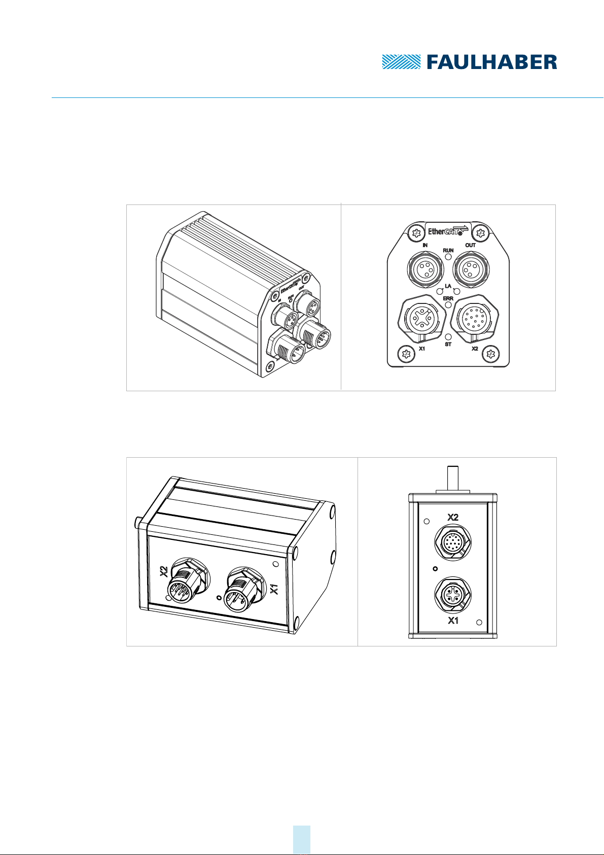
3.4 Cable outlet of the Motion Control System
3.4.1 Axial cable outlet (standard)
Fig. 2: Isometric view (left) and connector view (right) for axial cable outlet
3.4.2 Radial cable outlet (option 5451)
Fig. 3: Isometric view (left) and connector view (right) for radial cable outlet
4th edition, 26-08-2020 7000.05058, 4th edition, 26-08-20207000.05058
Product description
14
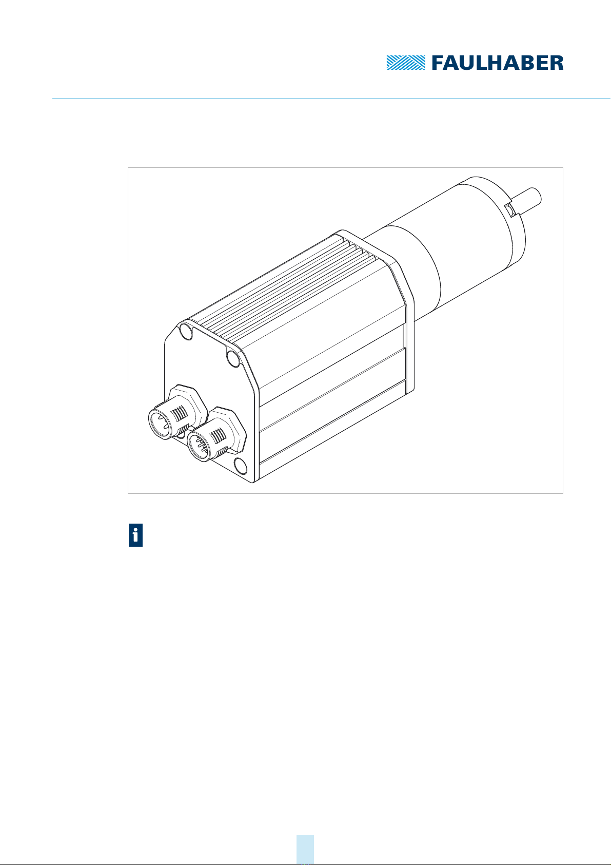
3.4.3 Gearhead combination
Fig. 4: Combination example with gearhead 32A
Using option 5657 and when the base drive is directly flange-mounted or in combina-
tion with attachments (e.g. gearboxes), an additional seal (O-ring), to enhance the pro-
tection class of the complete system, may be installed between the drive and the
attachment (see chap. 4.1.2, p. 17, and chap. 5.2, p. 39).

4th edition, 26-08-2020 7000.05058, 4th edition, 26-08-20207000.05058
Product description
15
Fig. 5: Front view of the motor flange A-side with radial groove (blue)
3.5 Connector overview
Tab. 1: Connector overview of the Motion Control System
Tab. 2: LED overview
Designation Function
IN/OUT Connection of the EtherCAT communication
X1 (supply) Power supply of the Motion Control System
X2 (I/O) Interface connection RS232/CAN and inputs or outputs for external circuits
Designation Interface Function
State LED all Green (continuous light): Device active.
Green (flashing): Device active. However the state machine has not yet reached
the Operation Enabled state.
Red (continuously flashing): The drive has switched to a fault state. The output
stage will be switched off or has already been switched off.
Red (error code): Booting has failed. Please contact FAULHABER Support.
RUN LED EtherCAT Green (continuous light): Connection present. Device is ready for use.
Green (flashing): Device is in the Pre-Operational. state
Green (single flash): Device is in the Safe-Operational. state
Off: Device is in the Initialisation state.
ERR LED EtherCAT Red (flashing): Faulty configuration.
Red (single flash): Local error.
Red (double flash): Watchdog timeout.
Off: No connection error
LA LED EtherCAT Green (continuous light): No data transfer. Connection to another participant
established.
Green (flashing): Data transfer active.
Off: No data transfer. No connection to another participant.

4th edition, 26-08-2020 7000.05058, 4th edition, 26-08-20207000.05058
Installation
16
4 Installation
Only trained experts and instructed persons with knowledge of the following fields may
install and commission the Motion Control System:
Automation technology
Standards and regulations (such as the EMC Directive)
Low Voltage Directive
Machinery Directive
VDE regulations (DIN VDE 0100)
Accident prevention regulations
This description must be carefully read and observed before commissioning.
Also comply with the supplementary instructions for installation (see chap. 2.3, p. 9).
4.1 Mounting
4.1.1 Mounting instructions
CAUTION!
The Motion Control System can become very hot during operation.
Place a guard against contact and warning notice in the immediate proximity of the
Motion Control System.
NOTICE!
Improper installation or installation using unsuitable attachment materials can damage the
Motion Control System.
Comply with the installation instructions.
NOTICE!
Installation and connection of the Motion Control System when the power supply is
applied can damage the Motion Control System.
During all aspects of installation and connection work on the Motion Control System,
switch off the power supply.
NOTICE!
Installation and connection of the Motion Control System on a surface that is not flat can
damage the Motion Control System.
Install the Motion Control System on a flat surface.
4th edition, 26-08-2020 7000.05058, 4th edition, 26-08-20207000.05058
Installation
17
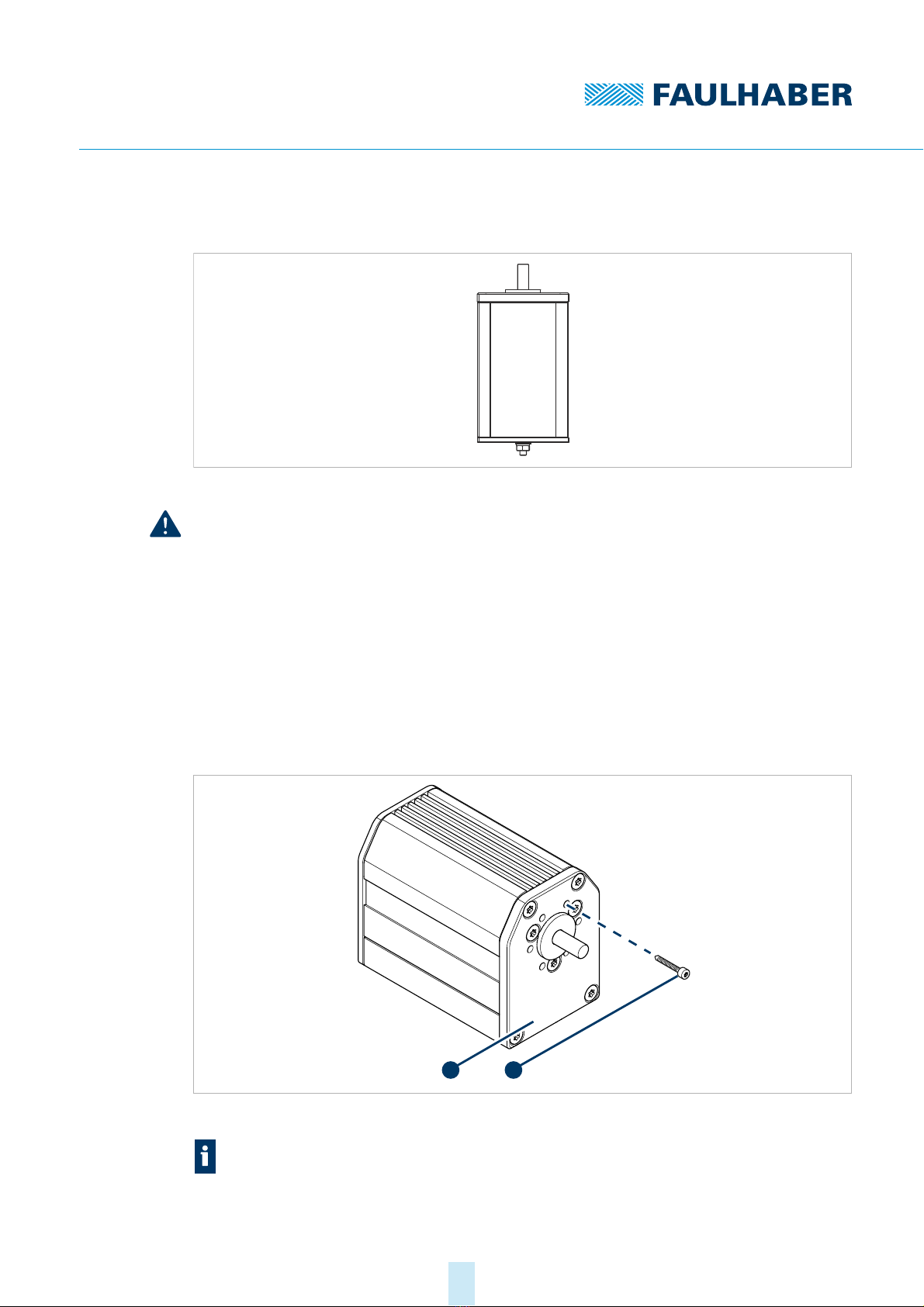
4.1.2 Mounting on the front flange
Fig. 6: V3 installation schematic diagram
NOTICE!
If the Motion Control System is installed with the shaft end facing upwards, liquids can
accumulate on the upward-facing surface and damage the device.
With V3 installation (see Fig. 6), make sure that no liquids can penetrate the bearings.
Optional: Use a Motion Control System with an additional shaft seal. Fitting a shaft seal
may reduce the motor performance (see chap. 4.1, p. 16)
Secure the Motion Control System (1) with screws (2) using the tapped bore holes on
the cover plate as shown in Fig. 7.
The maximum tightening torque of the screws is 130 Ncm.
The maximum screw-in depth is 4 mm.
Fig. 7: Mounting on the front flange
Using option 5657 and when the base drive is directly flange-mounted or in combina-
tion with attachments (e.g. gearboxes), an additional seal (O-ring), to enhance the pro-
tection class of the complete system, may be installed between the drive and the
attachment (see chap. 5.2, p. 39).
1 2
4th edition, 26-08-2020 7000.05058, 4th edition, 26-08-20207000.05058
Installation
18
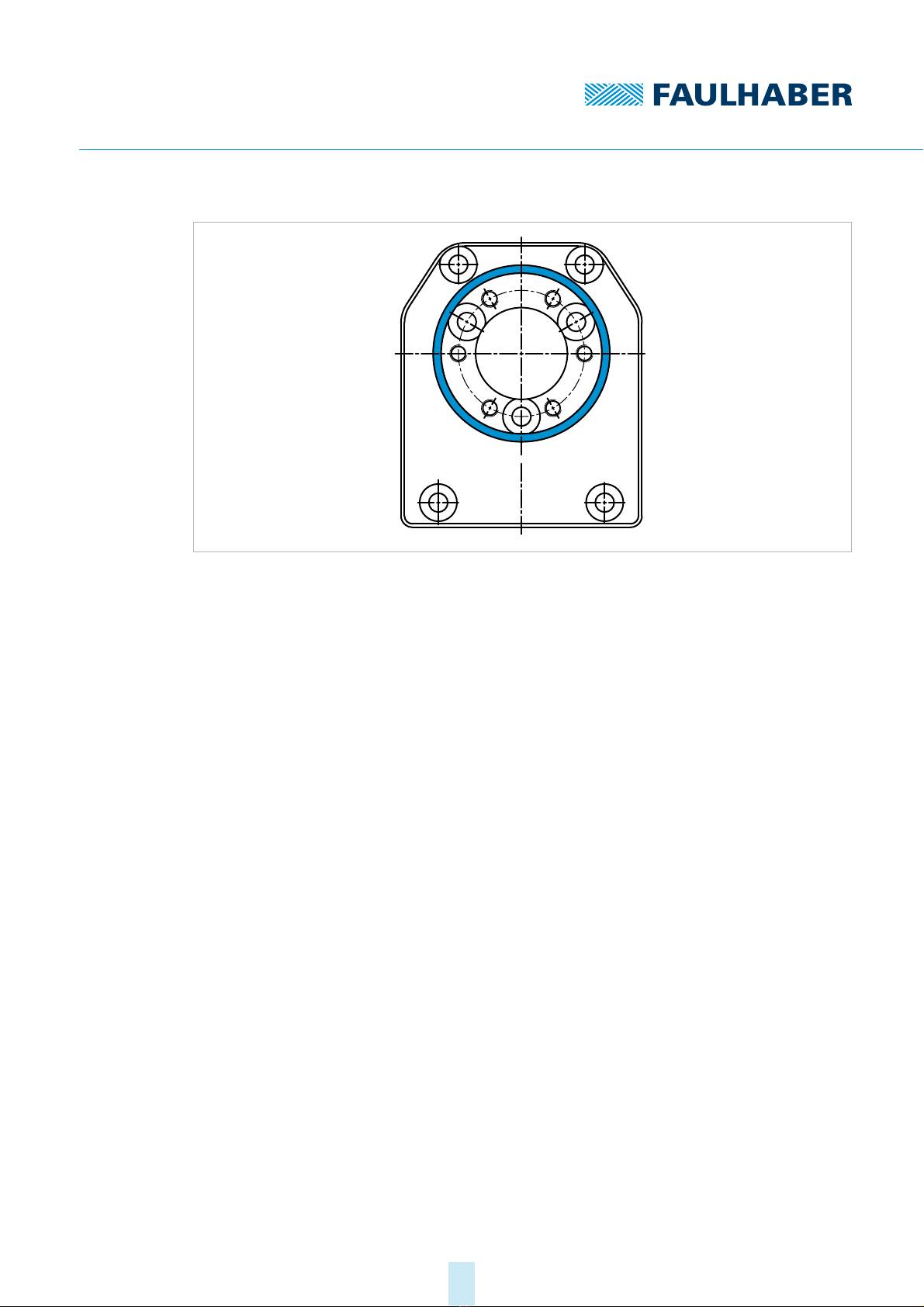
Fig. 8: Front view of the motor flange A-side with radial groove (blue)

4th edition, 26-08-2020 7000.05058, 4th edition, 26-08-20207000.05058
Installation
19
4.1.3 Mounting with baseplate
1. Secure the Motion Control System (1) with screws (3) to the base plate (2).
Screw type ST 2.2
The maximum tightening torque of the countersunk screws is 50 Ncm.
The maximum screw-in depth of the countersunk screws is 5 mm
Fig. 9: Mounting with baseplate
Screws and base plate are not part of the FAULHABER product portfolio and they must
be provided by the user.
Screw spacing 3274 BP4 RS/CO/ET 3268 BX4 RS/CO/ET 3242 BX4 RS/CO/ET
X 29 mm 29 mm 29 mm
Y103 mm 94 mm 68 mm
1
2
3
X
Y

4th edition, 26-08-2020 7000.05058, 4th edition, 26-08-20207000.05058
Installation
20
4.2 Electrical connection
4.2.1 Notes on the electrical connection
NOTICE!
Electrostatic discharges to the Motion Control Systems connections can damage the elec-
tronic components.
Observe the ESD protective measures.
NOTICE!
Incorrect connection of the wires can damage the electronic components.
Connect the wires as shown in the connection assignment.
NOTICE!
A short-term voltage peak during braking can damage the power supply or other con-
nected devices.
For applications with high load inertia, the FAULHABER Braking Chopper of the BC
5004 series can be used to limit overvoltages and thereby protect the power supply. For
more detailed information see the data sheet for the Braking Chopper.
The Motion Control Systems contain a PWM output stage for controlling the motors. Power
losses arising during operation and alternating electrical fields arising due to the pulsed
control of the motors, must be dissipated and damped by appropriate installation.
Connect the Motion Control System to an earthing system. This should be done prefera-
bly by mounting it on an earthed base plate, or alternatively by connecting it to an
earthed flange. Alternatively the earthing can be achieved by shielding the connecting
cables to the connection sockets.
Make sure that potential equalisation is present between all coupled parts of the sys-
tem.
If several electrical devices or controllers are networked by means of RS232 or CAN,
make sure that the potential difference between the earth potentials of the various
parts of the system is less than 2 V.
The EGND connection, and if necessary the shielding around the supply connection, are
available for potential equalisation.
Other manuals for 3242 BX4 Series
1
This manual suits for next models
7
Table of contents
Other Faulhaber Engine manuals


Popular Engine manuals by other brands


geos
geos LC 165 FS manual

Chris-Craft
Chris-Craft 350-Q Operator's manual

KEM
KEM KODIAK MARINE Operator's manual

Mercury
Mercury 200 Verado FourStroke Operation and maintenance manual

Briggs & Stratton
Briggs & Stratton 950 Series Advance Product Service Information

O.S. engine
O.S. engine MAX-50SX Owner's instruction manual


