Solo 2625 02i neo User manual

Type
2625 02i neo
Manual
KLEINMOTOREN GMBH
Stuttgarter Str. 41
D 71050 Sindelfingen, Germany
Edition 1 dated 16th April 2019
page 1 of 12 pages
Manual
for the
Engine SOLO type 2625 02i neo
Serial No.
Manufactured
Aircraft type
.....................................................................................
Registration
.....................................................................................
Owner
.....................................................................................
Log of revisions
No.
Edition date
revised page(s)
date of entry
1
16.04.2019
1 - 12

Type
2625 02i neo
Manual
KLEINMOTOREN GMBH
Stuttgarter Str. 41
D 71050 Sindelfingen, Germany
Edition 1 dated 16th April 2019
page 2 of 12 pages
Table of Content
page
Cover Page
1
Log of Revisions
1
Table of Content
2
1. General Engine Description
2
2. Technical Data
2
3. Operational Data and Limitations
3
4. Description of the ECU’s Functions
3
5. Installing Instructions and Tightening Torques
3
6. Operating Instructions
5
7. Maintenance Instructions
6
8. Engine Problems: Troubleshooting, CAN-Messages, Fault Memory
7
9. Wiring and Fuel Supply
9
10. Power Curve
12
1. General Engine Description
Twin - cylinder inline two - stroke engine
Liquid cooling
Lubrication by fuel-oil-mixture
Electronic fuel injection
Dual electronic high-voltage ignition
Crankshaft layout for belt transmission
Three-phase generator
2. Technical Data
Displacement
625 ccm bore 76 mm stroke 69 mm
Compression ratio
9,5 : 1
Ignition system
Dual electronic high-voltage ignition, mapped
Spark plugs
NGK B7HS, air gap at electrodes 0.7 mm
Fuel injection
Electronic, two throttle-valves, mapped
Sense of rotation
Clockwise in flight direction
Fuel
Premium unleaded gasoline, min. 95 RON , AVGAS100LL, or
mixtures of the two fuels
Lubrication
Fuel oil mixture 1:50 (2%), above a density altitude of 6000ft: mixture
1:30 (3.3%)
Oils according to the specification JASO FC or FD, recommended:
SOLO two stroke oil
Weight
24 kg without exhaust (aircraft manufacturer specific)
Alternator
12 V 500 W
Coolant
Antifreeze (Glysantin BASF G48) and tap water (0-20°dh) in a mixture
of 40:60 (27°C)

Type
2625 02i neo
Manual
KLEINMOTOREN GMBH
Stuttgarter Str. 41
D 71050 Sindelfingen, Germany
Edition 1 dated 16th April 2019
page 3 of 12 pages
3. Operational Data and Limitations
Takeoff
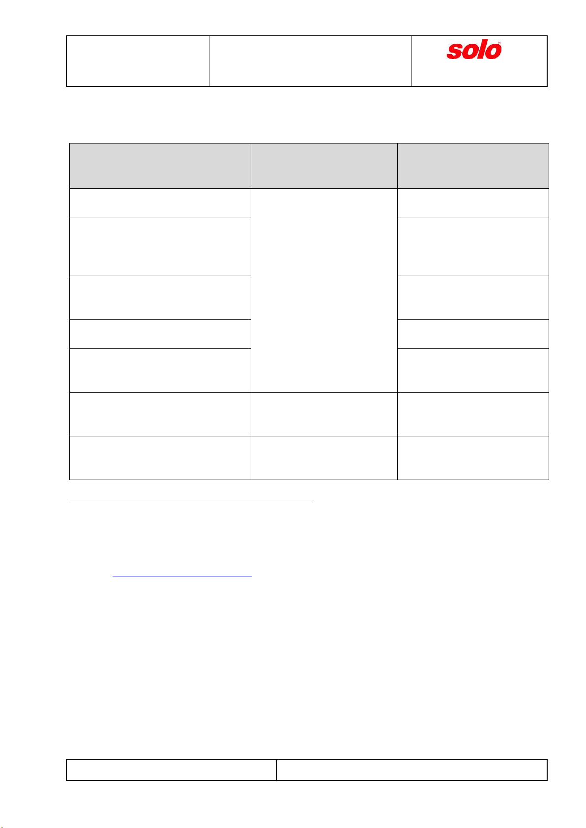
50 kW (68 hp) at a rotational speed of 6 600 rpm
Max. cont. power and
rotational speed
50 kW (68 hp) at 6 600 rpm
Max. rotational speed
6 700 rpm, limited by the ECU
Idle rotational speed
approx. 2 300 rpm
Max. coolant temp.
115 °C (240°F) measured in the cylinder head
Fuel consumption
approx. 24,5 l/h at max. continuous power
4. Description of the ECU’s Functions
Based on air pressure, air temperature, throttle position and engine speed, the ECU calculates
both the optimized injection quantity and the ignition timing.
For safety reasons, the engine control system is equipped with the following duplex-redundant
components: Engine speed sensor, throttle position sensor, injectors (channels A and B).
These parts are monitored by the ECU. By recognition of a fault, it switches automatically over
to the operative redundant component.
The external Fuel Pumps Electronics Unit allows the ECU to monitor the fuel pumps as well.
If an error is detected during engine operation, a code is sent to the engine monitoring device
via CAN and stored in the ECU’s fault memory.
5. Installing Instructions
The cylinders have to be nearly vertical with cylinder heads on top when the engine is in its
operating position.
The engine can be mounted at the drive side flange with 4 bolts M8. At the cylinder heads are
4 more threads M8 and at the bottom of the crankcase are 4 threads M10.
The load on the mounting threads may not exceed 5 kN each.
If the propeller is driven by a belt, the static belt tension may not be higher than 5 000 N
A water cooler with a cooling capability of 16 kW has to be used.
If an electric starter is used, its power has to be at least 400 W.
For the electrical wiring see the diagrams in chapter 9.
By using the regulator SOLO GR 30 according to the wiring diagram (see ch. 9) the power
supply of the engine components is redundant. Even if the battery fails the engine will continue
to run.
The ECU sends error codes via CAN if errors occur (see ch. 8.2). SOLO supplies the CAN
protocol on demand.

Type
2625 02i neo
Manual
KLEINMOTOREN GMBH
Stuttgarter Str. 41
D 71050 Sindelfingen, Germany
Edition 1 dated 16th April 2019
page 4 of 12 pages
fuel system:
oSolo recommends to use the optional Fuel Supply Unit (BVE). It contains two pumps, the
corresponding check-valves, the pressure regulator and a fine mesh filter. Instructions for
installing the BVE:
Installation below the main tank, pumps horizontally and at the bottom.
The fuel line coming from the tank must be short and rising towards the fuel tank.
Dirt must be prevented from entering the main tank. Therefore, Solo recommends to
use a tank inlet filter with a 10 micron mesh.
The pressure loss via the connection line to the engine (including fuel valve and fittings)
may not exceed 50 mbar at a flow rate of 30 lph
oIf other fuel pumps are intended to be used, please contact Solo in advance and ask
whether they are suitable. Especially pay attention to the following:
The fuel pressure in the fuel distributor of the throttle valve unit may not drop below
2,85 bar or rise above 3,1 bar during engine operation.
The injection valves must be protected by a 10 micron fine mesh filter.
If the current consumption is > 2A per pump, a larger smoothing capacitor may be
required. (see page 10, Wiring Power Supply)
oAll fuel lines have to be protected against fire. Solo recommends Goodrich 811 fuel lines,
size dash 04.

Type
2625 02i neo
Manual
KLEINMOTOREN GMBH
Stuttgarter Str. 41
D 71050 Sindelfingen, Germany
Edition 1 dated 16th April 2019
page 5 of 12 pages
Table of Torques
Spark plug 20 Nm
Drive pulley on crankshaft 100 Nm
Bolts and nuts M 6 12 Nm
Bolts and nuts M 8 20 Nm
Bolts and nuts M 10 40 Nm
Alternator rotor on crankshaft 80 Nm
Annotation: All tightening torques specified here are nominal values. The display deviation of the
torque tools used must not exceed ± 5%.
6. Operating Instructions
A basic requirement for the safe operation of the engine is compliance with the following
instructions:
Check before startup:
Check the fuel quantity in the tank.
Check throttle lever for free movement.
Check outside of engine, engine compartment, belt transmission
and mountings for proper condition. Pay attention to leaks.
Ignition: „OFF". Turn the propeller several times by hand to
check for abnormal noise or hard motion of the engine.
Check the coolant level.
Check the error memory of the engine monitoring instrument.
Startup:
Throttle lever idle.
Open fuel cut-off valve.
Main switch „ON“.
Ignition "ON".
Check for safety space around the propeller. Engage the wheel
brake.
Start the engine.
Check before takeoff:
Check the engine monitoring instrument for new error messages.
Conduct an ignition check at idle (2.300 RPM).
Maximum engine speed drop: 200 RPM.
Takeoff and climb:
Accelerate to full throttle because the injectors are monitored at
full throttle only.
Limits of rotational speed and temperatures may not bee
exceeded.
Stopping the engine:
Switch off ignition. Further procedure according to aircraft manual.
Startup during flight:
Throttle lever idle.
Open the fuel cut-off valve.
Main switch „ON“.
Extend engine / propeller into flight position and disengage the
propeller stop (according to the Aircraft’s flight manual.)
Ignition “ON”.
Push starter button until engine runs.
Throttle into full.

Type
2625 02i neo
Manual
KLEINMOTOREN GMBH
Stuttgarter Str. 41
D 71050 Sindelfingen, Germany
Edition 1 dated 16th April 2019
page 6 of 12 pages
7. Maintenance Instructions
In addition to the daily checks before startup and before takeoff, the following inspection and
maintenance work is mandatory:
Check every 25 hours or
once a year (whatever is
reached first)
General, thorough visual inspection: pay attention to loose or
missing parts and leaks.
Check spark plugs.
Clean engine and air filter(s).
Put grease on the starter gearing.
Check all accessible screws and nuts for correct tightening
torque.
Check all bowden cables and mechanical controls.
Check cables and electrical connections, especially the ECU
power supply. To do this, temporarily pull the ECU fuse 1 and
check if the ECU is still supplied with power. Repeat the
same for the ECU fuse 2.
Turn the engine system’s main switch temporarily off during
a test run. The engine must continue running.
Every 100 hours
Exchange the fuel filter integrated in the Solo Fuel Supply Unit.
Every 400 hours
Engine inspection and overhaul by Solo.
We strongly recommend a detailed check of the whole
engine system wiring, including connectors.
Conservation and storage
of the engine.
If the engine is not used for more than 2 months, preserve and
store it as follows:
Inject approx. 2.5 ml of two stroke oil into each throttle body and
crank the engine 10 turns by hand. Cover intake openings.

Type
2625 02i neo
Manual
KLEINMOTOREN GMBH
Stuttgarter Str. 41
D 71050 Sindelfingen, Germany
Edition 1 dated 16th April 2019
page 7 of 12 pages
8. Engine Problems
8.1 Troubleshooting
The engine doesn’t start
1. Check battery voltage.
2. Check whether enough fuel is in the tank.
3. Check the ECU’s power supply.
4. Ignition switch „OFF“! Turn the propeller by hand and check the engine’s compression.
5. Check the electric starter. Does it turn the engine fast enough?
6. Check whether the engine is flooded with fuel. If so, pull the fuel pump fuses and try to start
the engine with throttle half open, until you hear the first ignitions. Engage the fuel pump fuses
again and start the engine.
The engine gets (too) hot
Warning! Overheating can cause severe damages! Shut off the engine as soon as possible!
Check cooling system. Is the coolant level sufficient? Does the coolant pump work? Are any hoses
squeezed? Is the radiator clogged?
The engine doesn’t reach its nominal power or the rotational speed drops during operation
During flight, push –if possible –the throttle lever to full. (Only then the injectors are
automatically monitored) If this doesn’t help, stop the engine as soon as possible!
On the ground:
1. Check, whether the throttle valves open completely.
2. Ignition switch „OFF“! Turn the propeller by hand and check the engine’s compression.
3. Conduct an ignition check at idle (2.300 RPM). Maximum engine speed drop: 200 RPM.
4. If not already done: Run the engine at least for 30 seconds with full throttle. Check the error
memory of the engine monitoring instrument.
5. Clean or replace the air filter(s).
The alternator LED lights up, while the engine is running
Alternator or regulator are not working properly. Watch the Battery voltage!

Type
2625 02i neo
Manual
KLEINMOTOREN GMBH
Stuttgarter Str. 41
D 71050 Sindelfingen, Germany
Edition 1 dated 16th April 2019
page 8 of 12 pages
8.2 CAN-Messages:
The ECU sends the following messages via the CAN bus:
CAN message
Cases in which a fault
report is considered
irrelevant:
recommended reaction in
case of an error during flight:
TPS faulty (both channels)
Sensor faults are usually
not critical, if they occur
only rarely and for a few
miliseconds. No reaction is
required then. (Especially
the occurance of speed
sensor errors during
starting or stopping the
engine is normal.)
Push the throttle lever to full
or stop the engine.
engine temperature sensor faulty
No indication of engine
temperature! It won’t be
noticed if the engine
overheats.
internal air pressure sensor faulty/
air temperature sensor faulty
At low air density, the
performance of the engine is
weaker than normal.
TPS channel 1 faulty /
TPS channel 2 faulty
No immediate action
required.
speed sensor channel 1 faulty /
speed sensor channel 2 faulty
The engine has an increased
probability of failure. Fly
carefully.
injection channel A defective /
injection channel B defective
---
The engine has an increased
probability of failure. Fly
carefully.
fuel pump 1 faulty /
fuel pump 2 faulty
The tank is (almost) empty.
The engine has an increased
probability of failure. Fly
carefully.
Defects have to be corrected before the next flight.
8.3 Fault memory
The ECU stores all errors which are detected during engine operation in its internal fault memory.
For reading this, the software WinTrijekt NEO is required. It can be downloaded from the Solo
website: https://aircraft.solo.global/gb/.

Type
2625 02i neo
Manual
KLEINMOTOREN GMBH
Stuttgarter Str. 41
D 71050 Sindelfingen, Germany
Edition 1 dated 16th April 2019
page 9 of 12 pages
-
+
-
+
-
+
-
+
Fuse 2 ECU
4A M
Fuse IC 2
5A M
CAN
Fuse FP 2
5A M
-
+
-
+
Fuse FP 1
5A M
Fuel Pumps Electronics Unit
Main Connector
(TE 929504-4)
1
4
6
2
10
8
Signal Connector
(Deutsch DTM06-6S)
1
2
24
25
26
27
Fuse 1 ECU
4A M
6
L
H
5A M
IC 1
IC 2
1
2
3
4
5
Fuse IC 1
speed sensor
(Deutsch DTM04-6P
connector)
3
4
5
6
2
3
4
Main Connector
(TE 929504-4)
Power Connector
(Deutsch DTM06-
4S)
ECU
18
19
20
21
22
23
30
31
32
33
34
28
29
14
15
16
17
1
Fuel Pumps Electronics Unit
ignition switch 2
ignition switch 1
TXD
RXD
IV
IV
8
9
10
11
12
13
2
3
4
5
6
7
3
5
7
9
1
28
3
2
5
RS 232
5
6
TPS
(Deutsch DTM04-6P
connector)
4
Cylinder 1
(rear)
Channel A
Cylinder 2
(front)
Channel A
Cylinder 1
(rear)
Channel B
Cylinder 2
(front)
Channel B
IV
IV
1
2
3
0,35 mm2/ 22 AWG
13
Current Signal P2
21
IV Cyl. 2, Channel A
2
Power GND
12
Signal TPS channel 2
20
IV Cyl. 1, Channel A
31
CAN H
4
Fuel Pump P2
14
RS 232 RXD
22
IV Cyl. 1, Channel B
30
CAN L
distributor rail +12V engine system
distributor rail power GND engine system
solo
Vertriebs- und
Entwicklungs- GmbH
Engine Control System
2625 01i neo and 2625 02i neo
10
Engine Temperature
17
Power GND
26
Signal GND 2
34
Ignition Coil 2
9
Current signal P1
16
Signal GND 1
25
Fuel Pump P1
04.01.2020
8
Signal TPS channel 1
15
RS 232 TXD
23
0,5 mm2/ 20 AWG
1,0 mm2/ 17 AWG / 18 AWG
recommended cable sizes: (according to DIN VDE 0295: underlined, US-Standard: printed in italics)
1,5 mm2/ 16 AWG (1,5 mm2is not suitable for the ECU connector)
32
+5V
ambient air
temperature
sensor
Speed Channel 2
29
Speed Channel 1
Annotations:
• All junctions need to be protected of vibrations in an adequate way.
• If the fuel pumps differ from those used in the Solo Fuel Supply Unit, the fuses FP1 and FP2 and the supply cable sizes might have to be changed. (fuses max. 7,5A M)
• For the engine environment, Solo recommends to use finest stranded, heat-resistantcables. (e.g. SiFF)
• The Solo Fuel Pumps Electronics Unit is both available with one main PCB connector and with two separate wired connectors (signal and power connector).
ECU(Trijekt bee) - Pinout
1
Power GND
11
Ambient Air Temp.
18
Ignition Coil 1
27
+ 12V
3
+ 12V
engine temp.
sensor
(Bosch 1 928 403 874
connector)
IV Cyl. 2, Channel B
9. Wiring and Fuel Supply Wiring ECU

Type
2625 02i neo
Manual
KLEINMOTOREN GMBH
Stuttgarter Str. 41
D 71050 Sindelfingen, Germany
Edition 1 dated 16th April 2019
page 10 of 12 pages
Wiring Power Supply Connectors of the Fuel Pumps
Electronics Unit
a) with Signal and Power Supply
Connector
b) with Main Connector
solo
Vertriebs- und
Entwicklungs- GmbH
Power Supply
2625 01i neo and 2625 02i neo
15.11.2019
Battery
Voltage: 12V resp. 13,2V
Lead (AGM) or LiFePo4
CAUTION!
max. charging current ≥ 30A
-
-
Annotations:
• The regulator shouldnt't be mounted directly to the engine or the pylon.
4
4
Phase 3
3
3
Phase 1
DELPHI Metri-Pack 480 connector
1
DTM
06-4S
1
2
2
Phase 2
2
2
DTM
04-4P
1
1
1534
4628
1213
1592
+
2
2
80A T
40A M
0,2A M
+
Starter
capacitor 47mF, 40V
EPCOS B41458B7479M000
470 Ω, 1W
DEUTSCH connector
Charge Out
REGULATOR
GR30
charging light
DEUTSCH connector
battery fuse
main switch
alternator fuse
1
DTP
06-2S
DTP
04-2P
1
+ Supply
distributor rail +12V
engine system
GEN
OVP
distributor rail power
GND engine system
Engine turn
3
3
6 mm2/ 9 AWG / 10 AWG
10 mm2/ 6 AWG / 7 AWG
recommended cable sizes: (according to DIN VDE 0295: underlined, US-Standard: printed in italics)
GND
0,5 mm2/ 20 AWG
2,5 mm2/ 14 AWG
4 mm2/ 10 AWG /11 AWG
ALTERNATOR
3-phase, 500W
pump 1
pump 2
3
4
Fuel Pump
Electronics Unit
-
+
+
-
signal connector
(Deutsch DTM04-6P)
power supply
connector
(Deutsch
DTM04-4P)
1
2
3
4
5
6
1
2
9
2
6
10
Fuel Pump Electronics Unit
7
8
1
3
5
4
Main Connector (TE 963357-4)
-
+
+
pump 1
pump 2
-

Type
2625 02i neo
Manual
KLEINMOTOREN GMBH
Stuttgarter Str. 41
D 71050 Sindelfingen, Germany
Edition 1 dated 16th April 2019
page 11 of 12 pages
Fuel Supply
The following schematic shows the fuel system with the Solo Fuel Supply Unit (BVE) being used,
but without the required tank inlet filter(s). If other pumps are installed, there may be deviations.
These are within the aircraft manufacturer’s area of responsibility then.
shut-off valve
pump 1
pump 2
fuel tank
(main tank)
pressure
regulator
included in fuel-supply-unit
fine mesh
filter
included in throttle-body-unit
IV
IV
IV
Cyl. 1 (rear)
Channel A
Cyl. 1 (rear)
Channel B
Cyl. 2 (front)
Channel A
Cyl. 2 (front)
Channel B
IV

Type
2625 02i neo
Manual
KLEINMOTOREN GMBH
Stuttgarter Str. 41
D 71050 Sindelfingen, Germany
Edition 1 dated 16th April 2019
page 12 of 12 pages
10. Power curve
20,00
25,00
30,00
35,00
40,00
45,00
50,00
55,00
4000 4500 5000 5500 6000 6500 7000
Engine speed (RPM)
Power (kW)
Table of contents
Other Solo Engine manuals
Popular Engine manuals by other brands

Eaton
Eaton Crouse-hinds series operating instructions

Engine distributors
Engine distributors LSG 635 Operator's handbook

O.S. engine
O.S. engine MAX-12CV-R Owner's instruction manual

Volvo Penta
Volvo Penta TWD1672GE manual

ZF
ZF 400 Family operating instructions

BRP
BRP Rotax 912 i Series Maintenance manual