Faulhaber 22 BX4 SC Series User manual

WE CREATE MOTION
Technical Manual
22xx...BX4(S) SC
32xx...BX4 SC
32xx...BX4 SCDC
26xx...B SC
1525...BRC
1935...BRC
3153...BRC
2214...BXT H SC
3216...BXT H SC
4221...BXT H SC
EN

Imprint
2
Version:
2nd edition, 31-03-2020
Copyright
by Dr. Fritz Faulhaber GmbH & Co. KG
Daimlerstr. 23 / 25 · 71101 Schönaich
All rights reserved, including those to the translation.
No part of this description may be duplicated, reproduced,
stored in an information system or processed or
transferred in any other form without prior express written
permission of Dr. Fritz Faulhaber GmbH & Co. KG.
This document has been prepared with care.
Dr. Fritz Faulhaber GmbH & Co. KG cannot accept any
liability for any errors in this document or for the
consequences of such errors. Equally, no liability can be
accepted for direct or consequential damages resulting
from improper use of the equipment.
The relevant regulations regarding safety engineering
and interference suppression as well as the requirements
specified in this document are to be noted and followed
when using the software.
Subject to change without notice.
The respective current version of this technical manual is
available on FAULHABER's internet site:
www.faulhaber.com
2nd edition, 31-03-2020 7000.05061, 2nd edition, 31-03-20207000.05061

2nd edition, 31-03-2020 7000.05061, 2nd edition, 31-03-20207000.05061
Content
3
1 About this document ....................................................................................................... 5
1.1 Validity of this document ...................................................................................... 5
1.2 Associated documents ............................................................................................ 5
1.3 Using this document .............................................................................................. 5
1.4 List of abbreviations ............................................................................................... 6
1.5 Symbols and designations ...................................................................................... 6
2 Safety ................................................................................................................................ 7
2.1 Intended use ........................................................................................................... 7
2.2 Safety instructions .................................................................................................. 7
2.3 Environmental conditions ...................................................................................... 8
2.4 EC directives on product safety ............................................................................. 8
3 Product description .......................................................................................................... 9
3.1 General product description .................................................................................. 9
3.2 Product information ............................................................................................. 10
3.3 Product variants .................................................................................................... 12
4 Installation ...................................................................................................................... 14
4.1 Mounting .............................................................................................................. 14
4.1.1 Mounting instructions .......................................................................... 14
4.1.2 Mounting the motor............................................................................. 15
4.2 Electrical connection ............................................................................................ 16
4.2.1 Notes on the electrical connection ...................................................... 16
4.2.2 Electrical connection of motor............................................................. 18
4.2.2.1 EMC-compliant installation................................................... 18
4.2.2.2 EMC suppressor circuit........................................................... 18
4.2.2.3 Pin assignment ....................................................................... 19
4.2.2.4 Connection examples ............................................................ 22
5 Description of functions ................................................................................................ 24
5.1 Operating modes .................................................................................................. 24
5.1.1 Speed-controlled operation ................................................................. 24
5.1.1.1 BL motors with digital Hall sensors ...................................... 24
5.1.1.2 BL motors with analogue Hall sensors ................................. 25
5.1.1.3 BL motors without Hall sensors (BRC motors)...................... 27
5.1.2 Operation as voltage controller........................................................... 28
5.2 Set-point specification ......................................................................................... 28
5.2.1 Fixed speed specification...................................................................... 28
5.2.2 Analogue set value specification ......................................................... 29
5.2.3 PWM set value specification................................................................. 30
5.3 Configuration of the digital output .................................................................... 31
5.4 Parameter settings ............................................................................................... 32
5.4.1 Current limitation values...................................................................... 32
5.4.2 Fixed speed............................................................................................ 33
5.4.3 Lines per motor revolution................................................................... 33
5.4.4 Maximum speed.................................................................................... 34
5.4.5 Controller parameters .......................................................................... 35
5.4.6 Start time (in sensorless mode only) .................................................... 35

2nd edition, 31-03-2020 7000.05061, 2nd edition, 31-03-20207000.05061
Content
4
5.4.7 Minimum speed (in sensorless mode only).......................................... 35
5.4.8 Delayed Current Error (only error output) .......................................... 35
5.5 Protective functions ............................................................................................. 36
5.5.1 I2t current limitation............................................................................. 36
5.5.2 Overtemperature shutdown ................................................................ 37
5.6 Voltage output at motor ..................................................................................... 37
6 Commissioning ............................................................................................................... 38
7 Maintenance ...................................................................................................................40
7.1 Maintenance tasks ................................................................................................ 40
7.2 Troubleshooting ................................................................................................... 40
8 Accessories ...................................................................................................................... 41
9 Warranty ......................................................................................................................... 42

2nd edition, 31-03-2020 7000.05061, 2nd edition, 31-03-20207000.05061
About this document
5
1 About this document
1.1 Validity of this document
This document describes the installation and use of the following series:
This document is intended for use by trained experts authorised to perform installation and
electrical connection of the product.
All data in this document relate to the standard versions of the series listed above. Changes
relating to customer-specific versions can be found in the corresponding data sheet.
1.2 Associated documents
For certain actions during commissioning and operation of FAULHABER products additional
information from the following manuals is useful:
1.3 Using this document
Read the document carefully before undertaking configuration, in particular chapter
“Safety”.
Retain the document throughout the entire working life of the product.
Keep the document accessible to the operating and, if necessary, maintenance person-
nel at all times.
Pass the document on to any subsequent owner or user of the product.
22xx...BX4(S) SC
32xx...BX4 SC
32xx...BX4 SCDC
26xx...B SC
1525...BRC
1935...BRC
3153...BRC
2214...BXT H SC
3216...BXT H SC
4221...BXT H SC
Manual Description
Motion Manager 6 Operating instructions for FAULHABER Motion Manager PC software

2nd edition, 31-03-2020 7000.05061, 2nd edition, 31-03-20207000.05061
About this document
6
1.4 List of abbreviations
1.5 Symbols and designations
CAUTION!
Hazards to persons. Disregard may lead to minor injuries.
Measures for avoidance
CAUTION!
Hazards due to hot surfaces. Disregard may lead to burns.
Measures for avoidance
NOTICE!
Risk of damage.
Measures for avoidance
Pre-requirement for a requested action
1. First step for a requested action
Result of a step
2. Second step of a requested action
Result of an action
Request for a single-step action
Abbreviation Meaning
BRC Brushless DC-motor with integrated Electronics
EMF Back-induced electromotive force
EMC Electromagnetic compatibility
ESD Electrostatic discharge
PWM Pulse Width Modulation
SC Speed Controller
SCDC Speed Controller in two-wire version
SCS Speed Control Systems
Instructions for understanding or optimising the operational procedures

2nd edition, 31-03-2020 7000.05061, 2nd edition, 31-03-20207000.05061
Safety
7
2 Safety
2.1 Intended use
The motors described here are designed as drives for small machines and for speed-con-
trolled applications. The following points must be observed to ensure that the motors are
used as intended:
Handle the motors in accordance with the ESD regulations.
Do not use the motors in environments where it will come into contact with water,
chemicals and/or dust, nor in explosion hazard areas.
Always operate the motors within the limits specified in the data sheet.
Please ask the manufacturer for information about individual use under special envi-
ronmental conditions.
2.2 Safety instructions
NOTICE!
Electrostatic discharges can damage the electronics.
Wear conductive work clothes.
Wear an earthed wristband.
NOTICE!
Penetration of foreign objects can damage the electronics.
Do not open the housing.
NOTICE!
Connection and disconnection of cables while the supply voltage is still being applied at
the device can damage the electronics.
Do not connect or disconnect cables while the supply voltage is still being applied at the
device.
NOTICE!
Exposure of the motors to mechanical shock will damage the bearings and reduce the ser-
vice life of the motor.
Do not exceed the shock and vibrational loads defined in DIN EN 60068-2-27 and
DIN EN 60068-2-6.

2nd edition, 31-03-2020 7000.05061, 2nd edition, 31-03-20207000.05061
Safety
8
2.3 Environmental conditions
Select the installation location so that clean dry air is available for cooling the motor.
Select the installation location so that the air has unobstructed access to flow around
the drive.
When installed within housings and cabinets take particular care to ensure adequate
cooling of the motor.
Select a power supply that is within the defined tolerance range.
Protect the motor against heavy deposits of dust, in particular metal dust and chemical
pollutants.
Protect the motor against humidity and wet.
2.4 EC directives on product safety
The following EC directives on product safety must be observed.
If the product is being used outside the EU, international, national and regional direc-
tives must be also observed.
Machinery Directive (2006/42/EC)
Because of their small size, no serious threats to life or physical condition can normally be
expected from electric miniature drives. Therefore the Machinery Directive does not apply
to our products. The products described here are not “incomplete machines”. Therefore
installation instructions are not normally issued by FAULHABER.
Low Voltage Directive (2014/35/EU)
The Low Voltage Directive applies for all electrical equipment with a nominal voltage of 75
to 1500 V DC and 50 to 1000 V AC. The products described in this technical manual do not
fall within the scope of this directive, since they are intended for lower voltages.
EMC Directive (2014/30/EU)
The directive concerning electromagnetic compatibility (EMC) applies to all electrical and
electronic devices, installations and systems sold to an end user. In addition, CE marking can
be undertaken for built-in components according to the EMC Directive. Conformity with
the directive is documented in the Declaration of Conformity.

2nd edition, 31-03-2020 7000.05061, 2nd edition, 31-03-20207000.05061
Product description
9
3 Product description
3.1 General product description
FAULHABER Speed Control Systems are highly dynamic drive systems with controlled speed.
The drive electronics are integrated in the brushless DC-Motors and matched to the respec-
tive motor.
The compact integration of the Speed Controller as well as the flexible connection possibil-
ities enable applications in areas such as laboratory technology and equipment manufactur-
ing, automation technology, pick-and-place machines and machine tools, or pumps.
The integration of the control electronics in space-optimised add-on systems reduces space
requirements and simplifies installation and start-up.
The integrated electronics facilitate speed control by means of a PI controller with external
setpoint input. The direction of rotation can be changed via a separate switching input; the
speed signal can be read out via the frequency output. The motors can optionally be oper-
ated in voltage controller mode or in fixed speed mode.
Depending on the model series, the rotor position is detected by means of digital (option-
ally analogue) Hall sensors or sensorless by means of the induced countervoltage (EMF) of
the motors (model series BRC). The resulting lower speed limits are 1000 min-1 (sensorless),
200 min-1 (digital Hall) and 50 min-1 (analogue Hall).
Depending on the model series, FAULHABER Speed Control Systems (SCS) can be adapted to
the application via the FAULHABER Motion Manager software from version 5.x or 6.x. The
following can be set:
Type and scaling of the set value specification
Operating mode
Controller parameters
The USB programming adapter for Speed Controllers is used for configuration, and a con-
tacting board is used for connecting the cables. The two-wire versions (SCDC) are preconfig-
ured at the factory and the parameters can only be changed by the manufacturer.
The following interfaces and discrete I/Os are available:
Analogue input as set value input for setting the speed via PWM or analogue voltage
value.
Digital input as switching input for defining the direction of rotation of the motor
Digital output, can be programmed either as frequency output or as error output
The following additional functions are available:
Integrated current limitation to protect against thermal overload
Short-time operation with up to double the continuous current
Separate voltage supply for motor and electronics

2nd edition, 31-03-2020 7000.05061, 2nd edition, 31-03-20207000.05061
Product description
10
3.2 Product information
Fig. 1: Designation key for motor series 22xx and 32xx...BX4
Fig. 2: Designation key for motor series 26xx...B
Speed Controller
Speed Controller, two-wire version
BX4 motor family
Motor nominal voltage (12 V)
Motor nominal voltage (24 V)
Shaft diameter 3 mm
Shaft diameter 5 mm
Motor length 32 mm
Motor length 42 mm
Motor length 50 mm
Motor length 68 mm
Motor diameter 22 mm
Motor diameter 32 mm
... … … …... ...
SC:
SCDC:
BX4:
BX4S:
12:
24:
S:
G:
22:
32:
32:
42:
50:
68:
Speed Controller
Brushless flat DC-micromotor
Motor nominal voltage (6 V)
Motor nominal voltage (12 V)
Shaft diameter 1,5 mm
Motor length 10 mm
Motor length 22 mm
Motor diameter 26 mm
... … B SC26 T
SC:
B
6:
12:
T:
26:
10:
22:

2nd edition, 31-03-2020 7000.05061, 2nd edition, 31-03-20207000.05061
Product description
11
Fig. 3: Designation key for motor series 1525, 1935 and 3153...BRC
Fig. 4: Designation key for motor series 2214, 3216 and 4221...BXT H
Brushless DC-motor with integrated electronics
Motor nominal voltage (6 V)
Motor nominal voltage (9 V)
Motor nominal voltage (12 V)
Motor nominal voltage (15 V)
Motor nominal voltage (24 V)
Shaft diameter 2 mm
Shaft diameter 3 mm
Shaft diameter 4 mm
Motor length 25 mm
Motor length 35 mm
Motor length 53 mm
... ... BRC... ...
BRC:
6:
9:
12:
15:
24:
U:
S:
K:
25:
35:
53:
Motor diameter 15 mm
Motor diameter 19 mm
Motor diameter 31 mm
15:
19:
31:
...
SC:
BX :T H
012:
024:
S:
W:
22:
32:
14:
16:
21:
... ... ... BXT H SC
G:
42:
Speed Controller
Motor family (14-pin)
External rotor technology with housing
Motor (12 V)nominal voltage
Motor (24 V)nominal voltage
Shaft diameter 3 mm
Shaft diameter 4 mm
Length of basic motor version 14 mm
Length of basic motor version 16 mm
Length of basic motor version 21 mm
Diameter of basic motor version 22 mm
Diameter of basic motor version 32 mm
Shaft diameter 5 mm
Diameter of basic motor version 42 mm

2nd edition, 31-03-2020 7000.05061, 2nd edition, 31-03-20207000.05061
Product description
12
3.3 Product variants
Tab. 1: Product variants – Speed Control Systems
Motor series Sensors Speed range a) Power supply of elec-
tronics/motor (V DC)
Rated torque
(mNm) b)
2232S012BX4S SC Digital Hall 400…22 500 c) 5…28 / 6…28 6
Analogue Hall 50…22 500c) 5…28 / 6…28 6
2232S024BX4S SC Digital Hall 400…17 000 5…28 / 6…28 7
Analogue Hall 50…17 000 5…28 / 6…28 7
2232S012BX4 SC Digital Hall 400…14 000 5…28 / 6…28 17
Analogue Hall 50…14 000 5…28 / 6…28 17
2232S024BX4 SC Digital Hall 400…8 500 5…28 / 6…28 17.5
Analogue Hall 50…8 500 5…28 / 6…28 17.5
2250S024BX4S SC d) Digital Hall 400…13 500 5…28 / 6…28 13.3
2250S024BX4 SC Digital Hall 400…7 300 5…28 / 6…28 25
Analogue Hall 50…7 300 5…28 / 6…28 25
3242G012BX4 SC Digital Hall 400…14 000 c) 6.5…30 / 6.5…30 50
Analogue Hall 50…14 000 c) 6.5…30 / 6.5…30 50
3242G024BX4 SC Digital Hall 400…7 000 6.5…30 / 6.5…30 60
Analogue Hall 50…7 000 6.5…30 / 6.5…30 60
3242G012BX4 SCDC d) Digital Hall 400…12 000 c) 6.5…30 / 6.5…30 39
3242G024BX4 SCDC d) Digital Hall 400…11 200 6.5…30 / 6.5…30 45
3268G024BX4 SC Digital Hall 400…6 500 6.5…30 / 6.5…30 99
Analogue Hall 50…6 500 6.5…30 / 6.5…30 99
3268G024BX4 SCDC d) Digital Hall 400…7 000 6.5…30 / 6.5…30 60
1525U009BRC Sensorless 1 000…25 000 4…18 / 1.7…18 1.9
1525U012BRC Sensorless 1 000…25 000 4…18 / 1.7…18 1.9
1525U015BRC Sensorless 1 000…18 900 4…18 / 1.7…18 1.9
1935S006BRC Sensorless 1 000…17 400 4…18 / 1.7…18 3.3
1935S009BRC Sensorless 1 500…17 500 4…18 / 1.7…18 3.6
1935S012BRC Sensorless 1 000…12 300 4…18 / 1.7…18 3.1
3153K009BRC Sensorless 1 000…10 500 5…30 / 0…18 34.5
3153K012BRC Sensorless 1 000…10 500 5…30 / 0…24 33.5
3153K024BRC Sensorless 1 000…6 500 5…30 / 0…30 36.5
2610T006B SC Digital Hall 400…13 300 4…18 / 1.7…18 3.25
2610T012B SC Digital Hall 400…10 000 4…18 / 1.7…18 3.12
2622S006B SC e) Digital Hall 400…5 000 4…18 / 1.7…18 max. 100
2622S012B SC e) Digital Hall 400…5 000 4…18 / 1.7…18 max. 100
2214S012 BXT H SC d) Digital Hall 200…10 000 5…28 / 6…28 10
2214S024 BXT H SC d) Digital Hall 200…10 000 5…28 / 6…28 10
3216W012 BXT H SC d) Digital Hall 200…10 000 6.5…30 / 6.5…30 33.5

2nd edition, 31-03-2020 7000.05061, 2nd edition, 31-03-20207000.05061
Product description
13
3216W024 BXT H SC d) Digital Hall 200…10 000 6.5…30 / 6.5…30 35
4221G024 BXT H SC d) Digital Hall 200…8 000 6.5…30 / 6.5…30 92
a) The speed range depends on the maximum motor supply voltage.
b) At metal flange.
c) The drive must be reconfigured in order to reach the maximum speed.
d) Option of analogue Hall sensors is not available in this version.
e) Integrated gearhead; for details, see the product data sheet.
Motor series Sensors Speed range a) Power supply of elec-
tronics/motor (V DC)
Rated torque
(mNm) b)

2nd edition, 31-03-2020 7000.05061, 2nd edition, 31-03-20207000.05061
Installation
14
4 Installation
This description must be carefully read and observed before commissioning.
Observe the environmental conditions (see chap. 2.3, p. 8).
Only trained experts and instructed persons with knowledge of the following fields may
install and commission the motors with integrated Speed Controller:
Automation technology
Standards and regulations (such as the EMC Directive)
Low Voltage Directive
Machinery Directive
VDE regulations (DIN VDE 0100)
Accident prevention regulations
4.1 Mounting
4.1.1 Mounting instructions
CAUTION!
The motor can become very hot during operation.
Place a guard against contact and warning notice in the immediate proximity of the
motor.
Ensure that adequate heat dissipation is provided.
NOTICE!
Installation and connection of the motor when the power supply is applied can damage the
device.
Prior to all aspects of installation and connection work on the motor, switch off the
power supply.
NOTICE!
The motor can be damaged if mounted incorrectly.
Observe the maximum screw-in depth of the fastening screws (see Tab. 2).
NOTICE!
Excessive loads on the motor shaft can cause irreparable damage to the motor.
When attaching parts to the motor shaft, observe the maximum permissible load values
(see the product data sheet) of the shaft.
NOTICE!
Excessive radial loads on the servomotor or excessively tightened fastening screws can
cause irreparable damage to the mounting flange.
Observe the maximum permissible radial load on the motor (see Tab. 2).
Make sure that the screws are tightened in accordance with Tab. 2.

2nd edition, 31-03-2020 7000.05061, 2nd edition, 31-03-20207000.05061
Installation
15
4.1.2 Mounting the motor
Fig. 5: Mounting example – 22xxBX4 SC series
1. Secure the front flange of the motor to a suitable surface using fastening screws (for
the screw size and torque, see Tab. 2).
2. Protect the fastening screws to prevent displacement due to the effect of heat.
3. If necessary, attach parts to the motor shaft.
Tab. 2: Attachment specifications
Information on the used flange can be found in the product data sheet.
Motor series Screw type Thread depth (mm) Max. tightening
torque (Ncm)
Radial motor load, max.
(N)
22xx…BX4(S) SC M2 3.0 50 30
32xx…BX4 SC / SCDC M3 4.0 120 60
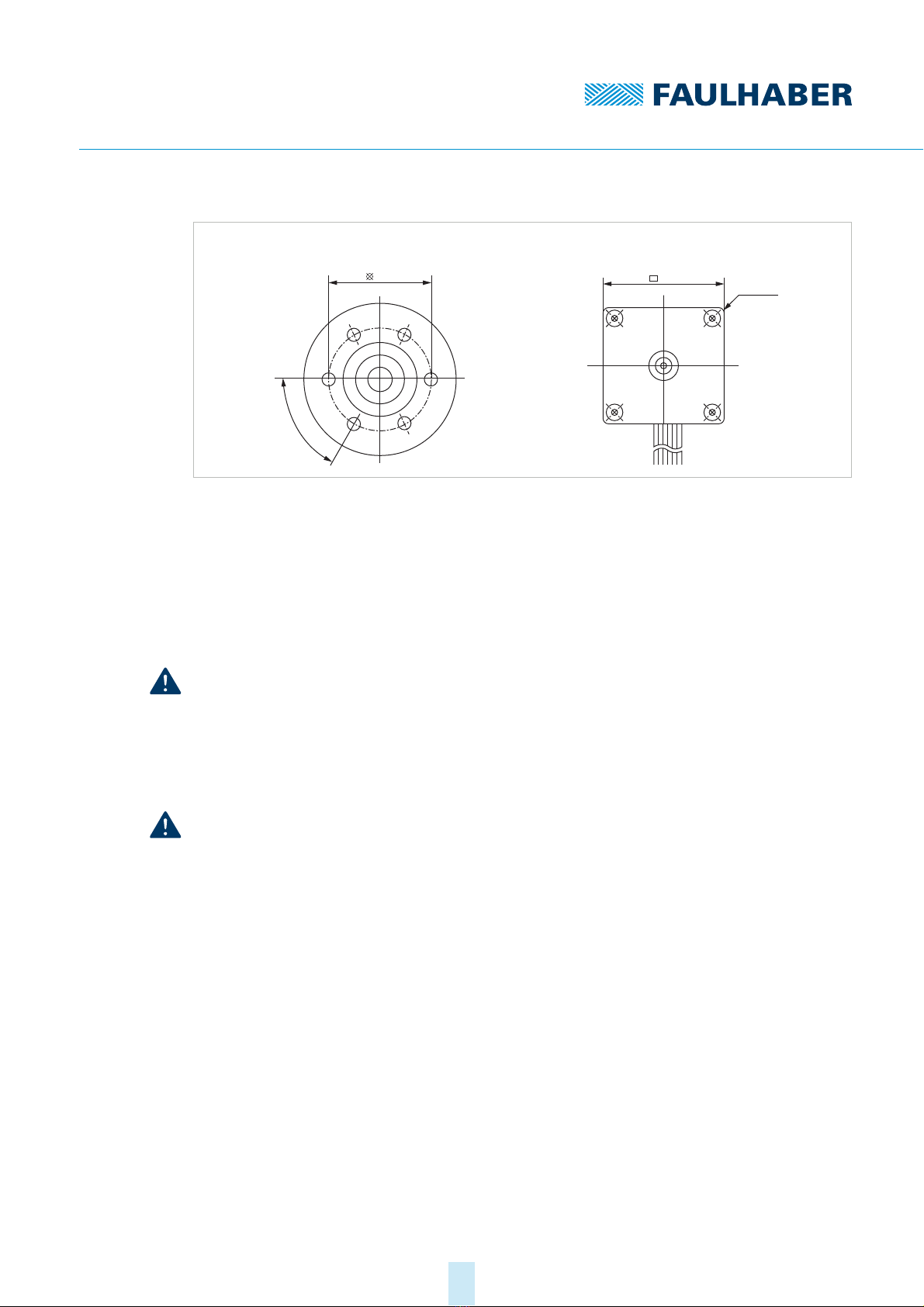
2622…B SC a)
a) Motors of model series 2610…B SC are mounted at fastening points outside the motor diameter using a quad-
ratic flange.
M2 3.5 40 20
1525…BRC M1.6 2.0 40 10
1935…BRC M2 3.0 40 15
3153…BRC M3 4.0 40 20
2214…BXT H SC M2 2.5 40 20
3216…BXT H SC M2 3.0 40 30
4221…BXT H SC M3 3.0 40 40
2nd edition, 31-03-2020 7000.05061, 2nd edition, 31-03-20207000.05061
Installation
16
Fig. 6: Comparison of round flange and quadratic flange
4.2 Electrical connection
4.2.1 Notes on the electrical connection
NOTICE!
Electrostatic discharges to the motor connections can damage the electronic components
Observe the ESD protective measures.
Carry out work only at ESD-protected workstations.
Connect the connections as per the pin assignment (see chap. 4.2.2.3, p. 19)
NOTICE!
Extreme static or dynamic loads on the ribbon cable can cause the cable to be damaged.
Make sure that the ribbon cable is not subjected to abrasion, crushing or excessively
tight bending radii during installation and operation.
With frequent bending, the bending radius must not be less than 10 mm. The possible
number of bending cycles increases as the bending radius increases.
Do not bend the cable at temperatures < –10 °C.
Comply with permissible loads (see Tab. 3).
R1,5
2610…B SC3242…BX4 SC
26
22
6x
60°

2nd edition, 31-03-2020 7000.05061, 2nd edition, 31-03-20207000.05061
Installation
17
Tab. 3: Permissible loads of the ribbon cables
Motor series Contact spacing Permissible loads
22xx…BX4(S) SC 1.27 AWG28 Tensile load: <30 N
Continuous tensile load: <17 N
Bending radius with one-off installation: >1.2 mm
32xx…BX4 SC / SCDC 2.54 AWG24 Tensile load: <60 N
Continuous tensile load: <20 N
Bending radius with one-off installation: >1.8 mm
26xx…B SC 1.00 AWG28 Tensile load: < 20 N
Continuous tensile load: < 11 N
Bending radius with one-off installation: >1.2 mm
1525…BRC / 1935…BRC 1.00 AWG28 Tensile load: < 20 N
Continuous tensile load: < 11 N
Bending radius with one-off installation: >1.2 mm
3153…BRC 1.27 AWG26 Tensile load: < 20 N
Continuous tensile load: < 17 N
Bending radius with one-off installation: >1.2 mm
2214…BXT H SC 1.27 AWG28 Tensile load: <30 N
Continuous tensile load: <17 N
Bending radius with one-off installation: >1.2 mm
3216…BXT H SC 2.54 AWG24 Tensile load: <60 N
Continuous tensile load: <20 N
Bending radius with one-off installation: >1.8 mm
4221…BXT H SC 2.54 AWG24 Tensile load: <60 N
Continuous tensile load: <20 N
Bending radius with one-off installation: >1.8 mm
2nd edition, 31-03-2020 7000.05061, 2nd edition, 31-03-20207000.05061
Installation
18
4.2.2 Electrical connection of motor
4.2.2.1 EMC-compliant installation
NOTICE!
Signal interference may be caused if the connection cables are too long.
Do not exceed a cable length of 3 m.
Observe the EMC protective measures described here.
EMC filter
Each electronics and motor supply cable must be installed directly at the unit with two
windings through a suitable ferrite sleeve (e.g. Würth Elektronik No.: 74270090).
4.2.2.2 EMC suppressor circuit
Suppressor circuit 1
Fig. 7: EMC suppressor circuit with ceramic capacitors
If a ceramic capacitor (C1) is used in the PWMnsoll operating mode: To avoid faults, use a
signal source with a low internal resistance.
To update the firmware using the Motion Manager software, remove capacitor C2.
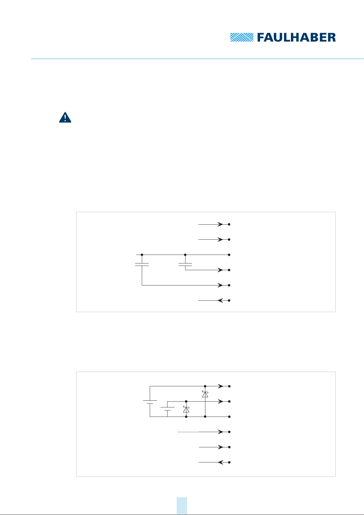
Suppressor circuit 2
Fig. 8: EMC suppressor circuit with suppressor diodes
FG
DIR
U
GND
U
U
nsoll
mot
p
C2 C1220 nF 220 nF
FG
DIR
U
GND
U
U
nsoll
mot
p
D1
D2
0 – 10 V DC

2nd edition, 31-03-2020 7000.05061, 2nd edition, 31-03-20207000.05061
Installation
19
Separated suppressor diodes (D1 and D2, e.g. P6KE33A von STMicroelectronics) for UP
and Umot in case of separated supply voltages.
If only one power supply is used (jumper between UPand Umot), one suppressor diode
(D1) is sufficient.
4.2.2.3 Pin assignment
NOTICE!
Incorrect polarity can cause irreparable damage to the electronics
Connect the motor in accordance with the pin assignment.
Motors with integrated SC have a 6-wire cable. Wire 1 is highlighted in red for all product
variants.
Tab. 4: Pin assignment of ribbon cable (SC)
Tab. 5: Electrical data – motor connections on motor series 22xx BX4(S) SC
Wire Designation Meaning
1U
pElectronics supply
2 Umot Power supply of the motor
3 GND Common ground
4 Unsoll Control voltage for the set speed (see chap. 5.2,
p. 28)
5 DIR Switching input for the rotation direction of the
motor
6FG Digital output with open collector and integrated
pull-up resistor (22 kΩ)
The digital output can be configured for various
tasks (see chap. 5.3, p. 31)
Wire Designation Value
1 (Up) Electronics supply 5…28 V DC
2 (Umot)Coil supply 6…28 V DC
3 (GND) Ground –
4 (Unsoll)
Analogue input
Input voltage Uin = 0…10 V
Uin > 10 V…Up➙speed set value not defined
Input resistance Rin≥8.9 kΩ
Speed set value pro1V,1000min
-1 (2 000 min-1 (S))
Uin< 0.15 V ➙motor stops
Uin > 0.3 V ➙motor runs
5 (DIR)
Digital input
Rotation direction input To ground or U < 0.5 V: anticlockwise
U > 3 V: clockwise
Input resistance Rin≥10 kΩ
6 (FG)
Digital output
Frequency output Max. Up, Imax = 15 mA
Open collector with 22 kΩpull-up resistor
6 lines per revolution

2nd edition, 31-03-2020 7000.05061, 2nd edition, 31-03-20207000.05061
Installation
20
Tab. 6: Electrical data – motor connections on motor series 32xx BX4 SC
Motors in the version with SCDC have a 2-wire cable. In this operating mode, the servomo-
tor is connected in the same way as a conventional DC motor. The rotation direction of the
motor is determined by the polarity of the connection wires.
Tab. 7: Pin assignment of ribbon cable (SCDC)
Tab. 8: Electrical data – motor connection (SCDC)
Wire Designation Value
1 (Up) Electronics supply 6.5…30 V DC
2 (Umot)Coil supply 6.5…30 V DC
3 (GND) Ground –
4 (Unsoll)
Analogue input
Input voltage Uin = 0…10 V
Uin > 10 V…Up➙speed set value not defined
Input resistance Rin≥8.9 kΩ
Speed set value pro 1 V, 1 000 min-1
Uin< 0.15 V ➙motor stops
Uin > 0.3 V ➙motor runs
5 (DIR)
Digital input
Rotation direction input To ground or U < 0.5 V: anticlockwise
U > 3 V: clockwise
Input resistance Rin≥10 kΩ
6 (FG)
Digital output
Frequency output Max. Up, Imax = 15 mA
Open collector with 22 kΩpull-up resistor
6 lines per revolution
Wire Designation Meaning
1 (red) Mot + Positive connection of the power supply
2Mot – Negative connection of the power supply
Wire (designation) Value Voltage
1 (Mot +) Clockwise rotation with homopolar connection
Anticlockwise rotation with oppositely poled connection
6.5…30 V
2 (Mot –)
This manual suits for next models
43
Table of contents
Other Faulhaber Engine manuals


Popular Engine manuals by other brands

Toyota
Toyota 5R 1969 Repair manual

Roma
Roma Somfy OXIMO WT Important readout instructions

SIMONINI
SIMONINI MINI 2 EVO Installation

Fuji Imvac
Fuji Imvac BT-32EIS Operator's manual

Continental Refrigerator
Continental Refrigerator Permold IOF-550-B Maintenance manual

Simu
Simu 5008030D installation instructions


