Faulhaber 2232***BX4S series User manual
EN
Brushless DC servo motors
Series 2232 … BX4(S)
Series 2250 … BX4(S)
Instruction Manual
WE CREATE MOTION


3
Version:
3rd edition, 17.09.2009
Copyright
by Dr. Fritz Faulhaber GmbH & Co. KG
Daimlerstr. 23/25 · 71101 Schönaich
All rights reserved, including those to the translation.
No part of this description may be duplicated, reproduced,
stored in an information system or processed or trans-
ferred in any other form without prior express written
permission of Dr. Fritz Faulhaber GmbH & Co. KG.
These operating instructions have been prepared with due
care.
Dr. Fritz Faulhaber GmbH & Co. KG cannot accept any
liability for any errors in these operating instructions or for
the consequences of such errors. Equally, no liability is ac-
cepted for direct losses or consequential damages resulting
from improper use of the devices.
The pertinent regulations regarding safety engineering
and interference suppression as well as the specifications
in these operating instructions must be complied with
when using the equipment.
Subject to change without notice.
The respective current version of these operating instruc-
tions is available on FAULHABER's internet site:
www.faulhaber.com
Imprint

4
1 Important Information 6
1.1 Symbols used in these operating instructions 6
1.2 Safety instructions 7
2 Description 8
2.1 General product description 8
2.1.1 Motor without attachment 8
2.1.2 Motor with encoder IE3 or IE3 L 9
2.1.3 Motor with SC speed controller 10
3 Installation 11
3.1 Assembly 11
3.2 EMC compatible installation 12
3.2.1 Description of the EMC measures 12
3.3 Connector pin assignment 14
3.3.1 Motor without attachment 14
3.3.2 Motor with encoder IE3 or IE3 L 15
3.3.3 Motor with SC speed controller 16
3.4 Connection examples 17
3.4.1 Motor without attachment 17
3.4.2 Motor with encoder IE3 17
3.4.3 Motor with encoder IE3 L 18
3.4.4 Motor with SC speed controller 19
4 Functional Description 20
4.1 Motor without attachment 20
4.1.1 Connection functions 20
4.2 Motor with encoder IE3 or IE3 L 22
4.2.1 Connection functions 22
4.3 Motor with SC speed controller 26
4.3.1 Connection functions 26
4.3.2 Configuration 28
4.3.3 Special configurations 30
4.3.4 Parameter settings 32
4.3.5 Technical information 34
5 Operation 36
5.1 Commissioning 36
6 Maintenance 37
6.1 Service/ Maintenance 37
6.2 Troubleshooting 37
Table of Contents

5
7 Technical Data 38
7.1 Motor 2232 … BX4 without attachment 38
7.1.1 Operating data 38
7.1.2 Product dimensions 39
7.1.3 Connection information 39
7.2 Motor 2232 … BX4 with encoder IE3 40
7.2.1 Operating data 40
7.2.2 Product dimensions 41
7.2.3 Connection information 41
7.3 Motor 2232 … BX4 with encoder IE3 L 42
7.3.1 Operating data 42
7.3.2 Product dimensions 43
7.3.3 Connection information 43
7.4 Motor 2232 … BX4 with Speed Controller SC 44
7.4.1 Operating data 44
7.4.2 Product dimensions 45
7.4.3 Connection information 45
7.5 Motor 2250 … BX4 without attachment 46
7.5.1 Operating data 46
7.5.2 Product dimensions 47
7.5.3 Connection information 47
7.6 Motor 2250 … BX4 with encoder IE3 48
7.6.1 Operating data 48
7.6.2 Product dimensions 49
7.6.3 Connection information 49
7.7 Motor 2250 … BX4 with encoder IE3 L 50
7.7.1 Operating data 50
7.7.2 Product dimensions 51
7.7.3 Connection information 51
7.8 Motor 2250 … BX4 with Speed Controller SC 52
7.8.1 Operating data 52
7.8.2 Product dimensions 53
7.8.3 Connection information 53
7.9 Ambient conditions 54
8 EC Directives 55
9 Manufacturer's Declaration 56
10 Warranty 57
Table of Contents

6
Important Information1
These operating instructions describe the handling and operation of the following FAULHABER
brushless DC servo motors:
Motors without attach-
ment
Motors with encoder IE3 Motors with encoder IE3 L Motors with speed controller SC
2232S012BX4 2232S012BX4 IE3 2232S012BX4 IE3 L 2232S012BX4 SC
2232S012BX4S 2232S012BX4S IE3 2232S012BX4S IE3 L 2232S012BX4S SC
2232S024BX4 2232S024BX4 IE3 2232S024BX4 IE3 L 2232S024BX4 SC
2232S024BX4S 2232S024BX4S IE3 2232S024BX4S IE3 L 2232S024BX4S SC
2250S024BX4 2250S024BX4 IE3 2250S024BX4 IE3 L 2250S024BX4 SC
2250S024BX4S 2250S024BX4S IE3 2250S024BX4S IE3 L 2250S024BX4S SC
Please read through the complete operating instructions before using the motor.
Keep these operating instructions in a safe place for later use.
The information given in these operating instructions refers to the standard version of the motors.
Please refer to any additional information sheet provided in the event of differences in information
due to a customer-specific motor modification.
Symbols used in these operating instructions1.1
WARNING! Warning!
This pictogram with the wording "Warning!" indicates an imminent danger which can result in phy-
sical injuries.
This arrow points out the appropriate action to take to prevent the imminent danger.f
CAUTION! Caution!
This pictogram with the wording "Caution!" indicates an imminent danger which can result in slight
physical injuries or material damage.
This arrow points out the appropriate precautions.f
REGULATION! Regulations, guidelines and directives
This pictogram with the wording "Regulation" indicates a statutory regulation, guideline or directive
which must be observed in the respective context of the text.
NOTE Note
This "Note" pictogram provides tips and recommendations for use and handling of the component.

7
Important Information1
Safety instructions1.2
Observance of the following safety instructions is prerequisite for trouble-free and safe operation of
the motor. Therefore, please carefully read through all the notes and follow them when using the
motor.
Intended use
The servomotor is designed as a drive for small mechanisms, as well as for continuously running and
positioning applications, e.g. pump and scanner drives or in metering technology.
External control electronics are required to operate the motors without integrated speed
controllers.
The motor contains magnetic and electromagnetic components. Any effects as well as the specific
relevant national regulations must be taken into account when using the motor.
The motor may not be used in environments where contact with water, chemicals and/or dust is
possible or in potentially explosive atmospheres!
The forces, torques and accelerations acting on the motor are limited. Seesection 7 "Technical
Data".
Please ask the manufacturer for information about individual use under special ambient
conditions.

8
Description2
General product description2.1
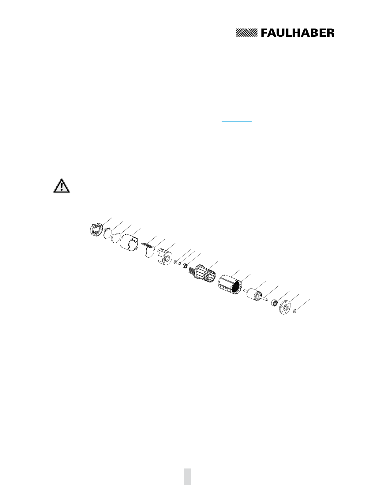
2.1.1 Motor without attachment
The servomotor is an electronically commuted (brushless) DC motor. Compared to mechanically com-
muted electric motors, its main outstanding feature is a much longer life.
The motor is based on the self-supporting coil technology, FAULHABER system, and essentially con-
sists of a three-phase winding (stator) and a four-pole permanent magnet (rotor). The commutation
takes place via an additional external control.
The rotor position is detected by 3 Hall signals.
FAULHABER's SC 2804 control is recommended for operation of the servomotor.
1
2
5
467
89
10 11 12 13 14
3
1 Cover
2 Adapter board
3 Ribbon cable
4 Press ring
5 Spring
6 Rear motor bearing
7 Winding with Hall sensors
8 Housing
9 Steel yoke
10 Rotor with permanent magnet
11 Shaft
12 Front motor bearing
13 Mounting flange
14 Press ring

9
Description2
General product description2.1
Motor with encoder IE3 or IE3 L2.1.2
In this option, the servomotor described in section 2.1.1 has an encode with 3 output channels (IE3).
A permanent magnet on the shaft generates a moving magnetic field which is measured and further
processed by means of a rotary encoder. At the encoder's outputs there are two rectangular signals,
phase-shifted by 90°, with up to 256 pulses and one index pulse per motor.
The encoder is available with different pulse rates (32, 64, 128 or 256 pulses/revolution). The pulse
rate is included in the motor designation.
Example
Motor: 2232 … BX4S IE3-128 L
Features: Motor 2232 ... BX4S with encoder, 128 pulses/rotation, line driver
Line driver
Encoders with an "L" in the encoder designation have differential encoder signal outputs. Therefore,
common-mode interferences are suppressed and longer supply connectors are enabled. The precise
function is described in section 4.2 "Motor with encoder IE3 or IE3 L".
123
6
5
4
789
10 11 12
13
14 15
16 17 18 19 20
1 Cover
2 Sealing disc
3 Built-on housing
4 Ribbon cable 1
5 Ribbon cable 2
6 Encoder board
7 Sensor magnet
8 Magnet holder
9 Mounting flange
10 Press ring
11 Spring
12 Rear motor bearing
13 Winding with Hall sensors
14 Housing
15 Steel yoke
16 Rotor with permanent magnet
17 Shaft
18 Front motor bearing
19 Mounting flange
20 Press ring
10
Description2
General product description2.1
Motor with SC speed controller2.1.3
In this equipment option, the servomotor described in section 2.1.1 has integrated commutation
electronics (SC speed controller), which provides diverse motor control possibilities.
The motor offers the following functions:
Control of the speed through set value input or control of the speed through the motor voltage.
Switchover of direction of rotation via switch input.
Reading out the speed signal via the frequency output.
CAUTION! Risk of damage
Switching over the motor's direction of rotation (reversing duty) too quickly can cause damage.
Do not use the speed controller for reversing duty.f
1234
567
8910
11
12 13
14 15 16 17 18
1 Cover
2 Sealing disc
3 Heat transfer pad
4 Built-on housing
5 Ribbon cable
6 Controller board
7 Mounting flange
8 Press ring
9 Spring
10 Rear motor bearing
11 Winding with Hall sensors
12 Housing
13 Steel yoke
14 Rotor with permanent magnet
15 Shaft
16 Front motor bearing
17 Mounting flange
18 Press ring
11
3 Installation
Assembly3.1
The servomotor must be installed according to certain specifications to prevent malfunctions and
damage.
CAUTION! Material damage
Incorrect installation or installation with the wrong fixing materials can cause irreparable damage to
the motor's function and / or damage the motor.
Observe the following assembly instructions.f
Use environment
Depending on its use, the servomotor can get very hot. Appropriate heat dissipation possibilities
must be provided.
Shaft loads
When pressing parts on the motor shaft it must be held against on the opposite side. Otherwise the
maximum allowable load values (axial at a standstill) must be noted and observed. See section 7
"Technical Data".
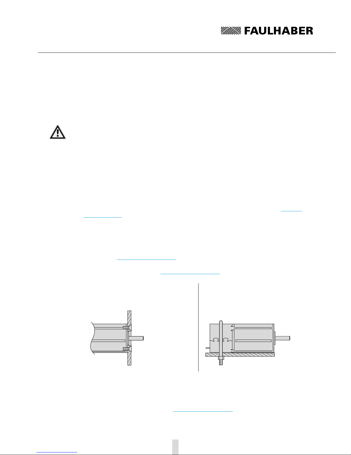
Mounting flange
When fixing the servomotor to the front flange, the screws must be locked as they can loosen
at high temperatures. The maximum length of the fixing screws must be noted and observed as
otherwise the motor will be destroyed. The depth of engagement in the motor may not exceed be
exceeded. See section 7 "Technical Data".
The maximum tightening torques are usually limited by the strength of the screws. However, they
may not exceed the data given in section 7 "Technical Data".
Right
The motor is fixed by the screws on the
mounting flange.
Wrong
The motor is securely clamped to the attach-
ment with a U-bolt.
Electrical connection
It is necessary to ensure that the ribbon cable is laid without risk of damage during installation and
operation, e.g. through chafing, squeezing or too small bending radii. The maximum load of the
cable must be noted and observed. See section 7 "Technical Data".

12
Installation3
EMC compatible installation3.2
CAUTION! Length of the connection leads
The maximum length of the connection leads is limited.
All connection leads may not exceed a length of 3 m.f
Optimisation of performance with respect to emission and immunity requires the additional EMC
measures:
Ensuring the necessary immunity in industrial uses can require use of an EMC suppressor circuit.
Motor designation Use environment Interference type Action
Motor without attachment Industrial environment
Motor with SC speed controller Industrial environment Emission EMC suppressor circuit
This table shows which additional EMC measures can be implemented to optimise the behaviour of
the equipment in the intended environment with regard to immunity.
The units are intended for industrial use only. If the devices are used in the home, in business or in
commerce or in a small business, appropriate measures must be taken to ensure that the emitted
interference is below the permitted limits!
Description of the EMC measures3.2.1
The EMC suppressor circuit (motor with Speed Controller SC only)
Circuit diagram 1
FG
DIR
Unsoll
GND
C2 C1
Umot
Up
C1 Ceramic capacitor 220 nF
C2 Ceramic capacitor 220 nF
NOTE Capacitor C1:
If the ceramic capacitor C1 is used, malfunctions can occur in PWMntarget operating mode.
Use signal source with low internal resistance in PWMntarget operating mode.f
NOTE Capacitor C2:
If using the ceramic capacitor C2, a firmware update with the Motion Manager PC firmware may no
longer be possible.
Remove the C2 capacitor when updating the firmware.f

13
Installation3
EMC compatible installation3.2
Circuit diagram 2
FG
DIR
Unsoll
GND
Umot
Up
D1
D2
0 – 10 V DC
Separate suppressor diodes (D1, D2) for Up and Umot if they
have separate supply voltages.
If only one supply voltage is used, (bridge between Up and
Umot), one suppressor diode (D1) is sufficient. D1 and D2 e.g.
P6KE33A from STMicroelectronics
NOTE Exceptions:
It may not be necessary to implement the additional EMC measures named. If the motor is fed e.g.
from a CE-conforming power supply unit, the EMC suppressor circuit can be dispensable. In this case
the power supply unit takes on the function of the EMC suppressor circuit according to circuit
diagram 2.
NOTE Motor without attachment:
A CE-conforming control, e.g. Faulhaber's SC 2804, is recommended for operation of the servomotor.

14
Installation3
3.3 Connector pin assignment
3.3.1 Motor without attachment
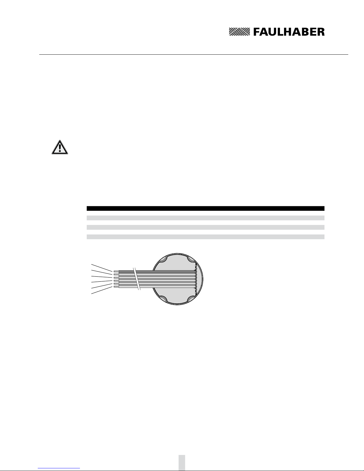
The servo motor is equipped, as a standard, with an eight-core ribbon cable for the power supply to
the sensors and phases as well as the signal transfer of the Hall sensors.
CAUTION! Electronic damage / ESD protection
Electrostatic discharges at the connection pin assignment of the ribbon cable can result in irreparable
damage to the motor.
It may only be processed in ESD protected workplaces.f
Incorrect connection of the cores can cause damage to or destruction of the electronics.
Connect the ribbon cable in accordance with the connector pin assignment, see table.f
Connection pin assignment of the ribbon cable
Core Function Value
1 (red) Phase C
2 Phase B
3 Phase A
4 GND
5 UDD 2.2 … 18 V DC
6 Hall sensor C
7 Hall sensor B
8 Hall sensor A
1
2
3
4
5
6
7
8

15
Installation3
Connector pin assignment3.3
Motor with encoder IE3 or IE3 L3.3.2
Apart from the eight-core connection cable for supplying the motor described in section 3.3.1, the
servomotor with encoder also has a six-core ribbon cable (ten-core in encoders with line driver) for
the encoder's connections.
CAUTION! Electronic damage / ESD protection
Electrostatic discharges at the connection pin assignment of the ribbon cable can result in irreparable
damage to the motor.
It may only be processed in ESD protected workplaces.f
Incorrect connection of the cores can cause damage to or destruction of the electronics.
Connect the ribbon cable in accordance with the connector pin assignment, see table.f
Connection pin assignment of the ribbon cable for encoders without line driver (IE3)
Core Function Value
1 (red) n.c.
2 Channel I (index)
3 GND Enc
4 UDD Enc 4.5 … 5.5 V DC
5 Channel B
6 Channel A
1
2
3
4
5
6
Ader 1 Motoranschlusskabel
Connection pin assignment of the ribbon cable for encoders with line driver (IE3 L)
Core Function Value
1 (red) n.c.
2 UDD Enc 4.5 … 5.5 V DC
3 GND Enc
4 n.c.
5Channel A
6 Channel A
7Channel B
8 Channel B
9Channel I (Index)
10 Channel I (Index)
1
2
3
4
5
6
7
8
9
10 Ader 1 Motoranschlusskabel
16
Installation3
Connector pin assignment3.3
Motor with SC speed controller3.3.3
The servomotor with integrated SC speed controller is equipped with a six-core ribbon cable for the
power supply and control of the motor functions.
CAUTION! Electronic damage / ESD protection
Electrostatic discharges at the connection pin assignment of the ribbon cable can result in irreparable
damage to the motor.
It may only be processed in ESD protected workplaces.f
Incorrect connection of the cores can cause damage to or destruction of the electronics.
Connect the ribbon cable in accordance with the connector pin assignment, see table.f
Connection pin assignment of the ribbon cable for motor with commutation electronics
Core Function Value
1 (red) UP5 … 28 V DC
2 Umot 6 … 2 · UN(max. 28 V DC)
3 GND
4 Untarget 0 … 10 V DC | > 10 V DC … max. UPnot defined
5 DIR to earth or U < 0.5 V = anti-clockwise, U > 3 V = clockwise
6 FG (max. UP, Imax 15 mA) 6 pulses per revolution
1
2
3
4
5
6

17
Installation3
3.4 Connection examples
Motor without attachment3.4.1
UDD
GND
Phase A
Phase B
Phase C
FAULHABER SC 2804 S
Hall sensor A
Hall sensor B
Hall sensor C
VCC
SGND
Mot A
Mot B
Mot C
Sens A
Sens B
Sens C
In the example the servomotor is operated with the FAULHABER control SC 2804 S.
Motor with encoder IE33.4.2
UDD
GND
Phase A
Phase B
Phase C
motor controller
Hall sensor A
Hall sensor B
Hall sensor C
VCC
SGND
Mot A
Mot B
Mot C
Sens A
Sens B
Sens C
GND Enc
Channel I
Channel A
Channel B
UDD Enc
Channel I
Channel A
Channel B
18
Installation3
Connection examples3.4
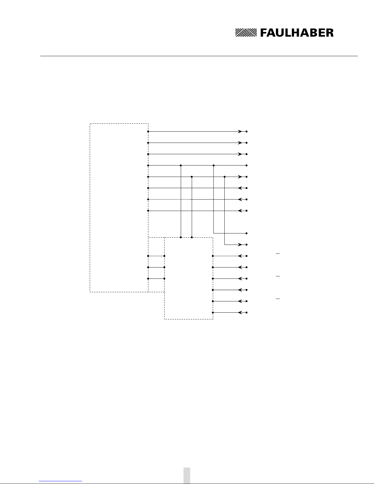
Motor with encoder IE3 L3.4.3
UDD
GND
Phase A
Phase B
Phase C
motor controller
Hall sensor A
Hall sensor B
Hall sensor C
VCC
SGND
Mot A
Mot B
Mot C
Sens A
Sens B
Sens C
GND Enc
Channel B
Channel A
Channel A
UDD Enc
Channel I
Channel B
Channel A
Channel I
Channel I
Channel B
ST26C32A
GND VCC
BIN1
AIN2
AIN1
CIN2
CIN1
BIN2
COUT
BOUT
AOUT
The differential encoder signals are joined with a TIA-422 compatible receiver module on the con-
nection side (here: ST26C32A).
19
Installation3
Connection examples3.4
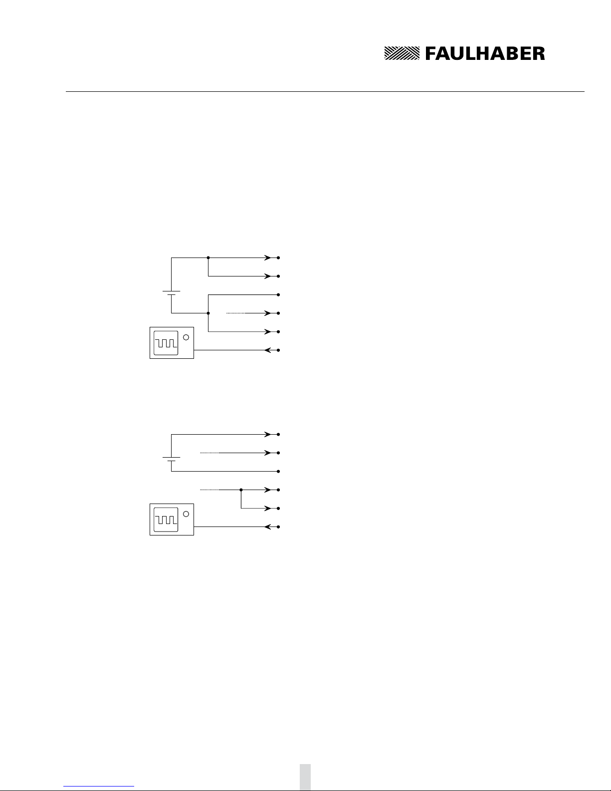
Motor with SC speed controller3.4.4
Two examples are given and are intended to clearly explain the operating modes of the servomotor
with SC Speed controller. The figures given refer to a motor with a nominal voltage of 12 V.
Electronic speed control
FG
DIR
Unsoll
GND
Umot
Up
12 V
DC
+ 3 V DC
ca. 300 Hz
+
–
The motor rotated anti-clockwise with approx. 3000 rpm, the speed is controlled electronically.
External speed control
FG
DIR
Unsoll
GND
Umot
Up
12 V
DC 0 V DC – 2 x UN
(max. 28 V DC)
+ 10 V DC
ca. 190 Hz
+
–
The motor rotates e.g. with 1900 rpm in a clockwise direction, the speed is controlled by the motor
voltage (Umot). Approx. 190 Hz is measured at the frequency output (FG).
190 pulses/sec = 31.66 rev/sec,
31.66 rev/sec = 1900 rpm.

20
Functional Description4
Motor without attachment4.1
4.1.1 Connection functions
The servomotor requires and external control for operations and has the connection options listed in
section 3.
Phase C to Phase A (core 1 – 3)
The rotating field required to operate the motor is applied to phases C to A.
Voltage range: 0 V AC to Umax.
The following limits must be adhered to for Umax:
Note and observe limit speed (seesection 7 "Technical Data").
Umax < 50 V AC (below the Low Voltage Directive).
CAUTION! Harmonic components
When the servomotor is operated with block commutation or PWM, harmonic components can arise,
as a result of which the emission behaviour of the motor can worsen.
Ensured operation of the motor within the EMC requires a harmonic-free rotating field, or thef
suggested FAULHABER control (see section 3.4 "Connection Examples").
GND (core 4)
Joint ground of the hall sensors.
UDD (core 5)
Joint power supply of the hall sensors.
Voltage range: 2.2 … 18 V DC.
Input current: < 18 mA.
Output signals Hall sensor C to Hall sensor A (core 6 – 8)
Signal output of the Hall sensors.
Voltage range: 0.1 V DC … UDD.
Output current: < 25 mA.
The output current results from the applied pull-up voltage and the pull-up resistance used.
Signal setup: The Hall signals are 120° out of phase with each other according to the phases. Due to
the 4-pole version, the switching frequency is twice as high as the speed.
This manual suits for next models
27
Table of contents
Other Faulhaber Engine manuals


