Fauser Elektrotechnik Lightmeter LM10 User manual

Lightmeter LM10
Summary
1. Introduction..................................................................................................................................2
1.1. Commissioning.....................................................................................................................2
1.2. Device description................................................................................................................3
2. Display.........................................................................................................................................4
2.1. Measured value displays......................................................................................................4
2.2. Additional in ormation...........................................................................................................4
3. Functions......................................................................................................................................5
3.1. Button unctions....................................................................................................................5
3.2. Acoustic display....................................................................................................................6
3.3. Audio unctions.....................................................................................................................6
3.4. Switching o measurement unction......................................................................................7
4. Device settings.............................................................................................................................8
4.1. Functions o data logger.......................................................................................................8
4.2. Functions o settings.............................................................................................................9
4.3. Settings menu.......................................................................................................................9
5. Data logger.................................................................................................................................11
5.1. Continuous measurements.................................................................................................11
5.2. Single-spot measurement...................................................................................................11
5.3. Data set management........................................................................................................11
5.4. Trans erring data sets.........................................................................................................12
6. Measurement.............................................................................................................................13
6.1. Preparation or measurement.............................................................................................13
6.2. Measurement o the visible spectrum with the measuring probe VL10...............................13
6.3. Calculation o licker component.........................................................................................14
6.4. Measuring the lickering rate and lickering requency........................................................14
6.5. Measurement o the in rared spectrum with the measuring probe IR10.............................16
6.6. Measurement o the ultraviolet spectrum with the measuring probe UV10.........................16
6.7. Measurement o the colour temperature with the measuring probe TF10...........................17
6.8. Signal analysis at the voltage output..................................................................................17
7. So tware FM-Data......................................................................................................................18
7.1. The program FM-Data........................................................................................................18
7.2. Installing FM-Data on Windows 2000/XP...........................................................................18
7.3. Installing FM-Data on Windows Vista/7/8/10......................................................................18
7.4. Installation o the USB-Driver or the Lightmeter LM10 on Windows 2000/XP....................20
7.5. Installation o the USB-Driver or the Lightmeter LM10 on Windows Vista/7/8/10..............21
7.6. Running FM-Data...............................................................................................................23
7.7. Trans erring and Displaying Datasets.................................................................................24
7.8. Graph and report................................................................................................................25
7.9. Cutting down datasets........................................................................................................27
7.10. Print and Export................................................................................................................27
7.11. Modi ying o the instrument settings o the LM10L............................................................28
7.12. Help Function....................................................................................................................28
8. Appendix....................................................................................................................................29
8.1. Power supply......................................................................................................................29
8.2. Maintenance.......................................................................................................................29
8.3. Firmware.............................................................................................................................29
8.4. Technical in ormation..........................................................................................................30
8.5. Description o the pin assignment o the output voltage Lightmeter LM10S/LS..................31
8.6. Scope o Delivery................................................................................................................31
8.7. Disposal..............................................................................................................................32
This manual re ers to LM10-Firmware 1.09 and FM-Data program version 2.2.0.0.
The current version o the manual is available on the homepage www.fauser.biz.
Technical changes reserved; we do not accept liability or any errors.
1

Lightmeter LM10
1. Introduction
The Lightmeter LM10 is an innovative new development or checking the quality o light sources.
For this, the parameters such as illumination intensity, licker requency and licker rate are
measured. Moreover, the lickering o lamp can be illustrated acoustically in audible as well as
ultrasonic range via a loudspeaker.
The in rared and ultraviolet range as well as the colour temperature and colour spectrum can also
be measured via optional probes.
Furthermore, the Lightmeter LM10L has an integrated data logger with 1 GB data memory and a
real-time clock or an exact time/date speci ication.
The logger has 2 operation modes: For the long term measurement o duration modes, or punc-
tual recording the single-point measurement.
Reading the stored measured values and the clearly laid-out settings o LM10L unctions on PC is
done on PC via USB inter ace. The FM-Data so tware serves or the processing and documenta-
tion o recorded measured values.
1.1. Commissioning
Please carry out the ollowing work steps sequentially be ore taking irst measurement:
● insert the batteries in the battery compartment.
● Insert the desired sensor in the sensor connector.
● Switch on LM10 by pressing the On/Sound button or two seconds.
● A ter the so tware version is displayed, the updated measured values appear on the display.
The LM10 is now ready or operation.
2

Lightmeter LM10
1.2. Device description
Figure 1: Lightmeter LM10
➊ Display (→ 2)
➋ On/Sound button (→ 3.1)
➌ Audio/USB button (→ 3.1)
➍ Selection/Menu button (→ 3.1)
➎ Record button (→ 3.1)
➏ USB port (only LM10L/LS)
For connecting the Lightmeter FM10L/LS with a PC and or power supply with the USB-power
supply (Art.-No. 520) using the attached USB-cable.
➐ Voltage output (→ .8 5) (only LM10S/LS)
Voltage output o single measured variables
➑ Sensor connector
For inserting the various measuring probes.
➒ Headphone connector
A headphone can also be connected or audio unctions instead o integrated loudspeaker.
The loud speaker is then deactivated.
3
Lightmeter LM10
2. Display
The Lightmeter LM10 has a two-line display or presenting measured values, unctions and setting
menu.
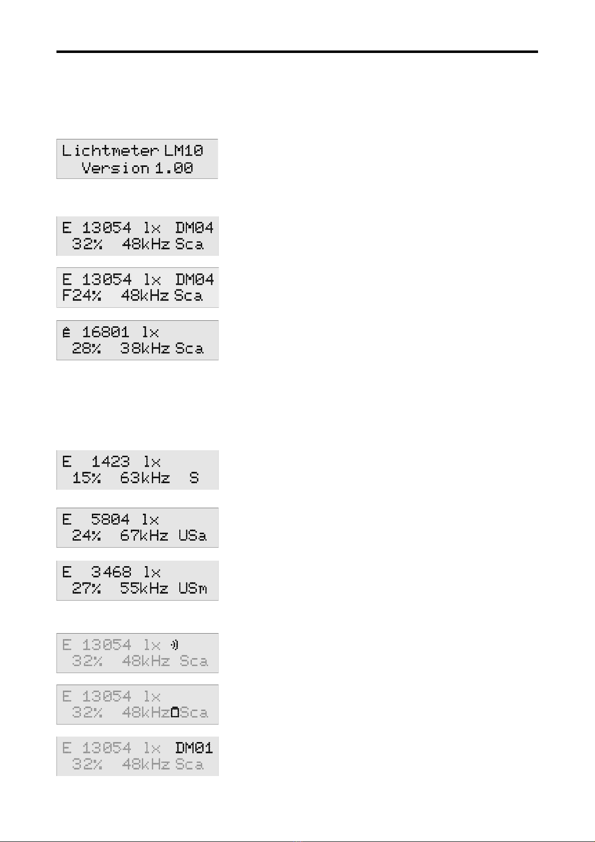
The so tware version is displayed when switched on
2.1. Measured value displays
In the standard display, the illumination intensity in Lux and
active recording o a data record is visible in the irst line. Below
it, the licker rate in % as well as the highest requency or
lickering can be read. ″Sca″ stands or Scan mode or
measuring licker requency.
With ″F″ in ront o the licker value, the value is Flicker% other-
wise ripple content.
The display can switch between various measuring probes with
the Selection button:
- visible light E
- max value Ê
- in rared light IR
- ultraviolet light UV
- colour temperature TF
2.2. Additional information
When ″S″ is displayed in second line, the audio mode or
audible range is active.
″USa″ stands or automatic ultrasonic range, the most distinct
ultrasonic requency is trans ormed in audible requency range.
″USm″ displays the manual ultrasound mode. Here, the ultra-
sonic requency, which is trans ormed in audible requency
range, is set manually via buttons. This is possible in 1 kHz
levels in a range rom 10 kHz to 400 kHz.
Sound symbol: Displays which unction is given the acoustic
display.
Battery symbol: Batteries should be exchanged as soon as
possible.
Logger unction: Displays an active logger unction.
4

Lightmeter LM10
3. Functions
3.1. Button functions
The our buttons have double unctions; the main unctions can be called up promptly in the
measuring mode. The buttons help in navigation in menu mode. All the button unctions are speci-
ied in table 1.
On/Sound utton:
I this button is pressed or two seconds, the LM10 is switched on or o . When pressed brie ly,
the acoustic display (→ 3.2) is activated. This button has an Esc- unction in menu mode.
Audio/USB utton:
With this, the various audio unctions or audible range and ultrasonic range can be activated
with automatic and manual requency setting.
By pressing the button or two seconds, the LM10 is switched to USB mode (→ 7.7, 7.11). Back
is selected in the menu mode with this.
Selection/Menu utton:
Various measuring probes are selected with this (→ .3 4.) The sensor or visible light is
displayed by de ault. The requency scan is restarted in the automatic ultrasonic mode. The
requency is increased in manual ultrasonic mode. By pressing the button or two seconds,
LM10 is switched to menu mode (→ 4.3). Next is selected in menu mode.
Record utton:
Activating logger unction in LM10L/LS (→ 5). The measurement recording is started or ended
in the duration mode. In the single-spot mode, the measurement is opened and the respective
value is taken when the button is kept pressed urther. By pressing the button or two seconds,
the last measured value is saved and the measurement ends. The unction o this button is
Se ection→Enter in menu mode.
With this, the requency is reduced in the manual ultrasonic range.
In Peak-Hold mode, the Peak-Hold display can be reset.
5
Lightmeter LM10
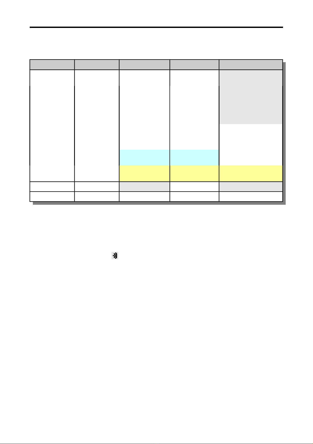
All the unctions o various buttons are illustrated in the ollowing table. The buttons saved in light-
grey colour are available only in Lightmeter LM10L/LS.
Button: Sound Audio Selection Record
pressed brie ly sound o o illumination
intensity E
start recording
sound
illumination
intensity
audible range in rarot IR end recording
sound
licker rate
ultraviolet UV store single-spot
colour
temperature T
Peak-Hold →Peak-Hold delete
ultrasonic →
automatic
start scan
ultrasonic →
manually
increase
requency
decrease requency
pressed or 2s on/o USB-mode Menu-mode leave single-spot
in menu Esc back next selection/enter
Tab e 1: Button functions of Lightmeter LM10
3.2. Acoustic display
The acoustic display is controlled via the On/Sound button. The sound signal proportional to
measured values can be allocated to illumination intensity or licker rate or deactivated. The unc-
tion is displayed by the symbol .
3.3. Audio functions
The Lightmeter LM10 has three audio unctions to show the lickering o lamps acoustically. The
various audio modes can be selected by pressing the Audio button.
Scan mode
Shows the licker rate in % and the dominant licker requency in kHz. The acoustic reproduc-
tion is inactive. This mode is shown by ″Sca″ on display. I the illumination intensity is less than
50 lx or greater than 20 klx, a question mark is displayed in licker requency and licker rate as
no distinct speci ication o values is possible in such conditions. A licker rate o at least 5% is
necessary or displaying requency.
Audi le range
With this, the lickering is reproduced in the requency range rom 50 Hz to 16 kHz directly via
the loudspeaker. Flicker rate is displayed in % and the dominant lickering requency in kHz in
scan mode. This mode is signaled with ″S″.
Automatic ultrasonic
This mode trans ers the lickering in requency range rom 10 kHz to 400 kHz in audible
requency range. The LM10 thus scans the dominant licker requency and trans ers it optimally
6

Lightmeter LM10
in the audible range. I no dominant requency is available in the range between 10 kHz and
400 kHz, the starting requency 10 kHz is reproduced. The scan process can be repeated by
pressing the Selection button. The dominant licker requency is displayed, ″USa″ appears
on display in this mode.
Manual ultrasonic
A requency range rom 10 kHz to 400 kHz can be run manually at kHz levels. The reproduced
requency is increased with the Selection button, decreased with the Record button. The
currently set requency is displayed, ″USm″ appears in this mode.
The audio unctions are reproduced via the integrated loudspeaker by de ault. Optionally, a head-
phone can be connected to the headphone connector; then the loudspeaker becomes inactive.
Using a headphone is recommended in noisy surrounding or in case o deeper requencies as
reproduction by loudspeaker is limited here.
3.4. Switching of measurement function
Besides the standard measuring probe, various other measuring probes can be operated on Light-
meter LM10 or the range o visible light. For this, the measurement unction corresponding to that
probe is selected via Selection button.
The unction o measuring probes is described in Chapter Measurement (→ 6).
This additional probe must be activated in menu via the unction Setting→Probe X or operation.
Moreover, the peak-value display or standard measuring probes is selected via Selection
button. The peak values are indicated by the symbol Ê; the peak value can be deleted via the
menu unction Peak-Hold or Record button.
7

Lightmeter LM10
4. Device settings
Here all the setting options o the Lightmeter LM10 are described, the unctions o the data logger
are available only in the versions LM10L/LS.
The logger settings and device settings can be made directly on LM10 using the settings menu
(→ 4.3) and or LM10L/LS settings can be adjusted using the program FM-Data on the PC. For
this, connect LM10L with the PC using the USB cable and switch to the USB mode by pressing the
Audio/USB button or two seconds (→ 7.11).
4.1. Functions of data logger
Display data memory:
The data records saved in the device are presented with data record name and starting time o
recording.
Using the Selection and Audio buttons, the data records can be scrolled through (→ 5.3).
Delete data memory:
Delete all the stored data records.
Logger mode:
Here, one can select one o the two data logger modes – Continuous measurement and sing e-
spot measurement (→ 5).
Measurement interval:
Selection o recording interval or the unction Continuous measurement o data logger.
USB transfer:
With this, the trans er speed o USB connection can be set. The S ow unction guarantees a
stable connection on most o the computers. With the Fast option, up to twenty times aster
data trans er is possible. However, this could lead to trans er errors in some computers, espe-
cially notebooks.. Then select the S ow option.
8

Lightmeter LM10
4.2. Functions of settings
Threshold value %:
Varying threshold values can be selected or licker rate. An alert sounds when the threshold
value is exceeded.
Measuring pro e IR:
When this menu unction is activated, the in rared spectrum can be displayed via the
Selection button.
Measuring pro e UV:
When this menu unction is activated, the ultraviolet spectrum can be displayed via the
Selection button.
Measuring pro e TF:
When this menu unction is activated, the colour temperature can be displayed via the
Selection button.
LCD lighting:
Setting the duration o background light or display. I duration o 1 Minute is selected, the light
extinguishes one minute a ter the last button press.
Volume:
Two volumes can be selected or audio unction.
Tone generator:
Selection o the characteristic o tone signal proportional to ield intensity (→ 3.2).
Calculation %:
Calculation type o the light licker.
Signal tone:
Activate/deactivate a beep sound when pressing the button.
Auto-Power-Off:
I the Auto-power-off unction is active, the LM10 switches o ive minutes a ter the last button
press in order to prolong the battery li e.
4.3. Settings menu
When the Selection/Menu button is pressed or two seconds, the Lightmeter LM10 is in menu
mode. Here logger settings as well as device settings can be adjusted.
For navigation use the buttons as shown in table 1.
Button: Sound Audio Selection Record
Esc Back Next Selection/Enter
Tab e 2: Button functions Lightmeter LM10 in settings menu
All the settings options are speci ied in the ollowing table 3. The values o standard settings are
presented in bold ont. The unctions saved in light grey are available only or LM10L/LS.
9

Lightmeter LM10
Menu →Data logger →Data memory →Display → Data record
Delete
Logger mode →Continuous measurement
Single-spot
Sample interval →0,25 seconds
1 second
10 seconds
1 minute
USB-Trans er →langsam
schnell
Settings →Threshold value % →None
5%
10%
20%
50%
Measuring probe IR →Activate
Deactivate
Measuring probe UV →Activate
Deactivate
Measuring probe TF →Activate
Deactivate
LCD lighting →o
1 minute
permanent
Volume →Low
High
Tone generator →Steep
Flat
Calculation →Ripple content
Flicker%
Signal sound →Activate
Deactivate
Auto-Power-O →Activate
Deactivate
Delete Peak-Hold
Tab e 3: Functions in menu mode
10

Lightmeter LM10
5. Data logger
The data logger o the Lightmeter LM10L/LS has two operating modes. These modes can be
selected in the device settings under Data ogger→Logger mode.
5.1. Continuous measurements
In continuous mode the measured values are recorded with the speci ied measurement interval.
The recording can be started and ended using the Record button.
The display ″DM″ appears in case o continuous measurement,
the ollowing number shows the data set number.
By de ault the 10 second measurement interval is set, however, the interval can be varied between
0.25 seconds and one minute in the menu using the Data ogger→
Samp e
interva unction. For a
measurement interval o one minute, the operating time is extended with the power saving mode
to approx. one week.
5.2. Single-spot measurement
In the single-spot mode individual measured value ranges, e.g. or di erent light sources, can be
saved. Per data set a maximum o 20 measuring points can be accepted.
The data set can be opened and the individual measuring points can be accepted using the
Record button. In the display the number o individual measuring points are displayed. The
dataset is closed automatically a ter the twentieth measuring point or it can be closed early by
pressing the Record button or two seconds.
″EP″ stands or single-spot measurement, ollowed by the
dataset number. A ter the ″#″-symbol the number o the
measuring point is displayed.
5.3. Data set management
The LM10 gives comprehensive in ormation on all the data sets in the memory.
For this call up the menu Menu→Data ogger→Data memory→Disp ays.
In the irst line the number o the datasets in the memory is
displayed.
In the second line the recording type ″DM″, continuous measu-
rement, ″EP″ single-spot measurement and the dataset
number, start time and date are displayed.
The statistical values o the data set can be called up using the
Record button.
The navigation between the di erent datasets takes place
using the Selection button previous and the Filter button
back.
Leave the display with the On/Sound button Esc.
11

Lightmeter LM10
5.4. Transferring data sets
By pressing the Audio/USB button or two seconds, the LM10L/LS switches to the USB mode and
in display appears: ″USB mode: Waiting for PC″.
Now the communication between the Lightmeter LM10L/LS and the PC is possible through the
USB cable.
The communication takes place using the Program FM-Data as described in Chapter 7.7.
You can exit the USB mode using the Esc unction o the On/Sound button.
12

Lightmeter LM10
6. Measurement
6.1. Preparation for measurement
Insert the measuring probe, required or measuring, in the sensor connector o Lightmeter LM10.
The measuring probe can also be connected to LM10 via 80 cm long connecting cable. Select the
corresponding measurement unction via the Selection button.
The in luences o other light sources should be avoided i a single lamp is to be measured. When
measuring the compact luorescent lights (energy saving lamps), it must be taken into account that
they attain their ull light intensity a ter ew minutes.
6.2. Measurement of the visi le spectrum with the measuring pro e VL10
The measuring probe VL10 provided with the Lightmeter LM10
combines the measurement o the illumination intensity E in
Lux, the licker rate in % and the licker requency up to 400
kHz using the quick precision ampli ier.
The maximum values (peak hold) o illumination intensity and
licker rate can be displayed using the Selection button. The
maximum values can be reset with the Record button.
The measured spectrum covers the visible range rom 480 nm
to 660 nm.
The spectral sensitivity V(λ) o the measuring probe is adjusted
to that o the human eye.
Spectra sensitivity of the measuring probe VL10
13
Lightmeter LM10
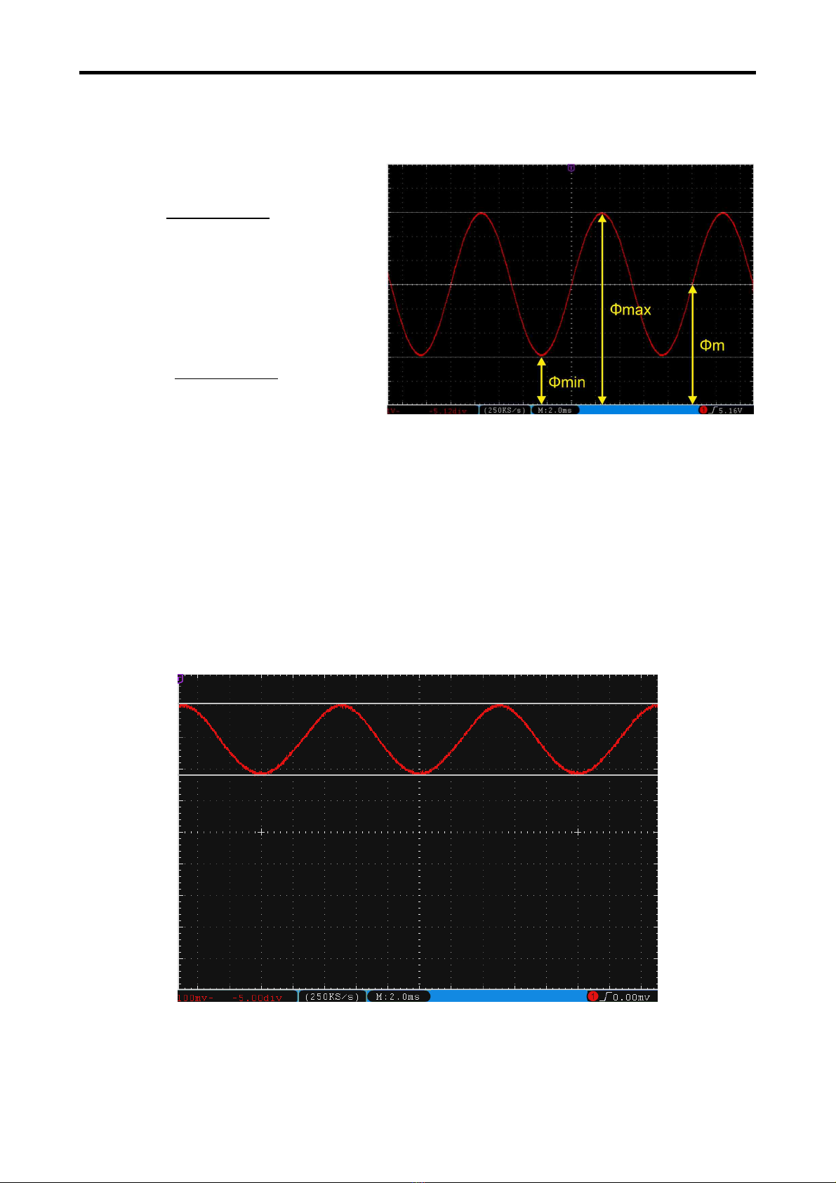
6.3. Calculation of flicker component
LM10 calculates the licker component according to the ollowing selectible procedures:
Ripple content:
In accordance with the Standard of
Bui ding Bio ogy Testing Methods
SBM-2015.
Flicker%:
In accordance with IESNA.
Luminous lux ϕ in Lumen (lm)
6.4. Measuring the flickering rate and flickering frequency
The visible spectrum must be measured using the measuring probe VL10.
To precisely measure the licker rate and licker requency o a lamp, the in luence o other light
sources including daylight must be avoided. The measurement must there ore be carried out in a
dark room.
The LM10 must be aligned directly to the lamp using the measuring probe VL10 and get it closer
till the measured values are stable.
Brightness of an incandescent amp (F icker rate 23%, f icker frequency 100 Hz)
14
W=Φmax – Φmin
Φmax ∗100%
F%=Φmax – Φmin
Φmax+Φmin ∗100%

Lightmeter LM10
In case o incandescent lamps and halogen lamps, the licker requency is always 100 Hz and the
lickering rate is rom 15% to 25%. Low-volt halogen lamps with electronic power supply are an
exception.
Brightness of a compact f uorescent amp (F icker rate 31%, f icker frequency 49 Hz)
Compact luorescent lamps also known as energy-saving lamps have a licker requency in the
range rom approx. 20 kHz to 150 kHz due to the integrated electronic power supply. The lick-
ering rate is typically rom 20% to 40%.
Brightness of an LED amp (F icker rate 100%, f icker frequency 49 Hz)
As the brightness o an LED responds almost without lag to its operating current, a general state-
ment on the licker rate and licker requency or these lamps is not possible.The licker rate can lie
between 0% to 100%, depending on the voltage source used (power supply). Flickering requecies
o 50 Hz to a ew 100 kHz are possible. Hence, the quality o the voltage source is o greater
importance in LED lamps.
15
Lightmeter LM10
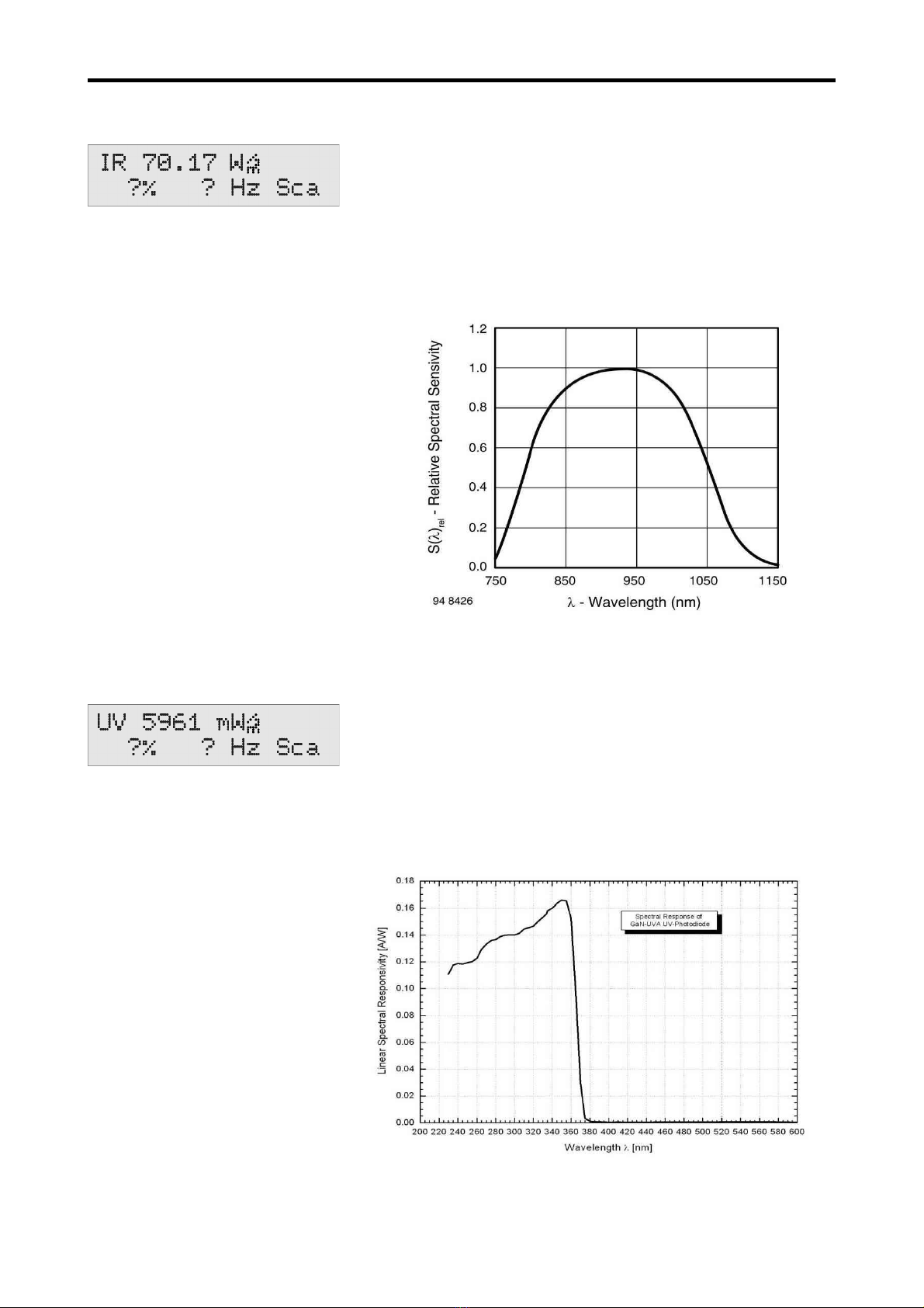
6.5. Measurement of the infrared spectrum with the measuring pro e IR10
With the measuring probe IR10 (Article no. 263), the in rared
spectrum can be measured in the range (λ0.5) rom 790 nm to
1050 nm. The unit is W/m². Select the IR unit or the in rared
range using the Selection button. For this, the unction
Settings→Measuring Probe IR must be activated. The display o
the licker requency and the ultrasound audio unctions are
possible in a requency range up to 400 kHz.
Spectra sensitivity of the measuring probe IR10
6.6. Measurement of the ultraviolet spectrum with the measuring pro e UV10
With the measuring probe UV10 (Article no. 265), the ultraviolet
spectrum can be measured in the range (λ0.5) rom 220 nm to
365 nm. The unit is mW/m². Select the UV unit or the ultravi-
olet range using the selection button. For this, the unction
Settings→Measuring Probe UV must be activated.
Display o licker requency is not possible and the ultrasound
audio unctions are inactive.
Spectra sensitivity of the measuring probe IR10
16

Lightmeter LM10
6.7. Measurement of the colour temperature with the measuring pro e TF10
For this, the measuring probe TF (Article no. 266) must be used
and the T unit or the colour temperature must be selected
using the selection button.
For this, the unction Settings→Measuring Probe TF10 must be
activated.
The unit or the colour temperature is K (Kelvin). The measure-
ment range is rom 2000 K to 3500 K.
The display o the licker rate, the licker requency and the
audio unctions are not available.
6.8. Signal analysis at the voltage output
The Lightmeter LM10S/LS has a voltage output or signal analysis (→ 8.5).
The entire measurement signal (AC and DC) is at connection no. 1 and only the AC signal is at
connection no. 2. The AC voltage signal has auto range and is boosted by the actor ten under
1000 lx.
The brightness o a lamp can be made visible on the entire signal with an oscilloscope. The
requency spectrum o the licker requencies are seen with a requency analyser.
Frequency range of a compact f uorescent amp
17

Lightmeter LM10
7. Software FM-Data
7.1. The program FM-Data
The Lightmeter LM10L possesses a data logger which provides the storage o measurement
values over a long period. The program FM-Data enables the trans er o the recorded data to the
PC as well as their graphic illustration and printing. Moreover, FM-Data allows to readout and
change the settings o the Lightmeter LM10L and the Fieldmeter FM10L as well as the trans er o
the new setup to the LM10L.
The latest version can be ordered at our homepage www.fauser.biz. FM-Data is constantly devel-
oped to adapt to the needs o our customers, and this service is available to you in the orm o ree
o charge updates.
7.2. Installing FM-Data on Windows 2000/XP
The so tware CD bundled with the Fieldmeter FM 10 contains the installation program setup.exe,
which installs the program FM-Data on your PC.
You should close all other applications be ore starting the installation. A ter that start setup.exe
and ollow the instructions o the installation program.
7.3. Installing FM-Data on Windows Vista/7/8/10
You should close all other applications be ore starting the installation. A ter that start setup.exe on
the so tware CD FM-Data and ollow the instructions o the installation program.
A ter the installation, open the windows explorer and choose the older C:\programme(x86)
\Fauser E ektrotechnik\FM-Data. Right-click on the application FM-Data and choose the menu
point attributes.
Now select compatibi ity.
Klick the button settings for a users.
18

Lightmeter LM10
Activate the authorisation level: Execute
program as administrator.
19
Lightmeter LM10
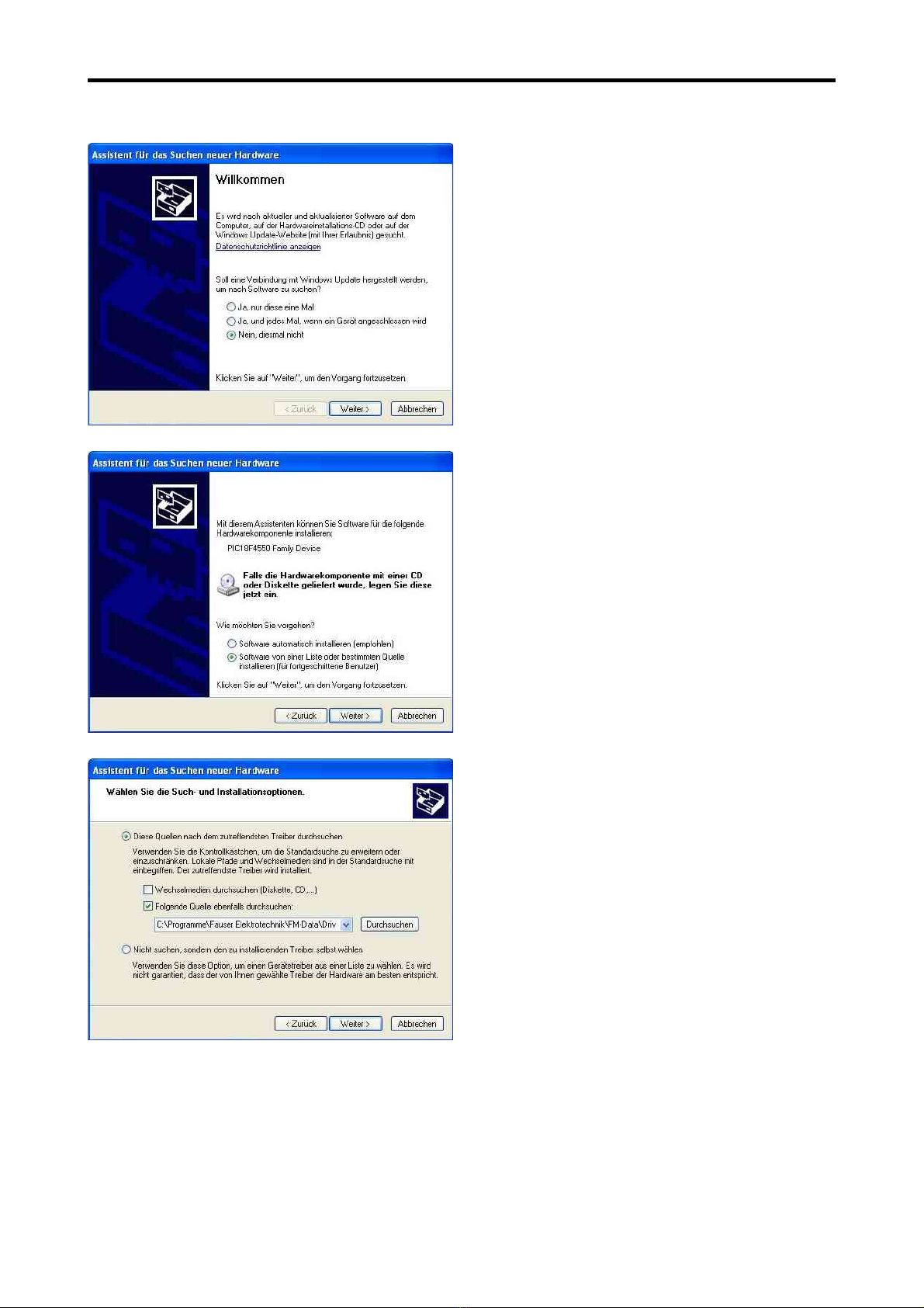
7.4. Installation of the USB-Driver for the Lightmeter LM10 on Windows 2000/XP
Connect the Lightmeter LM10L to your PC via
the USB-cable. Turn on the LM10L and acti-
vate USB-mode (→ 3.1). The window o the
hardware assistant appears on the screen.
Choose the answer No not this time to the
question or a Windows-update. Click on
continue.
Now, choose insta software from a ist or
certain source and click on continue.
Enter the source o the driver:
C:\programs\Fauser E ektrotechnik\FM-Data
\driver.
I the FM-Data CD is in the drive you can also
enter search or CD-ROM drive.
C ick on continue.
20
This manual suits for next models
7
Table of contents
Popular Measuring Instrument manuals by other brands

RBR
RBR quartz3 BPR zero Guide

Garmin
Garmin LIDAR-Lite v1 Silver Label operating manual

Hioki
Hioki L2003 user manual

Keysight Technologies
Keysight Technologies B2900A Series Demo guide

Invacare
Invacare CHECK O2 PLUS Assembly, installation and operating instructions

LaserLine
LaserLine MoistureFinder Compact manual


Lord MicroStrain
Lord MicroStrain G-Link2-LXRS user manual

Ecolab
Ecolab Nalco Water STORM Settling Rate Monitor Installation, operation & maintenance manual

Netatmo
Netatmo Smart Anemometer manual

Unipulse
Unipulse F320 Operation manual

Honeywell
Honeywell FE260 operating instructions

Hanna Instruments
Hanna Instruments HI 84102 instruction manual